CN217324524U - Silk thread weaving device with tensioning structure for manufacturing sparrow feather thread - Google Patents
Silk thread weaving device with tensioning structure for manufacturing sparrow feather thread Download PDFInfo
- Publication number
- CN217324524U CN217324524U CN202221094247.0U CN202221094247U CN217324524U CN 217324524 U CN217324524 U CN 217324524U CN 202221094247 U CN202221094247 U CN 202221094247U CN 217324524 U CN217324524 U CN 217324524U
- Authority
- CN
- China
- Prior art keywords
- component
- roller
- automatic telescopic
- telescopic rod
- tensioning
- Prior art date
- Legal status (The legal status is an assumption and is not a legal conclusion. Google has not performed a legal analysis and makes no representation as to the accuracy of the status listed.)
- Active
Links
Images


Abstract
The utility model discloses a silk thread weaving device with a tensioning structure for manufacturing sparrow feather threads, which relates to the technical field of silk thread weaving equipment and comprises a workbench, a warp knitting machine arranged on the top surface of the workbench, a tensioning roller component, a cutting component and a material receiving component, wherein the tensioning roller component and the cutting component are arranged between the warp knitting machine and the material receiving component, the tensioning roller component comprises a second automatic telescopic rod arranged on the inner wall of the bottom of the tensioning roller component and a first automatic telescopic rod arranged on the inner wall of the top of the tensioning roller component, both sides of the tensioning roller component are provided with limit grooves, the upper end of the second automatic telescopic rod is provided with a first compression roller component, the lower end of the first automatic telescopic rod is provided with a second compression roller component, the setting is convenient for a user to tension and adjust patterns through the tensioning roller component when weaving material receiving, thereby controlling the looseness of the patterns at the cutting component and the material receiving component, the phenomenon that the finished woven product is too loose to influence the overall effect of subsequent woven collection is avoided.
Description
Technical Field
The utility model relates to a silk thread weaving equipment technical field specifically is a sparrow feather line preparation is with silk thread weaving device that has tensioning structure.
Background
The silk thread is a thread spun by silk, the sparrow feather thread is a pattern which is made by weaving, tufting or spinning silk thread raw materials through a manual or mechanical process, the sparrow feather thread is manufactured and formed through weaving by a weaving device, the manufacturing process comprises the steps of winding, pressing and the like, and the last step is that the formed sparrow feather thread is manufactured and collected through receiving materials during weaving.
Traditional sparrow feather thread system is woven device with silk thread is mostly to weaving fashioned sparrow feather thread manual collection when collecting, people cut sparrow feather thread as required again and cut off, its process is wasted time and energy, inconvenient operation, and traditional sparrow feather thread system of on the other hand is woven device with silk thread and is mostly not possessed tensioning regulatory function when collecting, be difficult to guarantee to weave the elasticity of shaping pattern when receiving the material, cause the silk thread to weave fashioned sparrow feather too lax or too compress tightly easily, influence the whole effect of collecting.
In order to solve the above problems, a yarn knitting device having a tension structure for manufacturing a peacock feather yarn is proposed.
SUMMERY OF THE UTILITY MODEL
An object of the utility model is to provide a sparrow feather thread system is with silk thread weaving device that has tensioning structure, adopt this device to work, thereby solved traditional sparrow feather thread system in the above-mentioned background and used silk thread weaving device and collect fashioned sparrow feather thread manual work when collecting mostly, people cut sparrow feather thread again as required and cut off, its process is wasted time and energy, inconvenient operation, and traditional sparrow feather thread system of on the other hand is used silk thread weaving device and is mostly not possessed the tensioning regulatory function when collecting, be difficult to guarantee to weave the elasticity of shaping pattern when receiving the material, cause the silk thread to weave fashioned sparrow feather too lax easily or too compress tightly, influence the problem of the whole effect of collecting.
In order to achieve the above purpose, the utility model provides a technical scheme does: the utility model provides a sparrow feather line preparation is with silk thread weaving device that has tensioning structure, includes the workstation and sets up at the tricot machine of workstation top surface, tensioning roller subassembly, cutting subassembly and receives the material subassembly, and tensioning roller subassembly and cutting subassembly setting are at the tricot machine and receive the material subassembly between, the tensioning roller subassembly is including setting up the automatic telescopic link of second at tensioning roller subassembly bottom inner wall and setting up the first automatic telescopic link at tensioning roller subassembly top inner wall, and tensioning roller subassembly both sides all are provided with the spacing groove, and the automatic telescopic link upper end of second is provided with first compression roller part, and first automatic telescopic link lower extreme is provided with second compression roller subassembly.
Preferably, the first compression roller component comprises a compression roller wheel connected with the output end of the second automatic telescopic rod and a limiting strip block fixedly connected to two sides of the compression roller wheel, and the limiting strip block is connected with a limiting groove in a sliding mode.
Preferably, one end of the first automatic telescopic rod is provided with a second compression roller assembly, the second compression roller assembly is connected with the output end of the first automatic telescopic rod, and the second compression roller assembly and the first compression roller component are members made of the same component.
Preferably, the cutting assembly comprises a supporting block arranged on one side of the tension roller assembly and a cutter seat plate arranged on the top surface of the supporting block, and a fixing plate is arranged on one side of the supporting block.
Preferably, a first motor is arranged on one side of the upper portion of the fixing plate, a rotary table is arranged on the other side of the upper portion of the fixing plate and connected with the output end of the first motor, and two groups of fixing strips are fixedly connected to one side of the fixing plate and provided with the fixing blocks.
Preferably, the top surface of the rotating disc is fixedly connected with a first connecting rod, one side of each of the two groups of fixed strips is slidably connected with a concave sliding plate, one end of the first connecting rod is fixedly connected with the concave sliding plate, the top surface of the concave sliding plate is also provided with a connecting block, the bottom of the connecting block is provided with a blade head, and the blade head is matched with the cutter holder plate.
Preferably, the material receiving assembly comprises a supporting fixed block arranged on one side of the cutting assembly, the supporting fixed block is provided with two groups, one group of the supporting fixed block is provided with a third connecting column, one side of the supporting fixed block is provided with a second motor, the third connecting column is connected with the output end of the second motor, and the other group of the supporting fixed block is provided with a fourth connecting column.
Preferably, be provided with between third spliced pole and the fourth spliced pole and receive the material roller, receive material roller one side and third spliced pole fixed connection, receive material roller opposite side and fourth spliced pole swing joint, receive the material roller including setting up the second in receiving the material roller middle part and connect the chamber pole, the equal block in second connection chamber pole both sides is connected with spacing chuck part.
Compared with the prior art, the beneficial effects of the utility model are as follows:
1. the utility model discloses a sparrow feather thread manufacturing is with silk thread weaving device that has tension structure, the user draws out the sparrow feather pattern of weaving shaping in the tricot machine, pass its one side between tensioning roller subassembly and cutting assembly, and fix on second connecting cavity pole, weave fashioned sparrow feather pattern this moment and be in the position between the first compression roller part and the second compression roller subassembly of tensioning roller subassembly, and place on the blade apron top surface, be located between blade head and the blade apron, at first the user can carry out tensioning adjustment to the sparrow feather pattern of making shaping through tensioning roller subassembly, through opening first automatic telescopic link and second automatic telescopic link, first automatic telescopic link and second automatic telescopic link carry out concertina movement, drive second compression roller subassembly and first compression roller part and do the elevating movement, wherein spacing piece plays limiting action to second compression roller subassembly and first compression roller part, through the vertical distance size between second compression roller subassembly and the first compression roller part, come the control to the rate of tension of pattern, the user can be adjusting first compression roller part and the suitable position of second compression roller subassembly, close first automatic telescopic link and the automatic telescopic link of second, the pattern is spacing by first compression roller part and the tensioning of second compression roller subassembly, this kind of setting up person of facilitating the use adjusts the pattern tensioning through the tensioning roller subassembly when knitting the receipts material, thereby the control pattern is at the degree of relaxation of cutting subassembly and receipts material subassembly department, avoid causing its too lax or too compress tightly to knitting fashioned sparrow feather line, influence the whole effect of follow-up knitting collection.
2. The utility model discloses a silk thread weaving device with a tensioning structure for manufacturing sparrow feather threads, when patterns are tensioned and adjusted by a tensioning roller component, a second motor is started, the second motor drives a third connecting column and a receiving roller to rotate, so that a second connecting cavity rod automatically winds and collects the woven patterns, when the woven patterns are required to be cut off, the first motor drives a rotary disc to rotate, the rotary disc drives a concave sliding plate to move through a first connecting rod, the concave sliding plate does reciprocating linear motion along a fixed strip block due to the limitation of two groups of fixed strip blocks on the concave sliding plate, the concave sliding plate can drive a connecting block and a blade head to do reciprocating linear motion on the upper end of the knife block plate, and the matching of the blade head and the knife block plate can lead a cutting component to cut the woven patterns, follow-up user's accessible is unpack apart separation fourth spliced pole and receipts material roller, and the spacing chuck part is connected the chamber pole with the second again to the drawing, takes out the second and connects the good knitting finished product of chamber pole periphery automatic collection, and this kind of setting is avoided the manual work to weave the finished product and is collected, not only can carry out automatic collection to weaving the finished product, can cut it automatically according to user's needs in addition, its process labour saving and time saving, convenient operation, hoisting device's practicality.
Drawings
FIG. 1 is an overall structure diagram of the present invention;
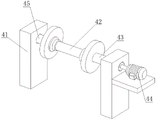
fig. 2 is a three-dimensional structure diagram of the tension roller assembly of the present invention;
FIG. 3 is a perspective view of the cutting assembly of the present invention;
FIG. 4 is a three-dimensional structure view of the material receiving assembly of the present invention;
fig. 5 is a three-dimensional structure diagram of the material receiving roller of the present invention.
In the figure: 1. a warp knitting machine; 2. a tension roller assembly; 21. a first press roller part; 211. a limiting strip block; 212. a pressure roller; 22. a limiting groove; 23. a first automatic telescopic rod; 24. a second press roll assembly; 25. a second automatic telescopic rod; 3. a cutting assembly; 31. a turntable; 32. fixing the bar block; 33. connecting blocks; 34. a blade head; 35. a tool apron plate; 36. a supporting block; 37. a concave sliding plate; 38. a first link; 39. a fixing plate; 391. a first motor; 4. a material receiving assembly; 41. supporting a fixed block; 42. a material receiving roller; 421. a second connecting cavity rod; 422. a limiting chuck component; 43. a third connecting column; 44. a second motor; 45. a fourth connecting column; 5. a work bench.
Detailed Description
The technical solutions in the embodiments of the present invention will be described clearly and completely with reference to the drawings in the embodiments of the present invention, and it is obvious that the described embodiments are only some embodiments of the present invention, not all embodiments. Based on the embodiments in the present invention, all other embodiments obtained by a person skilled in the art without creative work belong to the protection scope of the present invention.
For a further understanding of the present invention, reference will be made to the following detailed description taken in conjunction with the accompanying drawings.
With reference to fig. 1 and 2, a silk thread weaving device with a tensioning structure for manufacturing sparrow feather threads comprises a workbench 5, a warp knitting machine 1 arranged on the top surface of the workbench 5, a tensioning roller assembly 2, a cutting assembly 3 and a material receiving assembly 4, wherein the tensioning roller assembly 2 and the cutting assembly 3 are arranged between the warp knitting machine 1 and the material receiving assembly 4, the tensioning roller assembly 2 comprises a second automatic telescopic rod 25 arranged on the inner wall of the bottom of the tensioning roller assembly 2 and a first automatic telescopic rod 23 arranged on the inner wall of the top of the tensioning roller assembly 2, limiting grooves 22 are formed in two sides of the tensioning roller assembly 2, a first pressing roller component 21 is arranged at the upper end of the second automatic telescopic rod 25, and a second pressing roller assembly 24 is arranged at the lower end of the first automatic telescopic rod 23.
The present invention will be further described with reference to the following examples.
Example 1
Referring to fig. 1-5, the first pressing roller component 21 includes a pressing roller 212 connected to the output end of the second automatic telescopic rod 25 and a limiting bar 211 fixedly connected to both sides of the pressing roller 212, and the limiting bar 211 is slidably connected to the limiting groove 22, one end of the first automatic telescopic rod 23 is provided with a second pressing roller assembly 24, the second pressing roller assembly 24 is connected to the output end of the first automatic telescopic rod 23, and the second pressing roller assembly 24 and the first pressing roller component 21 are members made of the same component, the cutting assembly 3 includes a supporting block 36 disposed on one side of the tensioning roller assembly 2 and a tool apron plate 35 disposed on the top surface of the supporting block 36, one side of the supporting block 36 is provided with a fixing plate 39, the material receiving roller 42 includes a second connecting cavity rod 421 disposed in the middle of the material receiving roller 42, and both sides of the second connecting cavity rod 421 are connected to a limiting chuck component 422.
Example 2
Referring to fig. 1 and 3-5, the cutting assembly 3 includes a supporting block 36 disposed on one side of the tension roller assembly 2 and a tool apron plate 35 disposed on a top surface of the supporting block 36, a fixing plate 39 is disposed on one side of the supporting block 36, a first motor 391 is disposed on one side above the fixing plate 39, a rotary disc 31 is disposed on the other side above the fixing plate 39, the rotary disc 31 is connected to an output end of the first motor 391, a fixing bar 32 is fixedly connected to one side of the fixing plate 39, and two groups of fixing bar 32 are disposed, a first connecting rod 38 is fixedly connected to a top surface of the rotary disc 31, a concave sliding plate 37 is slidably connected to one side of the two groups of fixing bar 32, a concave sliding plate 37 is fixedly connected to one end of the first connecting rod 38, a connecting block 33 is further disposed on a top surface of the concave sliding plate 37, a blade head 34 is disposed at a bottom of the connecting block 33 and is matched with the tool apron plate 35, the material receiving assembly 4 includes a supporting and fixing block 41 disposed on one side of the cutting assembly 3, and the supporting and fixing blocks 41 are provided with two groups, one group of supporting and fixing blocks 41 is provided with a third connecting column 43 on one side, a second motor 44 is arranged on one side of the supporting and fixing block 41, the third connecting column 43 is connected with the output end of the second motor 44, the other group of supporting and fixing blocks 41 is provided with a fourth connecting column 45 on one side, a material receiving roller 42 is arranged between the third connecting column 43 and the fourth connecting column 45, one side of the material receiving roller 42 is fixedly connected with the third connecting column 43, the other side of the material receiving roller 42 is movably connected with the fourth connecting column 45, the material receiving roller 42 comprises a second connecting cavity rod 421 arranged in the middle of the material receiving roller 42, and both sides of the second connecting cavity rod 421 are clamped and connected with a limiting chuck component 422.
In summary, the following steps: the utility model discloses a sparrow feather thread manufacturing is with silk thread weaving device that has tensioning structure, the user draws out the sparrow feather pattern of weaving shaping in the tricot machine 1, pass its one side between tensioning roller subassembly 2 and cutting assembly 3, and fix on second connecting cavity pole 421, the sparrow feather pattern of weaving shaping this moment is in the position between first compression roller part 21 and the second compression roller subassembly 24 of tensioning roller subassembly 2, and place on the top surface of knife holder board 35, lie in between blade head 34 and knife holder board 35, the user can carry out tensioning adjustment to the sparrow feather pattern of making shaping through tensioning roller subassembly 2 at first, through opening first automatic telescopic link 23 and second automatic telescopic link 25, first automatic telescopic link 23 carries out concertina movement with second automatic telescopic link 25, drive second compression roller subassembly 24 and first compression roller part 21 and do the elevating movement, wherein spacing strip piece 211 plays the limiting effect to second compression roller subassembly 24 and first compression roller part 21, the tightness of the patterns is controlled by the vertical distance between the second press roll component 24 and the first press roll component 21, a user can adjust the proper position of the first press roll component 21 and the second press roll component 24, the first automatic telescopic rod 23 and the second automatic telescopic rod 25 are closed, the patterns are tensioned and limited by the first press roll component 21 and the second press roll component 24, the arrangement is convenient for the user to tension and adjust the patterns through the tensioning roll component 2 when weaving and receiving materials, thereby controlling the looseness of the patterns at the cutting component 3 and the receiving component 4, avoiding the phenomenon that the patterns excessively loosen or excessively compress the woven and formed sparrow feather lines to influence the overall effect of subsequent weaving and collection, and after the patterns are tensioned and adjusted by the tensioning roll component 2, the second motor 44 is started, drives the third connecting column 43 and the receiving roll 42 to rotate by the second motor 44, so that the second connecting cavity rod 421 automatically winds and collects the woven and formed patterns, when the woven patterns need to be cut off, the first motor 391 is started, the first motor 391 drives the rotary disc 31 to rotate, the rotary disc 31 drives the concave sliding plate 37 to move through the first connecting rod 38, the concave sliding plate 37 makes reciprocating linear motion along the fixed blocks 32 due to the limitation of the concave sliding plate 37 by the two groups of fixed blocks 32, the concave sliding plate 37 can drive the connecting block 33 and the blade head 34 to make reciprocating linear motion at the upper end of the knife holder plate 35, the cutting assembly 3 can cut the woven patterns, a subsequent user can separate the fourth connecting column 45 and the material receiving roller 42 by disassembling, then the limiting chuck component 422 and the second connecting cavity rod 421 are pulled open, the woven finished products automatically collected at the periphery of the second connecting cavity rod 421 are taken out, the arrangement avoids manual collection of the woven finished products, and can automatically collect the woven finished products, but also can automatically cut the cutting tool according to the needs of a user, the process is time-saving and labor-saving, the operation is convenient, and the practicability of the device is improved.
It is noted that, herein, relational terms such as first and second, and the like may be used solely to distinguish one entity or action from another entity or action without necessarily requiring or implying any actual such relationship or order between such entities or actions. Also, the terms "comprises," "comprising," or any other variation thereof, are intended to cover a non-exclusive inclusion, such that a process, method, article, or apparatus that comprises a list of elements does not include only those elements but may include other elements not expressly listed or inherent to such process, method, article, or apparatus.
Although embodiments of the present invention have been shown and described, it will be appreciated by those skilled in the art that changes, modifications, substitutions and alterations can be made in these embodiments without departing from the principles and spirit of the invention, the scope of which is defined in the appended claims and their equivalents.
Claims (8)
1. The utility model provides a sparrow feather preparation is with silk thread weaving device that has tensioning texture, includes workstation (5) and sets up tricot machine (1), tensioning roller subassembly (2), cutting component (3) and receipts material subassembly (4) at workstation (5) top surface, and tensioning roller subassembly (2) and cutting component (3) set up at tricot machine (1) and receive between material subassembly (4), its characterized in that: the tensioning roller assembly (2) comprises a second automatic telescopic rod (25) arranged on the inner wall of the bottom of the tensioning roller assembly (2) and a first automatic telescopic rod (23) arranged on the inner wall of the top of the tensioning roller assembly (2), limiting grooves (22) are formed in two sides of the tensioning roller assembly (2), a first pressure roller component (21) is arranged at the upper end of the second automatic telescopic rod (25), and a second pressure roller component (24) is arranged at the lower end of the first automatic telescopic rod (23).
2. The device for weaving sparrow feather yarns with yarns having a tension structure as claimed in claim 1, wherein: the first pressing roller component (21) comprises a pressing roller wheel (212) connected with the output end of the second automatic telescopic rod (25) and limiting bar blocks (211) fixedly connected to two sides of the pressing roller wheel (212), and the limiting bar blocks (211) are connected with the limiting grooves (22) in a sliding mode.
3. The device for weaving strings with a tension structure for manufacturing sparrow feather strings as claimed in claim 2, wherein: one end of the first automatic telescopic rod (23) is provided with a second compression roller assembly (24), the second compression roller assembly (24) is connected with the output end of the first automatic telescopic rod (23), and the second compression roller assembly (24) and the first compression roller component (21) are members made of the same component.
4. The device for weaving strings with a tension structure for manufacturing sparrow feather strings as claimed in claim 1, wherein: the cutting assembly (3) comprises a supporting block (36) arranged on one side of the tension roller assembly (2) and a cutter head plate (35) arranged on the top surface of the supporting block (36), and a fixing plate (39) is arranged on one side of the supporting block (36).
5. The device for weaving strings with a tension structure for manufacturing sparrow feather strings as claimed in claim 4, wherein: one side above the fixed plate (39) is provided with a first motor (391), the other side above the fixed plate (39) is provided with a turntable (31), the turntable (31) is connected with the output end of the first motor (391), one side of the fixed plate (39) is fixedly connected with a fixed strip block (32), and the fixed strip block (32) is provided with two groups.
6. The device for weaving strings with a tension structure for manufacturing sparrow feather strings as claimed in claim 5, wherein: the top surface of the rotary disc (31) is fixedly connected with a first connecting rod (38), one side of each of the two groups of fixed bar blocks (32) is slidably connected with a concave sliding plate (37), one end of the first connecting rod (38) is fixedly connected with the concave sliding plate (37), the top surface of the concave sliding plate (37) is also provided with a connecting block (33), the bottom of the connecting block (33) is provided with a blade head (34), and the blade head (34) is matched with the blade holder plate (35).
7. The device for weaving strings with a tension structure for manufacturing sparrow feather strings as claimed in claim 1, wherein: receive material subassembly (4) including setting up support fixed block (41) in cutting assembly (3) one side, and support fixed block (41) and be provided with two sets ofly, one of them group supports fixed block (41) one side and is provided with third spliced pole (43), and supports fixed block (41) one side and be provided with second motor (44), and third spliced pole (43) are connected with second motor (44) output, and another group supports fixed block (41) one side and is provided with fourth spliced pole (45).
8. The device for weaving sparrow feather yarns with yarns having a tension structure as claimed in claim 7, wherein: be provided with between third spliced pole (43) and fourth spliced pole (45) and receive material roller (42), receive material roller (42) one side and third spliced pole (43) fixed connection, receive material roller (42) opposite side and fourth spliced pole (45) swing joint, receive material roller (42) including setting up second connection chamber pole (421) at receipts material roller (42) middle part, the equal block in second connection chamber pole (421) both sides is connected with spacing chuck part (422).
Priority Applications (1)
| Application Number | Priority Date | Filing Date | Title |
|---|---|---|---|
| CN202221094247.0U CN217324524U (en) | 2022-05-09 | 2022-05-09 | Silk thread weaving device with tensioning structure for manufacturing sparrow feather thread |
Applications Claiming Priority (1)
| Application Number | Priority Date | Filing Date | Title |
|---|---|---|---|
| CN202221094247.0U CN217324524U (en) | 2022-05-09 | 2022-05-09 | Silk thread weaving device with tensioning structure for manufacturing sparrow feather thread |
Publications (1)
| Publication Number | Publication Date |
|---|---|
| CN217324524U true CN217324524U (en) | 2022-08-30 |
Family
ID=82951034
Family Applications (1)
| Application Number | Title | Priority Date | Filing Date |
|---|---|---|---|
| CN202221094247.0U Active CN217324524U (en) | 2022-05-09 | 2022-05-09 | Silk thread weaving device with tensioning structure for manufacturing sparrow feather thread |
Country Status (1)
| Country | Link |
|---|---|
| CN (1) | CN217324524U (en) |
-
2022
- 2022-05-09 CN CN202221094247.0U patent/CN217324524U/en active Active
Similar Documents
| Publication | Publication Date | Title |
|---|---|---|
| CN209260418U (en) | A kind of novel textile fabric cutting means | |
| CN217324524U (en) | Silk thread weaving device with tensioning structure for manufacturing sparrow feather thread | |
| CN212152910U (en) | Cutting device for weaving chemical fiber fabric | |
| CN116876189A (en) | Textile fabric cutting device for textile production | |
| CN108625143A (en) | A kind of intelligence manufacture Weaving device | |
| CN216274927U (en) | Cloth cutting device for garment processing | |
| CN211285007U (en) | Cutting device for producing polyester sewing thread | |
| CN210314904U (en) | Garment fabric edge finishing equipment | |
| CN112897143B (en) | Non-woven fabric production cutting and winding processing system | |
| CN209761943U (en) | Semi-automatic kludge of comb | |
| CN220789218U (en) | Cutting device for curtain cloth processing | |
| CN220264545U (en) | Knitting needle spreading machine | |
| CN219731428U (en) | Cotton cloth production cutting equipment | |
| CN211254743U (en) | Heat preservation and insulation chemical fiber production device convenient to collect product | |
| CN219384187U (en) | Full-automatic tape winder | |
| CN217869685U (en) | Cracker finisher is used in crepe facing material production | |
| CN220392866U (en) | Conductive cloth mounting module equipment for mounting camera | |
| CN220788987U (en) | Adjustable warp knitting machine | |
| CN220503356U (en) | Loom with tailor function | |
| CN214214078U (en) | Equipment is tailor to environmental air monitoring sampling filter membrane | |
| CN209052901U (en) | A kind of Apparatus for skin peeling for the production of nonwoven sofa cloth | |
| CN220007934U (en) | Cutting and finishing device for pulp paper production | |
| CN220840491U (en) | Paper yarn production facility | |
| CN218384610U (en) | Strip wire and cable weaving and forming device | |
| CN218836489U (en) | Carpet cutting machine |
Legal Events
| Date | Code | Title | Description |
|---|---|---|---|
| GR01 | Patent grant | ||
| GR01 | Patent grant |