CN217308015U - Explosion-proof emergency control case - Google Patents
Explosion-proof emergency control case Download PDFInfo
- Publication number
- CN217308015U CN217308015U CN202123141791.4U CN202123141791U CN217308015U CN 217308015 U CN217308015 U CN 217308015U CN 202123141791 U CN202123141791 U CN 202123141791U CN 217308015 U CN217308015 U CN 217308015U
- Authority
- CN
- China
- Prior art keywords
- explosion
- box body
- proof
- window
- button
- Prior art date
- Legal status (The legal status is an assumption and is not a legal conclusion. Google has not performed a legal analysis and makes no representation as to the accuracy of the status listed.)
- Active
Links
Images


Classifications
-
- Y—GENERAL TAGGING OF NEW TECHNOLOGICAL DEVELOPMENTS; GENERAL TAGGING OF CROSS-SECTIONAL TECHNOLOGIES SPANNING OVER SEVERAL SECTIONS OF THE IPC; TECHNICAL SUBJECTS COVERED BY FORMER USPC CROSS-REFERENCE ART COLLECTIONS [XRACs] AND DIGESTS
- Y02—TECHNOLOGIES OR APPLICATIONS FOR MITIGATION OR ADAPTATION AGAINST CLIMATE CHANGE
- Y02E—REDUCTION OF GREENHOUSE GAS [GHG] EMISSIONS, RELATED TO ENERGY GENERATION, TRANSMISSION OR DISTRIBUTION
- Y02E60/00—Enabling technologies; Technologies with a potential or indirect contribution to GHG emissions mitigation
- Y02E60/10—Energy storage using batteries
Abstract
The utility model discloses an explosion-proof emergency control case, include: the box body is provided with a notch, and the notch is arranged on one side surface of the box body; the window is arranged in the notch; the bracket is arranged in the box body and is arranged on the inner surface of the box body; one side of the box body is connected with an explosion-proof button, and at least one part of the explosion-proof button is arranged on the outer side of the box body; the normally open button is arranged in the box body, is arranged on the bracket and is arranged at one end of the explosion-proof button, and the explosion-proof button can be operated to open the normally open button; the indicating lamp is arranged in the box body, is arranged on the bracket and is arranged on one side of the window; a battery; a controller; a wiring board; the cable is prevented pressing from both sides and is tightly sealed the joint, and the lower extreme of box is connected a plurality of cables and is prevented pressing from both sides closely sealed the joint. The utility model discloses can satisfy the demand of nuclear power place to split type emergency light, satisfy explosion-proof demand, can externally see inside condition through explosion-proof button control internal state, accessible window.
Description
Technical Field
The utility model relates to an explosion-proof emergency control case's technical field especially relates to an explosion-proof emergency control case.
Background
Nowadays, most emergency lamps are directly connected to a circuit without corresponding protection measures, so that the emergency lamps do not have the condition of working under special conditions. At present, many explosion-proof indicator lamps are high in production cost; meanwhile, once the explosion-proof indicator lamp fails, the explosion-proof indicator lamp needs to be integrally replaced, and troubles are brought to subsequent maintenance.
SUMMERY OF THE UTILITY MODEL
In view of this, the utility model aims at providing an explosion-proof emergency control case.
In order to realize the purpose, the utility model discloses the technical scheme who takes does:
an explosion-proof emergency control box, wherein includes:
the box body is provided with a notch, and the notch is formed in one side face of the box body;
a window mounted within the slot;
the bracket is arranged inside the box body and is arranged on the inner surface of the box body;
the explosion-proof button is connected to one side of the box body, and at least one part of the explosion-proof button is arranged on the outer side of the box body;
the normally open button is arranged in the box body, is arranged on the bracket and is arranged at one end of the explosion-proof button, and the explosion-proof button can be operated to open the normally open button;
the indicating lamp is arranged in the box body, is arranged on the bracket and is arranged on one side of the window;
a battery mounted on the bracket;
a controller also mounted on the bracket, the controller being mounted below the battery;
a terminal block mounted on the controller;
the cable is prevented pressing from both sides and is tightly sealed the joint, the lower extreme of box is connected a plurality of the cable is prevented pressing from both sides and is tightly sealed the joint.
Foretell explosion-proof emergency control case, wherein, the box includes: case body and case lid, the case lid passes through threaded connection on the case body, the case body becomes the lid form, the notch is seted up in on the case lid, explosion-proof button with the cable is prevented pressing from both sides closely and is sealed the joint and all locate on the case body.
In the above explosion-proof emergency control box, the box cover is further provided with a handle, and the handle is connected to the surface of the box cover opposite to the box body.
The explosion-proof emergency control box further comprises: the window is characterized by comprising a plurality of mounting feet, wherein one ends of the mounting feet are connected with the box body, the mounting feet are connected to the side face, opposite to the window, of the box body, and mounting holes are formed in the other ends of the mounting feet.
Foretell explosion-proof emergency control case, wherein, the pilot lamp distance there is the first distance box bottom surface, the lower extreme of window is apart from there is the second distance the bottom of box, the upper end of window is apart from there is the third distance the bottom of box, the first distance is greater than the second distance, the first distance is less than the third distance.
The explosion-proof emergency control box is characterized in that the window is made of transparent glass.
Foretell explosion-proof emergency control case, wherein, the battery passes through the cable is prevented pressing from both sides closely and is sealed joint and outside emergent marker light electric connection.
The above-mentioned explosion-proof emergency control box, wherein, the pilot lamp, normally open button, the controller with the wiring board all with battery electric connection.
The utility model discloses owing to adopted above-mentioned technique, make it compare the positive effect that has with prior art and be:
(1) the utility model discloses can satisfy the demand of nuclear power place to split type emergency light.
(2) The utility model discloses satisfy explosion-proof demand, can externally see inside condition through explosion-proof button control, the accessible window.
Drawings
Fig. 1 is a schematic diagram of the explosion-proof emergency control box of the present invention.
Fig. 2 is a schematic diagram of the side sectional view of the explosion-proof emergency control box of the present invention.
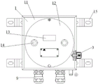
Fig. 3 is a schematic diagram of the internal components of the explosion-proof emergency control box of the present invention.
In the drawings: 1. a box body; 11. a box body; 12. a box cover; 13. a window; 14. a handle; 15. mounting bottom feet; 2. a support; 3. an explosion-proof button; 4. a normally open button; 5. an indicator light; 6. a battery; 7. a controller; 8. a wiring board; 9. the cable is prevented from clamping and is tightly sealed.
Detailed Description
The present invention will be further described with reference to the accompanying drawings and specific embodiments, but not limiting the present invention, and fig. 1 is a schematic diagram of an explosion-proof emergency control box of the present invention; fig. 2 is a schematic side sectional view of the explosion-proof emergency control box of the present invention; fig. 3 is a schematic diagram of the internal components of the explosion-proof emergency control box of the present invention, which is shown in fig. 1 to 3, and shows an explosion-proof emergency control box of a preferred embodiment, including:
the box body 1 is provided with a notch, and the notch is arranged on one side surface of the box body 1;
a window 13, wherein the window 13 is arranged in the groove;
the bracket 2 is arranged in the box body 1, and the bracket 2 is arranged on the inner surface of the box body 1;
the explosion-proof button 3 is connected with one side of the box body 1, and at least one part of the explosion-proof button 3 is arranged on the outer side of the box body 1;
the explosion-proof button 3 is arranged at one end of the explosion-proof button 4, and the explosion-proof button 3 can be operated to open the normally open button 4;
the indicating lamp 5 is arranged in the box body 1, the indicating lamp 5 is arranged on the bracket 2, and the indicating lamp 5 is arranged on one side of the window 13;
the battery 6, the battery 6 is installed on support 2;
the controller 7, the controller 7 is also installed on the support 2, the controller 7 is installed below the battery 6;
a terminal block 8, the terminal block 8 being mounted on the controller 7;
the tight sealing joint 9 is prevented pressing from both sides by the cable, and the tight sealing joint 9 is prevented pressing from both sides by a plurality of cables is connected to the lower extreme of box 1.
Here, in order to satisfy the explosion-proof requirement, the indicator lamp 5 cannot be directly mounted outside the case 1, and therefore observation is performed through the window 13.
In a preferred embodiment, the case 1 comprises: case body 11 and case lid 12, case lid 12 pass through threaded connection on case body 11, and case body 11 becomes the lid form, and the notch is seted up on case lid 12, and explosion-proof button 3 prevents pressing from both sides closely to seal and connect 9 and all locate on case body 11 with the cable.
In a preferred embodiment, the lid 12 is further provided with a handle 14, and the handle 14 is attached to a surface of the lid 12 opposite the body 11.
In a preferred embodiment, the method further comprises: installation footing 15, the one end of a plurality of installation footing 15 is connected with box 1, and a plurality of installation footing 15 are all connected on box 1 side relative with window 13, and the mounting hole has all been seted up to the other end of a plurality of installation footing 15.
The above is merely an example of the preferred embodiments of the present invention, and the embodiments and the protection scope of the present invention are not limited thereby.
The utility model discloses still have following embodiment on above-mentioned basis:
the utility model discloses a further embodiment, pilot lamp 5 has first distance apart from box 1 bottom surface, and the lower extreme of window 13 has the second distance apart from box 1's bottom, and there is the third distance window 13's upper end apart from box 1's bottom, and first distance is greater than the second distance, and first distance is less than the third distance.
As shown in fig. 2, the indicator lamp 5 is positioned between the upper and lower ends of the window 13, and the indicator lamp 5 can be externally observed through the window 13.
In a further embodiment of the present invention, the window 13 is made of transparent glass.
The utility model discloses a in the further embodiment, battery 6 passes through the cable and prevents pressing from both sides tight sealing joint 9 and outside emergent marker light electric connection.
In a further embodiment of the utility model, the pilot lamp 5, the normally open button 4, the controller 7 and the wiring board 8 all with battery 6 electric connection.
The above is only a preferred embodiment of the present invention, and not intended to limit the scope of the invention, and it should be appreciated by those skilled in the art that various equivalent substitutions and obvious changes made in the specification and drawings should be included within the scope of the present invention.
Claims (8)
1. An explosion-proof emergency control case, its characterized in that includes:
the box body is provided with a notch, and the notch is formed in one side face of the box body;
a window mounted within the slot;
the bracket is arranged inside the box body and is arranged on the inner surface of the box body;
the explosion-proof button is connected to one side of the box body, and at least one part of the explosion-proof button is arranged on the outer side of the box body;
the normally open button is arranged in the box body, is arranged on the bracket and is arranged at one end of the explosion-proof button, and the explosion-proof button can be operated to open the normally open button;
the indicating lamp is arranged in the box body, is arranged on the bracket and is arranged on one side of the window;
a battery mounted on the bracket;
a controller also mounted on the bracket, the controller being mounted below the battery;
a terminal block mounted on the controller;
the cable is prevented pressing from both sides and is tightly sealed the joint, the lower extreme of box is connected a plurality of the cable is prevented pressing from both sides and is tightly sealed the joint.
2. The explosion-proof emergency control box of claim 1, wherein the box body comprises: case body and case lid, the case lid passes through threaded connection on the case body, the case body becomes the lid form, the notch is seted up in on the case lid, explosion-proof button with the cable is prevented pressing from both sides closely and is sealed the joint and all locate on the case body.
3. The explosion proof emergency control case of claim 2 wherein said cover further comprises a handle attached to a surface of said cover opposite said case body.
4. The explosion-proof emergency control box of claim 1, further comprising: the window is characterized by comprising a plurality of mounting feet, wherein one ends of the mounting feet are connected with the box body, the mounting feet are connected to the side face, opposite to the window, of the box body, and mounting holes are formed in the other ends of the mounting feet.
5. The explosion-proof emergency control box of claim 1, wherein the indicator light is a first distance from the bottom surface of the box body, the lower end of the window is a second distance from the bottom of the box body, the upper end of the window is a third distance from the bottom of the box body, the first distance is greater than the second distance, and the first distance is less than the third distance.
6. The explosion-proof emergency control box of claim 1, wherein the window is made of transparent glass.
7. The explosion-proof emergency control box of claim 1, wherein said battery is electrically connected to an external emergency marker light through said cable anti-pinch tight seal.
8. The explosion proof emergency control box of claim 1, wherein said indicator light, said normally open button, said controller and said terminal block are all electrically connected to said battery.
Priority Applications (1)
| Application Number | Priority Date | Filing Date | Title |
|---|---|---|---|
| CN202123141791.4U CN217308015U (en) | 2021-12-14 | 2021-12-14 | Explosion-proof emergency control case |
Applications Claiming Priority (1)
| Application Number | Priority Date | Filing Date | Title |
|---|---|---|---|
| CN202123141791.4U CN217308015U (en) | 2021-12-14 | 2021-12-14 | Explosion-proof emergency control case |
Publications (1)
| Publication Number | Publication Date |
|---|---|
| CN217308015U true CN217308015U (en) | 2022-08-26 |
Family
ID=82921283
Family Applications (1)
| Application Number | Title | Priority Date | Filing Date |
|---|---|---|---|
| CN202123141791.4U Active CN217308015U (en) | 2021-12-14 | 2021-12-14 | Explosion-proof emergency control case |
Country Status (1)
| Country | Link |
|---|---|
| CN (1) | CN217308015U (en) |
-
2021
- 2021-12-14 CN CN202123141791.4U patent/CN217308015U/en active Active
Similar Documents
| Publication | Publication Date | Title |
|---|---|---|
| TW201448345A (en) | Antenna module and electronic system | |
| CN217308015U (en) | Explosion-proof emergency control case | |
| CN212725705U (en) | Electric connector with sealing assembly | |
| CN202711993U (en) | Switch housing | |
| CN204164984U (en) | Lighting device | |
| CN204315425U (en) | A kind of dustproof and waterproof switch | |
| CN209982239U (en) | Junction box structure of explosion-proof motor | |
| CN214506460U (en) | Novel equipment junction box device | |
| CN208508152U (en) | A kind of mounting structure of tear-away socket on carrier | |
| CN111627863A (en) | Power device protective cover | |
| CN205319346U (en) | Pull box | |
| CN112086920A (en) | Intrinsic safety junction box and heading machine | |
| CN219959831U (en) | Mining explosion-proof control box | |
| CN210609941U (en) | Dustproof and waterproof's vehicle terminal | |
| CN215343625U (en) | Control cabinet for mine card engine | |
| CN218678457U (en) | Reactive compensation equipment for low-voltage distribution network | |
| CN217010347U (en) | Surge protector with LED status indicator lamp | |
| CN218896972U (en) | Explosion-proof power distribution box | |
| CN211182962U (en) | Flame-proof type distribution box | |
| CN110518477B (en) | Heat dissipation type block terminal | |
| CN218267505U (en) | Self-closing valve shell structure | |
| CN110231790B (en) | Explosion-proof loop controller | |
| CN220753834U (en) | Signal adapter and circuit breaker | |
| CN214848258U (en) | Measurement switch | |
| CN210430020U (en) | Monitoring bolt structure, storage battery and storage battery monitoring system |
Legal Events
| Date | Code | Title | Description |
|---|---|---|---|
| GR01 | Patent grant | ||
| GR01 | Patent grant |