CN217307707U - Communication module testing device - Google Patents
Communication module testing device Download PDFInfo
- Publication number
- CN217307707U CN217307707U CN202220586979.5U CN202220586979U CN217307707U CN 217307707 U CN217307707 U CN 217307707U CN 202220586979 U CN202220586979 U CN 202220586979U CN 217307707 U CN217307707 U CN 217307707U
- Authority
- CN
- China
- Prior art keywords
- plate
- detection
- mounting
- shell
- limiting
- Prior art date
- Legal status (The legal status is an assumption and is not a legal conclusion. Google has not performed a legal analysis and makes no representation as to the accuracy of the status listed.)
- Active
Links
Images


Abstract
The utility model discloses a communication module testing arrangement, include: a housing; the two first detection mechanisms are arranged on the shell; the two bearing mechanisms are arranged on the upper surface of the shell, each bearing mechanism is provided with a module to be detected, each first detection mechanism can operatively drive the probes to contact with the two second detection mechanisms from top to bottom, the two second detection mechanisms are arranged on the upper surface of the shell, and each second detection mechanism is movably provided with a plug part; each plug portion is operatively connected to the module under test. Through right the utility model discloses an it is right to use, provides a device for carrying out short-term test to communication module, accomplishes detection mechanism and communication module's the back of being connected, and whole testing process passes through industrial computer control, has simplified the detection flow, can take notes each item test data, and once can detect a plurality of modules that await measuring simultaneously, has improved detection efficiency.
Description
Technical Field
The utility model relates to a communication module detects technical field, especially relates to a communication module testing arrangement.
Background
With the continuous and deep development of the construction of each field of the power grid, the demand of power communication equipment is rapidly increased, the large-batch product test on the production line is more and more concerned, but at present, part of the product test on the production line is still in the stage of manual operation instrument test, and the mode brings a lot of uncertainty to the production management and the product quality. Specifically, the existing product inspection and test completely depends on manual work, and particularly, the problems of low production efficiency, complex procedures, high possibility of errors and the like are caused when the detection end of the detection device is connected with the detected end of the communication module.
SUMMERY OF THE UTILITY MODEL
In view of the above, in order to solve the above problem, an object of the present invention is to provide a communication module detecting device, including:
a housing;
the two first detection mechanisms are both arranged on the shell and can move along the vertical direction in an operable manner, and each first detection mechanism is provided with a plurality of probes;
the two bearing mechanisms are arranged on the upper surface of the shell, a module to be detected is arranged on each bearing mechanism, and each first detection mechanism can operatively drive the probes to be contacted with the module to be detected from top to bottom;
the two second detection mechanisms are arranged on the upper surface of the shell, and each second detection mechanism is movably provided with a plug part; each plug portion is operatively connected to the module under test.
In another preferred embodiment, each of the first detection mechanisms includes: the probe pressing plate comprises a driving rod, a limiting part, a probe pressing plate, a fixing part and two guide rods, wherein the driving rod is arranged along the vertical direction, the driving rod is arranged on the limiting part in a vertically sliding mode, the limiting part is arranged on the fixing part, the fixing part is arranged on the upper surface of a shell, the upper surface of the probe pressing plate is fixedly arranged at the lower end of the driving rod, the two guide rods are arranged along the vertical direction, the lower ends of the two guide rods are fixedly arranged on the upper surface of the shell, and the probe pressing plate is arranged on the two guide rods in a sliding mode.
In another preferred embodiment, the fixing member includes: the two first mounting plates are arranged in the vertical direction, the lower ends of the two first mounting plates are mounted on the upper surface of the shell and are arranged oppositely, the two sides of the second mounting plate are connected with the two first mounting plates respectively, the second mounting plate is arranged in the vertical direction, and the limiting part is mounted on the second mounting plate.
In another preferred embodiment, each of the support mechanisms includes a detection plate mounted on the upper surface of the housing, the detection plate being mounted below the probe press plate, the upper surface of the detection plate defining a recess in which the module to be tested is operatively positioned.
In another preferred embodiment, the probe platen includes: the upper surface of the pressing plate body is fixedly installed at the lower end of the driving rod, two limiting holes are formed in one end, close to the fixing piece, of the pressing plate body, the pressing plate body is installed on the two guide rods in a sliding mode through the two limiting holes, the probes are installed on the lower surface of the pressing plate body in the vertical direction, and each probe is in contact with a module to be tested in an operable mode.
In another preferred embodiment, each of the second detection mechanisms includes: the detection device comprises a detection plug, a sliding seat and a mounting seat, wherein one end of the detection plug is mounted on the sliding seat, the sliding seat is slidably mounted on the mounting seat, the mounting seat is mounted on one side of the bearing mechanism, and a plug part is formed at the other end of the detection plug.
In another preferred embodiment, the method further comprises: antenna and industrial computer, antenna mounting are in the upper surface of casing, and the industrial computer is installed in the casing, and the antenna passes through the circuit to be connected with the industrial computer, and first detection mechanism and second detection mechanism all connect the industrial computer.
In another preferred embodiment, the stopper includes: limiting plate, stop collar and coupling assembling, limiting plate fixed mounting is on the second mounting panel, and the stop collar is installed in the lower extreme of limiting plate, and the actuating lever passes the stop collar setting with sliding from top to bottom, and coupling assembling sets up in the upper end of limiting plate, the upper end swing joint of coupling assembling and actuating lever, and coupling assembling is used for driving the elevating movement of actuating lever.
In another preferred embodiment, the method further comprises: the handle comprises a handle and two connecting arms, wherein one ends of the two connecting arms are respectively connected with two ends of the handle, and the other ends of the two connecting arms are respectively connected with the two connecting components.
In another preferred embodiment, the connecting assembly comprises: the driving rod driving device comprises a first connecting plate, a second connecting plate and a third connecting plate, wherein one end of the first connecting plate is fixedly connected with a limiting plate, the other end of the first connecting plate is hinged to one end of the second connecting plate, the other end of the second connecting plate is fixedly connected with the other end of the connecting arm, one end of the third connecting plate is hinged to the other end of the second connecting plate, and the other end of the third connecting plate is hinged to the upper end of the driving rod.
The utility model discloses owing to adopted above-mentioned technical scheme, make it compare the positive effect that has with prior art to be: through right the utility model discloses an it is right to use, provides a device for carrying out short-term test to communication module, accomplishes detection mechanism and communication module's the back of being connected, and whole testing process passes through industrial computer control, has simplified the detection flow, can take notes each item test data, and once can detect a plurality of modules that await measuring simultaneously, has improved detection efficiency.
Drawings
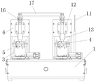
Fig. 1 is a front view of a communication module detecting device according to the present invention;
fig. 2 is a side view of a communication module detecting device according to the present invention;
fig. 3 is a top view of the communication module detecting device of the present invention.
In the drawings: 1. a housing; 2. a drive rod; 3. a guide bar; 4. a probe pressing plate; 5. a first mounting plate; 6. A second mounting plate; 7. detecting a plate; 8. detecting the plug; 9. a sliding seat; 10. a mounting base; 11. an antenna; 12. a limiting plate; 13. a limiting sleeve; 14. a first connecting plate; 15. a second connecting plate; 16. a third connecting plate; 17. a handle; 18. a connecting arm.
Detailed Description
The present invention will be further described with reference to the accompanying drawings and specific embodiments, which are not intended to limit the present invention.
As shown in fig. 1 to 3, a communication module detecting device according to a preferred embodiment includes:
a housing 1;
the two first detection mechanisms are both arranged on the shell 1 and can move along the vertical direction in an operable manner, and each first detection mechanism is provided with a plurality of probes;
the two bearing mechanisms are arranged on the upper surface of the shell 1, each bearing mechanism is provided with a module to be tested, and each first detection mechanism can operatively drive the probes to contact the module to be tested from top to bottom;
the two second detection mechanisms are arranged on the upper surface of the shell 1, and each second detection mechanism is movably provided with a plug part; each plug portion is operatively connected to the module under test.
In the actual use process, a module to be tested is placed on the bearing mechanism, the plug part of the second detection machine is moved, the plug part is inserted into the module to be tested for detection, the electric signal of the communication module is detected, after the detection is finished, the plug part is drawn out, then the first detection mechanism is moved downwards, a plurality of probes on the first detection mechanism are contacted with test points of the module to be tested, an SIM card is inserted into the module to be tested, the antenna 11 is connected, the power supply is turned on, the module to be tested is electrified, items to be tested are selected through the test software, the test is started by clicking, the test software automatically tests according to the selected test items in sequence, test results are automatically recorded, warning indication is carried out on unqualified test items, and the detection is finished.
Further, as a preferred embodiment, each of the first detecting mechanisms includes: the probe pressing plate comprises a driving rod 2, a limiting part, a probe pressing plate 4, a fixing part and two guide rods 3, wherein the driving rod 2 is arranged along the vertical direction, the driving rod 2 is arranged on the limiting part in a vertically sliding mode, the limiting part is arranged on the fixing part, the fixing part is arranged on the upper surface of a shell 1, the upper surface of the probe pressing plate 4 is fixedly arranged at the lower end of the driving rod 2, the two guide rods 3 are arranged along the vertical direction, the lower ends of the two guide rods 3 are fixedly arranged on the upper surface of the shell 1, and the probe pressing plate 4 is arranged on the two guide rods 3 in a sliding mode.
Further, as a preferred embodiment, the fixing member includes: two first mounting panels 5 and second mounting panel 6, two first mounting panels 5 set up along vertical direction, and the lower extreme of two first mounting panels 5 is installed in the upper surface of casing 1, and two first mounting panels 5 are just right to setting up mutually, and the both sides of second mounting panel 6 are connected with two first mounting panels 5 respectively, and second mounting panel 6 sets up along vertical direction, and the locating part is installed on second mounting panel 6.
Further, as a preferred embodiment, two bar holes have been seted up on the second mounting panel 6, and two bar holes all set up along vertical direction, and the locating part passes through two bar holes and installs on second mounting panel 6.
Further, as a preferred embodiment, each carrying mechanism includes a detection plate 7, the detection plate 7 is mounted on the upper surface of the housing 1, the detection plate 7 is mounted below the probe pressing plate 4, a groove is formed in the upper surface of the detection plate 7, and the module to be tested is operatively placed in the groove.
Further, as a preferred embodiment, the probe pressing plate 4 includes: the upper surface of the pressing plate body is fixedly installed at the lower end of the driving rod 2, two limit holes are formed in one end, close to the fixing piece, of the pressing plate body, the pressing plate body is installed on the two guide rods 3 in a sliding mode through the two limit holes, the probes are installed on the lower surface of the pressing plate body in the vertical direction, and each probe is in contact with a module to be tested in an operable mode.
Further, as a preferred embodiment, each of the second detecting mechanisms includes: the detection device comprises a detection plug 8, a sliding seat 9 and a mounting seat 10, wherein one end of the detection plug 8 is mounted on the sliding seat 9, the sliding seat 9 is slidably mounted on the mounting seat 10, the mounting seat 10 is mounted on one side of the bearing mechanism, and a plug part is formed at the other end of the detection plug 8.
Further, as a preferred embodiment, the method further comprises: antenna 11 and industrial computer, antenna 11 install in the upper surface of casing 1, and the industrial computer is installed in casing 1, and antenna 11 passes through the circuit and is connected with the industrial computer, and first detection mechanism and second detection mechanism all connect the industrial computer.
Further, as a preferred embodiment, the limiting member includes: limiting plate 12, stop collar 13 and coupling assembling, limiting plate 12 fixed mounting is on second mounting panel 6, and stop collar 13 is installed in the lower extreme of limiting plate 12, and actuating lever 2 passes stop collar 13 setting with sliding from top to bottom, and coupling assembling sets up in the upper end of limiting plate 12, coupling assembling and the upper end swing joint of actuating lever 2, and coupling assembling is used for driving the elevating movement of actuating lever 2.
Further, as an embodiment of a preferred, four bolt holes have been seted up on limiting plate 12, and every two bolt holes are seted up respectively in the relative position in limiting plate 12 and a bar hole, and limiting plate 12 passes through the bolt hole and installs on second mounting panel 6, and can adjust the height of limiting plate 12 according to actual conditions, carries out real-time adjustment.
Further, as a preferred embodiment, the method further comprises: the handle 17 and two linking arms 18, two linking arms 18's one end is connected with the both ends of handle 17 respectively, and two linking arms 18's the other end is connected with two coupling assembling respectively.
Further, as a preferred embodiment, the connecting assembly includes: first connecting plate 14, second connecting plate 15 and third connecting plate 16, the one end fixed connection limiting plate 12 of first connecting plate 14, the other end of first connecting plate 14 is articulated with the one end of second connecting plate 15, the other end of second connecting plate 15 and the other end fixed connection of connecting arm 18, the one end of third connecting plate 16 is articulated with the other end of second connecting plate 15, the other end of third connecting plate 16 is articulated with the upper end of actuating lever 2.
Further, as a preferred embodiment, pulling the handle 17, the handle 17 drives the two connecting arms 18 to rotate around the other end of the first connecting plate 14, and the second connecting plate 15 drives the third connecting plate 16 to rotate, and the third connecting plate 16 further drives the driving rod 2 to move upwards or downwards.
The above description is only an example of the preferred embodiments of the present invention, and the embodiments and the protection scope of the present invention are not limited thereby.
The utility model discloses still have following embodiment on above-mentioned basis:
the utility model discloses a in the further embodiment, through first detection mechanism, bear the combined action of mechanism, antenna 11 and industrial computer, to the test of functions such as the module that awaits measuring 4G, ethernet, LORA, battery voltage and consumption.
The utility model discloses a in the further embodiment, a photoelectric converter is still connected to second detection mechanism's sliding seat 9, and is qualified through the test result to the signal of telecommunication of module to be tested, judges whether the module to be tested is qualified.
The utility model discloses a in the further embodiment, be provided with an alarm lamp on the casing 1, when the abnormal conditions appearing, the alarm lamp begins to carry out the police dispatch newspaper.
The above description is only an example of the preferred embodiment of the present invention, and not intended to limit the scope of the present invention, and those skilled in the art should be able to realize the equivalent alternatives and obvious variations of the present invention.
Claims (10)
1. A communication module testing apparatus, comprising:
a housing;
the two first detection mechanisms are both arranged on the shell and can move along the vertical direction in an operable manner, and each first detection mechanism is provided with a plurality of probes;
the two bearing mechanisms are arranged on the upper surface of the shell, a module to be tested is arranged on each bearing mechanism, and each first detection mechanism can operatively drive the probes to contact with the module to be tested from top to bottom;
the two second detection mechanisms are arranged on the upper surface of the shell, and each second detection mechanism is movably provided with a plug part; each plug part is operatively connected to the module under test in a plug-in manner.
2. The communication module testing apparatus of claim 1, wherein each of the first detecting mechanisms comprises: the probe pressing plate comprises a driving rod, a limiting part, a probe pressing plate, a fixing part and two guide rods, wherein the driving rod is arranged along the vertical direction, the driving rod is arranged on the limiting part in a vertically sliding mode, the limiting part is arranged on the fixing part, the fixing part is arranged on the upper surface of the shell, the upper surface of the probe pressing plate is fixedly arranged at the lower end of the driving rod, two guide rods are arranged along the vertical direction, two lower ends of the guide rods are fixedly arranged on the upper surface of the shell, and the probe pressing plate is arranged on the guide rods in a sliding mode.
3. The communication module testing apparatus of claim 2, wherein the fixture comprises: the mounting structure comprises two first mounting plates and a second mounting plate, wherein the first mounting plates are arranged along the vertical direction, the lower ends of the first mounting plates are arranged on the upper surface of the shell, the first mounting plates are arranged oppositely, the two sides of the second mounting plate are connected with the two first mounting plates respectively, the second mounting plate is arranged along the vertical direction, and the limiting parts are arranged on the second mounting plate.
4. The telecommunications module testing apparatus of claim 2, wherein each of said support mechanisms includes a test plate, said test plate being mounted to an upper surface of said housing, said test plate being mounted below said probe platens, said test plate having a recess formed in an upper surface thereof, said module to be tested being operatively positioned in said recess.
5. The telecommunications module testing apparatus of claim 2, wherein the probe hold down comprises: the upper surface of the pressing plate body is fixedly installed at the lower end of the driving rod, two limiting holes are formed in one end, close to the fixing piece, of the pressing plate body, the pressing plate body is installed on the two guide rods in a sliding mode through the two limiting holes, the probes are installed on the lower surface of the pressing plate body in the vertical direction, and each probe is operationally contacted with the module to be tested.
6. The apparatus according to claim 1, wherein each of the second detecting mechanisms comprises: the detection device comprises a detection plug, a sliding seat and a mounting seat, wherein one end of the detection plug is mounted on the sliding seat, the sliding seat is slidably mounted on the mounting seat, the mounting seat is mounted on one side of the bearing mechanism, and the other end of the detection plug is provided with a plug part.
7. The communication module testing apparatus of claim 1, further comprising: the antenna is installed on the upper surface of the shell, the industrial personal computer is installed in the shell, the antenna is connected with the industrial personal computer through a circuit, and the first detection mechanism and the second detection mechanism are connected with the industrial personal computer.
8. The device as claimed in claim 3, wherein the stopper comprises: limiting plate, stop collar and coupling assembling, limiting plate fixed mounting in on the second mounting panel, the stop collar install in the lower extreme of limiting plate, the actuating lever passes with sliding from top to bottom the stop collar sets up, coupling assembling set up in the upper end of limiting plate, coupling assembling with the upper end swing joint of actuating lever, coupling assembling is used for driving the elevating movement of actuating lever.
9. The communication module testing apparatus of claim 8, further comprising: the handle comprises a handle and two connecting arms, wherein one ends of the two connecting arms are respectively connected with two ends of the handle, and the other ends of the two connecting arms are respectively connected with the two connecting components.
10. The telecommunications module testing apparatus of claim 9, wherein the connection assembly comprises: first connecting plate, second connecting plate and third connecting plate, the one end fixed connection of first connecting plate the limiting plate, the other end of first connecting plate with the one end of second connecting plate is articulated, the other end of second connecting plate with the other end fixed connection of linking arm, the one end of third connecting plate with the other end of second connecting plate is articulated, the other end of third connecting plate with the upper end of actuating lever is articulated.
Priority Applications (1)
| Application Number | Priority Date | Filing Date | Title |
|---|---|---|---|
| CN202220586979.5U CN217307707U (en) | 2022-03-17 | 2022-03-17 | Communication module testing device |
Applications Claiming Priority (1)
| Application Number | Priority Date | Filing Date | Title |
|---|---|---|---|
| CN202220586979.5U CN217307707U (en) | 2022-03-17 | 2022-03-17 | Communication module testing device |
Publications (1)
| Publication Number | Publication Date |
|---|---|
| CN217307707U true CN217307707U (en) | 2022-08-26 |
Family
ID=82935750
Family Applications (1)
| Application Number | Title | Priority Date | Filing Date |
|---|---|---|---|
| CN202220586979.5U Active CN217307707U (en) | 2022-03-17 | 2022-03-17 | Communication module testing device |
Country Status (1)
| Country | Link |
|---|---|
| CN (1) | CN217307707U (en) |
Cited By (1)
| Publication number | Priority date | Publication date | Assignee | Title |
|---|---|---|---|---|
| CN117640482A (en) * | 2024-01-26 | 2024-03-01 | 陕西恒光测控技术有限公司 | Communication module testing arrangement |
-
2022
- 2022-03-17 CN CN202220586979.5U patent/CN217307707U/en active Active
Cited By (2)
| Publication number | Priority date | Publication date | Assignee | Title |
|---|---|---|---|---|
| CN117640482A (en) * | 2024-01-26 | 2024-03-01 | 陕西恒光测控技术有限公司 | Communication module testing arrangement |
| CN117640482B (en) * | 2024-01-26 | 2024-04-05 | 陕西恒光测控技术有限公司 | Communication module testing arrangement |
Similar Documents
| Publication | Publication Date | Title |
|---|---|---|
| CN217307707U (en) | Communication module testing device | |
| CN209992617U (en) | Circuit board combined function testing device | |
| CN209992543U (en) | Circuit board testing jig | |
| CN207263864U (en) | A kind of switching detection device | |
| CN208704919U (en) | Temperature measurement card test fixture | |
| CN208420983U (en) | Device for testing circuit board function | |
| CN208270714U (en) | Test marking machine with barcode scanning device | |
| CN214954044U (en) | Electric energy meter detection device and detection equipment | |
| CN109490759A (en) | A kind of PCBA automatic detection tooling | |
| CN115236487A (en) | A plant needle tool for circuit board test | |
| CN209471190U (en) | BMS plate test fixture | |
| CN216718492U (en) | District intelligent terminal is with handing over to adopt board test needle bed | |
| CN218122023U (en) | A quick interfacing apparatus for charger detects | |
| CN220121175U (en) | Test fixture of hydrogen water machine control panel | |
| CN212083604U (en) | Circuit board test fixture | |
| CN218298443U (en) | Servo driver FCT test fixture | |
| CN219434911U (en) | Probe impedance test fixture | |
| CN111983439A (en) | Relay positioning testing device and relay testing equipment using same | |
| CN220491012U (en) | New energy vehicle-mounted power supply comprehensive testing machine | |
| CN209764937U (en) | lithium battery module open circuit voltage detection device | |
| CN217543322U (en) | Mainboard function test instrument | |
| CN220691066U (en) | Polarity and pressure difference testing tool for battery module | |
| CN214011363U (en) | Product resistance value test equipment | |
| CN219348932U (en) | Electrical measurement jig | |
| CN218995457U (en) | Test fixture for embedded butt joint interface board of prune pie |
Legal Events
| Date | Code | Title | Description |
|---|---|---|---|
| GR01 | Patent grant | ||
| GR01 | Patent grant |