CN217277312U - Building element loading test connection system - Google Patents
Building element loading test connection system Download PDFInfo
- Publication number
- CN217277312U CN217277312U CN202122997602.7U CN202122997602U CN217277312U CN 217277312 U CN217277312 U CN 217277312U CN 202122997602 U CN202122997602 U CN 202122997602U CN 217277312 U CN217277312 U CN 217277312U
- Authority
- CN
- China
- Prior art keywords
- support
- sample
- testing machine
- plate
- limiting
- Prior art date
- Legal status (The legal status is an assumption and is not a legal conclusion. Google has not performed a legal analysis and makes no representation as to the accuracy of the status listed.)
- Active
Links
Images


Abstract
The utility model relates to a building element load test connection system, including the testing machine, the outer end of the actuator of testing machine is equipped with the sample link and is connected with the sample, and the inboard of one side stand bottom of testing machine is equipped with the jack, and the inboard of opposite side stand bottom is equipped with the butt device, and rigid coupling support one and support two on the base of testing machine, the middle part of the stand of testing machine is equipped with holding frame centre gripping sample. The utility model discloses can effectively restrict the outer phenomenon of moving in the plane in the experiment, it is more accurate to reach the test result, more is close the actual purpose of engineering. The applicability is high, the actual test field assembly is convenient, and the energy is saved and the efficiency is high.
Description
Technical Field
The utility model relates to a structural test field, in particular to building element load test connection system.
Background
In recent years, with the rapid development of science and technology and economy in China, more and more college students walk into laboratories to carry out large-scale tests on soil and wood. At present, in order to seek development and progress in civil engineering specialties of various scientific research institutes and colleges in China, a plurality of large-scale testing machines with advanced technology are introduced. However, for some early test devices, the problem of out-of-plane displacement of the test piece is easy to occur in the loading process, the connection between the test piece and the test device is not in accordance with the actual boundary conditions of the project, and the purchase of new test devices is huge in cost.
The currently studied test equipment connection system has the following problems:
firstly, boundary conditions and interaction formed by a connecting system of test equipment do not accord with engineering practice.
And secondly, the test equipment connecting system cannot effectively limit out-of-plane displacement.
The test equipment connection system cannot achieve multiple applicability and is single in function, the connection device cannot be adjusted according to different sizes of test pieces, reworking is needed, and energy and materials are not saved.
Disclosure of Invention
The utility model aims to solve the technical problem that a building element load test connection system is provided, for the accuracy of test result provides the guarantee.
In order to achieve the above object, the utility model adopts the following technical scheme:
the utility model provides a building element loading test connection system, includes the testing machine, and the outer end of the actuator of testing machine is equipped with the sample link and is connected with the sample, and the inboard of one side stand bottom of testing machine is equipped with the jack, and the inboard of another side stand bottom is equipped with the top and connects the device, and rigid coupling support one and support two on the base of testing machine, the middle part of the stand of testing machine is equipped with the centre gripping frame centre gripping sample.
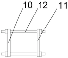
The sample connecting frame comprises a first pressing plate and a second pressing plate, and the first pressing plate and the second pressing plate clamp a sample and are connected through fastening bolts.
The jacking device comprises a limiting plate, and a round rod is transversely arranged in the middle of the limiting plate.
The first support comprises a first support base plate, support side plates are symmetrically arranged on two sides of the first support base plate, and limiting round holes are correspondingly formed in the two support side plates and used for penetrating and sleeving limiting rods.
The second support comprises a second support base plate, support vertical plates are symmetrically arranged on two sides of the second support base plate, and limiting long round holes are correspondingly formed in the two support vertical plates and used for penetrating and sleeving limiting rods.
The clamping frame comprises clamping plates which are symmetrically arranged, the two ends of each clamping plate are connected through long bolts, the parts of the clamping plates, corresponding to the samples, are connected with a supporting plate, and pulleys are arranged on the supporting plate and abutted to the samples.
Compared with the prior art, the beneficial effects of the utility model are that:
the utility model discloses can effectively restrict the outer phenomenon of moving in the plane in the experiment, it is more accurate to reach the test result, more is close the actual purpose of engineering. The applicability is high, and the actual test is assembled conveniently on site, and is energy-saving and efficient.
Drawings
Fig. 1 is a schematic structural diagram of the present invention.
FIG. 2 is a schematic view of a sample attachment stand.
Fig. 3 is a schematic view of the butting device.
FIG. 4 is a schematic view of a holder.
Fig. 5 is a schematic view of the second support.
FIG. 6 is a schematic view of a holder.
FIG. 7 is a top view of the holder.
In the figure: a testing machine 1; an actuator 2 of the testing machine; a sample connection rack 3; sample 4; a jack 5; a butting device 6; a first support saddle 7; a second support 8; a holding frame 9; a first pressing plate 10; a second pressing plate 11; a fastening bolt 12; a position limiting plate 13; a round bar 14; a first support base plate 15; a support side plate 16; a limit round hole 17 is arranged; a second support base plate 18; a support vertical plate 19; a limiting long round hole 20; clamp plate 21, long bolt 22, brace 23, pulley 24.
Detailed Description
The following further describes the embodiments of the present invention with reference to the attached drawings:
as shown in figures 1-7, a building element loading test connection system comprises a testing machine 1, a sample connection frame 3 is arranged at the outer end of an actuator 2 of the testing machine and connected with a sample 4, a jack 5 is arranged on the inner side of the bottom of a stand column on one side of the testing machine 1, a jacking device 6 is arranged on the inner side of the bottom of the stand column on the other side of the testing machine, a first support 7 and a second support 8 are fixedly connected to a base of the testing machine 1, and a clamping frame 9 is arranged in the middle of the stand column of the testing machine 1 and used for clamping the sample 4.
The sample connecting frame 3 comprises a first pressure plate 10 and a second pressure plate 11, and the first pressure plate 10 and the second pressure plate 11 clamp the sample 4 and are connected through a fastening bolt 12.
The abutting device 6 comprises a limiting plate 13, the limiting plate 13 is connected with the upright column through a bolt, and a round rod 14 is transversely arranged in the middle of the limiting plate 13.
The first support 7 comprises a first support base plate 15, support side plates 16 are symmetrically arranged on two sides of the first support base plate 15, and limiting round holes 17 are correspondingly formed in the two support side plates 16 and used for penetrating and sleeving limiting rods.
The second support 8 comprises a second support base plate 18, two support vertical plates 19 are symmetrically arranged on two sides of the second support base plate 18, and the two support vertical plates 19 are correspondingly provided with limiting long round holes 20 for penetrating and sleeving limiting rods.
The holding frame 9 comprises symmetrically arranged clamping plates 21, two ends of the two clamping plates 21 are respectively connected through long bolts 22, a part of the clamping plate 22 corresponding to the sample is connected with a supporting plate 23, and a pulley 24 is arranged on the supporting plate 23 and is abutted to the sample 4.
A limiting round hole is reserved in the sample 4 and corresponds to the first support 7 and the second support 8 respectively, a limiting rod penetrates through the limiting round hole 17 of the first support 7 and the limiting round hole of the sample 4 to form a fixed pivot, and a limiting long round hole 20 of the second support 8 and the limiting round hole of the sample penetrate through the limiting rod to form a hinge pivot. The jack 5 exerts a force on the side against the test specimen 4. The actuator 2 of the testing machine pushes the sample to carry out the low-cycle reciprocating loading test.
Above utility model, to the ordinary technical personnel in this technical field, can also be right without deviating from the principle of the utility model, these improve and decorate and also fall into the protection scope of the utility model claims. The above description is only the preferred embodiment of the present invention, but the scope of the present invention is not limited thereto, and any person skilled in the art can substitute or change the technical solution and the concept of the present invention within the technical scope disclosed in the present invention.
Claims (6)
1. The utility model provides a building element loading test connection system, its characterized in that, includes the testing machine, and the outer end of the actuator of testing machine is equipped with the sample link and is connected with the sample, and the inboard of one side stand bottom of testing machine is equipped with the jack, and the inboard of another side stand bottom is equipped with the top and connects the device, and rigid coupling support one and support two on the base of testing machine, the middle part of the stand of testing machine is equipped with the centre gripping frame centre gripping sample.
2. The building component loading test connection system of claim 1, wherein the sample connection frame comprises a first pressing plate and a second pressing plate, and the first pressing plate and the second pressing plate clamp the sample and are connected through fastening bolts.
3. The building element loading test connecting system according to claim 1, wherein the abutting device comprises a limiting plate, and a round rod is transversely arranged in the middle of the limiting plate.
4. The building element loading test connecting system according to claim 1, wherein the first support comprises a first support bottom plate, support side plates are symmetrically arranged on two sides of the first support bottom plate, and limiting round holes are correspondingly formed in the two support side plates and used for penetrating and sleeving limiting rods.
5. The building element loading test connecting system according to claim 1, wherein the second support comprises a second support base plate, vertical support plates are symmetrically arranged on two sides of the second support base plate, and limiting oblong holes are correspondingly formed in the two vertical support plates and used for allowing limiting rods to penetrate through.
6. The building component loading test connection system according to claim 1, wherein the holding frame comprises symmetrically arranged clamping plates, two ends of the two clamping plates are respectively connected through a long bolt, the parts of the clamping plates corresponding to the test sample are connected with the support plate, and the support plate is provided with pulleys to be abutted with the test sample.
Priority Applications (1)
| Application Number | Priority Date | Filing Date | Title |
|---|---|---|---|
| CN202122997602.7U CN217277312U (en) | 2021-12-01 | 2021-12-01 | Building element loading test connection system |
Applications Claiming Priority (1)
| Application Number | Priority Date | Filing Date | Title |
|---|---|---|---|
| CN202122997602.7U CN217277312U (en) | 2021-12-01 | 2021-12-01 | Building element loading test connection system |
Publications (1)
| Publication Number | Publication Date |
|---|---|
| CN217277312U true CN217277312U (en) | 2022-08-23 |
Family
ID=82881737
Family Applications (1)
| Application Number | Title | Priority Date | Filing Date |
|---|---|---|---|
| CN202122997602.7U Active CN217277312U (en) | 2021-12-01 | 2021-12-01 | Building element loading test connection system |
Country Status (1)
| Country | Link |
|---|---|
| CN (1) | CN217277312U (en) |
-
2021
- 2021-12-01 CN CN202122997602.7U patent/CN217277312U/en active Active
Similar Documents
| Publication | Publication Date | Title |
|---|---|---|
| CN206824813U (en) | A kind of non-drum type framed side wallboard agitating friction weldering clamping tooling of track traffic | |
| CN205949773U (en) | Forging fixture | |
| CN207882052U (en) | Multifunction structure frame | |
| CN217277312U (en) | Building element loading test connection system | |
| CN214309860U (en) | Hardness detection device for material science | |
| CN208443652U (en) | A kind of built-in hanger tensile strength tests device | |
| CN203337452U (en) | Pressured clamp of compression-testing machine | |
| CN210720117U (en) | Self-balancing reinforcing bar and concrete bonding testing arrangement that slides | |
| CN206824812U (en) | A kind of track traffic drum type framed side wallboard agitating friction weldering clamping tooling | |
| CN216695832U (en) | Clamping device for universal testing machine | |
| CN216144597U (en) | Microcomputer controlled constant stress pressure tester | |
| CN213544207U (en) | Impact collision test stand | |
| CN114813407A (en) | Bidirectional tensile fatigue test sample, test device and test method for T-shaped welded joint | |
| CN206132460U (en) | A device that bends for stainless steel intergranular corrosion test | |
| CN214173989U (en) | Clamping tool for testing compressive property of scaffold fastener | |
| CN214844449U (en) | Building insulation material tensile strength detection device | |
| CN211374352U (en) | Early compressive strength check out test set of high strength concrete | |
| CN210953454U (en) | Engineering quality supervises uses concrete sampling equipment | |
| CN214952670U (en) | Simple device for civil engineering structure detection | |
| CN208825930U (en) | A kind of automobile left front longitudinal beam fixture | |
| CN219444008U (en) | Special fixture for arm support part | |
| CN113155631A (en) | Simple device and method for providing concrete carrying | |
| CN218496623U (en) | Concrete analysis device | |
| CN213481893U (en) | Cement resistance to compression detects anchor clamps | |
| CN215148525U (en) | U type SCR diesel oil post processor assembly support assembly fixture |
Legal Events
| Date | Code | Title | Description |
|---|---|---|---|
| GR01 | Patent grant | ||
| GR01 | Patent grant |