CN217238736U - Safety protection device for computer power supply - Google Patents
Safety protection device for computer power supply Download PDFInfo
- Publication number
- CN217238736U CN217238736U CN202220227293.7U CN202220227293U CN217238736U CN 217238736 U CN217238736 U CN 217238736U CN 202220227293 U CN202220227293 U CN 202220227293U CN 217238736 U CN217238736 U CN 217238736U
- Authority
- CN
- China
- Prior art keywords
- wall
- fixedly arranged
- protective shell
- computer power
- power supply
- Prior art date
- Legal status (The legal status is an assumption and is not a legal conclusion. Google has not performed a legal analysis and makes no representation as to the accuracy of the status listed.)
- Expired - Fee Related
Links
- 239000000428 dust Substances 0.000 claims abstract description 67
- 230000001681 protective effect Effects 0.000 claims abstract description 51
- 230000017525 heat dissipation Effects 0.000 claims abstract description 39
- XLYOFNOQVPJJNP-UHFFFAOYSA-N water Substances O XLYOFNOQVPJJNP-UHFFFAOYSA-N 0.000 claims abstract description 38
- 238000001035 drying Methods 0.000 claims description 19
- 230000000903 blocking effect Effects 0.000 claims description 7
- 238000005086 pumping Methods 0.000 claims description 3
- 238000010521 absorption reaction Methods 0.000 description 10
- 238000000034 method Methods 0.000 description 9
- 239000000110 cooling liquid Substances 0.000 description 8
- 239000003651 drinking water Substances 0.000 description 5
- 235000020188 drinking water Nutrition 0.000 description 5
- 239000002826 coolant Substances 0.000 description 3
- 239000007788 liquid Substances 0.000 description 3
- 230000009286 beneficial effect Effects 0.000 description 2
- 238000004140 cleaning Methods 0.000 description 2
- 239000002274 desiccant Substances 0.000 description 2
- 238000010586 diagram Methods 0.000 description 2
- 238000009434 installation Methods 0.000 description 2
- OKTJSMMVPCPJKN-UHFFFAOYSA-N Carbon Chemical compound [C] OKTJSMMVPCPJKN-UHFFFAOYSA-N 0.000 description 1
- 238000007599 discharging Methods 0.000 description 1
- 230000000694 effects Effects 0.000 description 1
- 238000005516 engineering process Methods 0.000 description 1
- 229910002804 graphite Inorganic materials 0.000 description 1
- 239000010439 graphite Substances 0.000 description 1
- 239000000463 material Substances 0.000 description 1
- 230000000737 periodic effect Effects 0.000 description 1
Images

Classifications
-
- Y—GENERAL TAGGING OF NEW TECHNOLOGICAL DEVELOPMENTS; GENERAL TAGGING OF CROSS-SECTIONAL TECHNOLOGIES SPANNING OVER SEVERAL SECTIONS OF THE IPC; TECHNICAL SUBJECTS COVERED BY FORMER USPC CROSS-REFERENCE ART COLLECTIONS [XRACs] AND DIGESTS
- Y02—TECHNOLOGIES OR APPLICATIONS FOR MITIGATION OR ADAPTATION AGAINST CLIMATE CHANGE
- Y02D—CLIMATE CHANGE MITIGATION TECHNOLOGIES IN INFORMATION AND COMMUNICATION TECHNOLOGIES [ICT], I.E. INFORMATION AND COMMUNICATION TECHNOLOGIES AIMING AT THE REDUCTION OF THEIR OWN ENERGY USE
- Y02D10/00—Energy efficient computing, e.g. low power processors, power management or thermal management
Landscapes
- Cooling Or The Like Of Electrical Apparatus (AREA)
Abstract
The utility model provides a be used for computer power safety device. The safety protection device for the computer power supply comprises a protective shell; the placing plate is fixedly arranged on the inner wall of the protective shell; the computer power supply body is fixedly arranged on the top of the placing plate; the water storage tank is fixedly arranged on the inner wall of the bottom of the protective shell; the fan is fixedly arranged on the inner wall of one side of the protective shell; the water pump is fixedly arranged on the inner wall of the bottom of the protective shell; the heat dissipation coil is fixedly arranged at the bottom of the placing plate; and the radiating fins are fixedly arranged at the bottom of the radiating coil. The utility model provides a be used for computer power safety device has and can prevent that power temperature is too high, the advantage of the clearance of being convenient for of dust.
Description
Technical Field
The utility model relates to a computer technology field especially relates to a be used for computer power safety device.
Background
The computer belongs to weak current products, that is to say, the working voltage of the components is relatively low, generally within plus or minus 12 volts, and is direct current. And the common commercial power is 220V alternating current and can not be directly used on computer parts. Therefore, a computer, like many household appliances, needs a power supply part for converting common mains supply into a voltage usable by the computer, and is generally installed inside the computer.
However, in the use process of the existing computer power supply, a large amount of dust is often attached to a dust screen on the computer power supply, and when the dust is cleaned, a computer cover plate is basically opened firstly, then the computer cover plate is cleaned manually, and the computer cover plate is installed back after the cleaning is completed, so that the whole cleaning process is troublesome, and along with the increase of the use time of the computer power supply, the computer power supply is easily damaged due to the fact that the internal temperature cannot be quickly dissipated, and is very inconvenient to use.
Therefore, there is a need to provide a new safety protection device for computer power supply to solve the above-mentioned technical problems.
SUMMERY OF THE UTILITY MODEL
The utility model provides a technical problem provide a can prevent that power temperature is too high, the dust is convenient for clear up be used for computer power safety device.
In order to solve the technical problem, the utility model provides a be used for computer power safety device includes: a protective shell; the placing plate is fixedly arranged on the inner wall of the protective shell; the computer power supply body is fixedly arranged on the top of the placing plate; the water storage tank is fixedly arranged on the inner wall of the bottom of the protective shell; the fan is fixedly arranged on the inner wall of one side of the protective shell; the water pump is fixedly arranged on the inner wall of the bottom of the protective shell; the heat dissipation coil is fixedly arranged at the bottom of the placing plate; the heat dissipation fins are fixedly arranged at the bottom of the heat dissipation coil; the dust collection box is fixedly arranged on the outer wall of one side of the protective shell; the heat dissipation groove is formed in the top of the protective shell; the filter plate is fixedly arranged on the inner wall of the heat dissipation groove; the rectangular frame is fixedly arranged at the top of the protective shell; the motor is fixedly arranged on the outer wall of one side of the rectangular frame; the exhaust fan is fixedly arranged at the top of the dust collection box; a drying cabinet disposed within the protective housing.
Preferably, fixed mounting has the guard plate on the both sides inner wall of rectangle frame, set up the cavity in the guard plate, rotate on the rectangle frame and install the screw rod, just the one end of screw rod with the output shaft fixed connection of motor, just the screw rod is located in the cavity.
Preferably, the threaded rod is provided with a connecting block in a threaded manner, the bottom of the connecting block extends to the bottom of the protective plate, a scraper is fixedly arranged at the bottom of the connecting block, and the bottom of the scraper is movably connected with the top of the filter plate.
Preferably, fixed mounting has the drinking-water pipe on the water inlet of water pump, the one end of drinking-water pipe extends to in the storage water tank, just fixed mounting has the connecting pipe on the delivery port of water pump, the top of connecting pipe with heat dissipation coil pipe fixed connection.
Preferably, fixed mounting has the ash discharge pipe on the output tube of air exhauster, the bottom of ash discharge pipe with the top fixed connection of dust collection box, just fixed mounting has the dust absorption pipe on the output of air exhauster, one of dust absorption pipe serves fixed mounting has the dust absorption fill, the dust absorption fill with one side outer wall fixed connection of rectangle frame.
Preferably, an ash discharging groove is formed in the outer wall of one side of the dust collection box, an ash blocking plate is hinged to the outer wall of one side of the dust collection box, and the ash blocking plate is fixedly connected with the dust collection box through a first bolt.
Preferably, a sliding groove is formed in the outer wall of one side of the protective shell, the drying box is connected with the inner wall of the sliding groove in a sliding mode, a cover plate is arranged on the outer wall of one side of the protective shell, the cover plate is in contact with the outer wall of one side of the drying box, and the cover plate is fixedly connected with the protective shell through a second bolt.
Compared with the prior art, the utility model provides a be used for computer power safety device has following beneficial effect:
the utility model provides a safety protection device for computer power supply, through the storage water tank, the fan, a water pump, a heat dissipation coil pipe and a heat dissipation fin that set up, can cool down computer power supply body through the coolant liquid that circulates and flows, thereby can prevent that computer power supply body from damaging because of self high temperature in the process of using, and filter and drying cabinet that set up can make computer power supply body communicate with the external world, make the heat can better spill out in the protective housing, and can prevent that external dust and moisture from entering into computer power supply body and damaging computer power supply body, and motor, screw rod, scraper blade, air exhauster and dust collection box that set up, can clear up the dust that adheres to on the filter, and send these dusts into the dust collection box through the air exhauster, thereby can be when the deashing, need not to open the apron on the quick-witted case many times to clear up the filter, is convenient for people to use.
Drawings
Fig. 1 is a schematic structural diagram of a preferred embodiment of a safety device for a computer power supply according to the present invention;
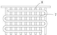
FIG. 2 is a schematic view of the mounting structure of the heat-dissipating coil and the heat-dissipating fins shown in FIG. 1;
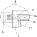
fig. 3 is an enlarged schematic view of a portion a shown in fig. 1.
Reference numbers in the figures: 1. a protective shell; 2. placing the plate; 3. a computer power supply body; 4. a water storage tank; 5. a fan; 6. a water pump; 7. a heat-dissipating coil pipe; 8. a heat dissipating fin; 9. a dust collection box; 10. a heat sink; 11. a filter plate; 12. a rectangular frame; 13. a motor; 14. a protection plate; 15. a chamber; 16. a screw; 17. a squeegee; 18. an exhaust fan; 19. and (7) a drying box.
Detailed Description
The present invention will be further described with reference to the accompanying drawings and embodiments.
Please refer to fig. 1, fig. 2 and fig. 3, wherein fig. 1 is a schematic structural diagram of a preferred embodiment of a safety device for a computer power supply according to the present invention; FIG. 2 is a schematic view of the mounting structure of the heat-dissipating coil and the heat-dissipating fins shown in FIG. 1; fig. 3 is an enlarged schematic view of a portion a shown in fig. 1. The power supply safety protection device for the computer comprises: the protection device comprises a protection shell 1, wherein two mounting blocks are fixedly mounted on the outer wall of one side of the protection shell 1, an internal thread hole is formed in each mounting block to fix the protection shell 1 on a case, a wire passing groove is further formed in the protection shell 1 to allow a power line to pass through, and a socket is further arranged on the protection shell 1 to enable a power plug to be connected with a power supply through the socket; the placing plate 2 is fixedly installed on the inner wall of the protective shell 1, the placing plate 2 is a honeycomb-shaped screen plate and is made of graphite plates, so that the heat conducting performance of the placing plate is good, the heat dissipation coil 7 can absorb heat in the computer power supply body 3 conveniently, a net-shaped mounting plate is further arranged at the bottom of the placing plate 2 to install the heat dissipation coil 7 and one end of the heat dissipation fin 8, and cold air blown out by the fan 5 can be blown out through meshes in the mounting plate to cool the heat dissipation fin 8; the computer power supply body 3 is fixedly arranged on the top of the placing plate 2; the water storage tank 4 is fixedly arranged on the inner wall of the bottom of the protective shell 1, and cooling liquid is arranged in the water storage tank 4 to cool the computer power supply body 3 through the flowing of the cooling liquid in the heat dissipation coil 7; the fan 5 is fixedly arranged on the inner wall of one side of the protective shell 1; the water pump 6 is fixedly arranged on the inner wall of the bottom of the protective shell 1; the heat dissipation coil 7 is fixedly installed at the bottom of the placing plate 2, a return pipe is further arranged on the heat dissipation coil 7, and the return pipe is fixedly connected with the top of the water storage tank 4 to return cooling liquid into the water storage tank 4; the heat dissipation coil pipe comprises heat dissipation fins 8, wherein the heat dissipation fins 8 are fixedly installed at the bottom of the heat dissipation coil pipe 7, an exhaust groove is formed in the outer wall of one side of the protective shell 1, and an ash baffle is arranged in the exhaust groove so that heat on the heat dissipation fins 8 is driven by the fan 5 to flow out through the exhaust groove; the dust collection box 9 is fixedly arranged on the outer wall of one side of the protective shell 1, the inner wall of the bottom of the dust collection box 9 is an inclined surface, and dust can conveniently leak out of the dust collection box 9 through the inclined surface; the heat dissipation groove 10 is formed in the top of the protective shell 1, and the heat dissipation groove 10 is formed in the top of the protective shell 1; the filter plate 11 is fixedly arranged on the inner wall of the heat dissipation groove 10; the rectangular frame 12 is fixedly arranged at the top of the protective shell 1; the motor 13 is fixedly arranged on the outer wall of one side of the rectangular frame 12, and a protective cover is arranged outside the motor 13 to prevent external dust from entering the motor 13 to damage the motor 13; the exhaust fan 18 is fixedly arranged at the top of the dust collection box 9, and a protective cover is also arranged outside the exhaust fan 18 to protect the exhaust fan 18; and the drying box 19 is arranged in the protective shell 1, the drying box 19 is a honeycomb-shaped net cage, and drying agents are filled in the net cage to prevent the damage of the computer power supply body 3 caused by external moisture.
Fixed mounting has guard plate 14 on the both sides inner wall of rectangle frame 12, chamber 15 has been seted up in the guard plate 14, rotate on the rectangle frame 12 and install screw rod 16, just the one end of screw rod 16 with the output shaft fixed connection of motor 13, just the screw rod 16 is located in the chamber 15, come to protect screw rod 16 through setting up guard plate 14 for at the in-process that screw rod 16 used, it has a large amount of dusts and leads to the damage of screw rod 16 to fall on the screw rod 16.
The threaded connection has the connecting block on the screw rod 16, the bottom of connecting block extends to the bottom of guard plate 14, just fixed mounting has scraper blade 17 on the bottom of connecting block, the bottom of scraper blade 17 with the top swing joint of filter 11, the top of connecting block is provided with the slider, slider and the top inner wall sliding connection of cavity 15 come to spacing the connecting block to can prevent that the connecting block from following the rotation of screw rod 16 and rotating together when the rotation of screw rod 16, and make the unable normal water translation of connecting block move.
Fixed mounting has the drinking-water pipe on the water inlet of water pump 6, the one end of drinking-water pipe extends to in the storage water tank 4, just fixed mounting has the connecting pipe on the delivery port of water pump 6, the top of connecting pipe with 7 fixed connection of heat dissipation coil pipe take out the coolant liquid in the storage water tank 4 through setting up drinking-water pipe and connecting pipe, come to cool down computer power supply body 3 through the flow of coolant liquid in heat dissipation coil pipe 7.
Fixed mounting has the ash discharge pipe on the output tube of air exhauster 18, the bottom of ash discharge pipe with the top fixed connection of dust collection box 9, just fixed mounting has the dust absorption pipe on the output of air exhauster 18, one of dust absorption pipe serves fixed mounting and has the dust absorption fill, the dust absorption fill with one side outer wall fixed connection of rectangle frame 12 is through setting up drain pipe and dust absorption fill, can be collected in sucking the dust collection box 9 with the dust that scraper blade 17 scraped.
An ash discharge groove is formed in the outer wall of one side of the dust collection box 9, an ash blocking plate is hinged to the outer wall of one side of the dust collection box 9, the ash blocking plate is fixedly connected with the dust collection box 9 through a first bolt, and after the dust collection box 9 is filled with the materials, the ash blocking plate can be opened to clean the dust in the dust collection box 9.
The utility model discloses a drying cabinet, including protective housing 1, drying cabinet 19, apron, cover board, drying cabinet 19 and the inner wall sliding connection of spout, just be provided with the apron on the outer wall of one side of protective housing 1, the apron with one side outer wall of drying cabinet 19 contacts, the apron with protective housing 1 passes through second bolt fixed connection, and the apron passes through two second bolt fixed connection with one side outer wall of protective housing 1 for can take drying cabinet 19 out through opening the apron, pour out the drier that loses activity in the drying cabinet 19, and change the drier.
The utility model provides a theory of operation for computer power safety device as follows:
when the computer power supply body 3 is installed, the protective shell 1 can be installed on a case for use through bolts and installation blocks, in the running process of a computer, the water pump 6 and the fan 5 are started simultaneously, so that the cooling liquid in the water storage tank 4 can be pumped out through the water pumping pipe and sent into the heat dissipation coil 7, the heat generated when the computer power supply body 3 is used is sucked through the flowing of the cooling liquid in the heat dissipation coil 7, the heat absorbed by the cooling liquid can be absorbed by the heat dissipation fins 8, the external air enters the protective shell 1 through the filter plate 11 and the drying box 19, the fan 5 blows out the air through meshes on the installation plate, the heat on the heat dissipation fins 8 is blown out of the case through the heat dissipation grooves, and the heat in the cooling liquid flows back into the water storage tank 4 through the return pipe after being absorbed, so that the computer power supply body 3 can be continuously dissipated heat, therefore, the damage of the computer power supply body 3 due to overhigh temperature can be prevented, in the using process, the filter plate 11 can filter outside dust, in addition, the drying agent in the drying box 19 can also absorb moisture in the air, so as to prevent the damage of the computer power supply body 3 due to dust and moisture in the outside air in the operation process of the fan 5, and when a large amount of dust is accumulated on the filter plate 11, the motor 13 and the exhaust fan 18 can be started, the motor 13 can rotate to drive the screw rod 16 to rotate, so that the scraper 17 can be driven to horizontally move through the screw thread action between the connecting blocks on the screw rod 16 and the scraper 17, further the dust attached on the filter plate 11 can be scraped by the scraper 17, and enters the dust collection box 9 for periodic collection under the dust absorption action of the exhaust fan 18, and then, only the dust baffle needs to be opened after the dust collection box 9 is filled, to clean the dust in the dust collecting box 9, so that the dust can be cleaned without frequently opening the box cover plate, and the use is more convenient.
Compared with the prior art, the utility model provides a be used for computer power safety device has following beneficial effect:
the utility model provides a safety protection device for computer power supply, through the setting of the water storage tank 4, the fan 5, the water pump 6, the heat dissipation coil pipe 7 and the heat dissipation fins 8, the cooling liquid that circulates can be used to cool the computer power supply body 3, thereby preventing the computer power supply body 3 from being damaged due to overhigh self temperature in the using process, the setting of the filter plate 11 and the drying box 19 can lead the computer power supply body 3 to be communicated with the outside, so that the heat can be better dissipated out of the protective shell 1, and the external dust and moisture can be prevented from entering the computer power supply body 3 to damage the computer power supply body 3, and the setting of the motor 13, the screw 16, the scraper 17, the exhaust fan 18 and the dust collection box 9 can clear up the dust attached on the filter plate 11, and send the dust into the dust collection box 9 through the exhaust fan 18, therefore, the filter plate 11 can be cleaned without opening the cover plate on the case for many times during ash removal, and the dust remover is convenient for people to use.
The above only is the embodiment of the present invention, not limiting the scope of the present invention, all the equivalent structures or equivalent processes of the present invention are used in the specification and the attached drawings, or directly or indirectly applied to other related technical fields, and the same principle is included in the protection scope of the present invention.
Claims (7)
1. A safety apparatus for a computer power supply, comprising:
a protective shell;
the placing plate is fixedly arranged on the inner wall of the protective shell;
the computer power supply body is fixedly arranged on the top of the placing plate;
the water storage tank is fixedly arranged on the inner wall of the bottom of the protective shell;
the fan is fixedly arranged on the inner wall of one side of the protective shell;
the water pump is fixedly arranged on the inner wall of the bottom of the protective shell;
the heat dissipation coil is fixedly arranged at the bottom of the placing plate;
the heat dissipation fins are fixedly arranged at the bottom of the heat dissipation coil;
the dust collection box is fixedly arranged on the outer wall of one side of the protective shell;
the heat dissipation groove is formed in the top of the protective shell;
the filter plate is fixedly arranged on the inner wall of the heat dissipation groove;
the rectangular frame is fixedly arranged at the top of the protective shell;
the motor is fixedly arranged on the outer wall of one side of the rectangular frame;
the exhaust fan is fixedly arranged at the top of the dust collection box;
a drying cabinet disposed within the protective housing.
2. The safety device for the computer power supply according to claim 1, wherein protection plates are fixedly mounted on the inner walls of two sides of the rectangular frame, a cavity is formed in each protection plate, a screw rod is rotatably mounted on the rectangular frame, one end of each screw rod is fixedly connected with an output shaft of the motor, and the screw rods are located in the cavities.
3. The computer power safety protection device according to claim 2, wherein a connecting block is threadedly mounted on the screw, the bottom of the connecting block extends to the bottom of the protection plate, a scraper is fixedly mounted on the bottom of the connecting block, and the bottom of the scraper is movably connected with the top of the filter plate.
4. The safety device for the computer power supply according to claim 1, wherein a water pumping pipe is fixedly installed at a water inlet of the water pump, one end of the water pumping pipe extends into the water storage tank, a connecting pipe is fixedly installed at a water outlet of the water pump, and the top end of the connecting pipe is fixedly connected with the heat dissipation coil pipe.
5. The safety protection device for the computer power supply according to claim 1, wherein an ash discharge pipe is fixedly installed on the output pipe of the exhaust fan, the bottom end of the ash discharge pipe is fixedly connected with the top of the dust collection box, a dust suction pipe is fixedly installed on the output end of the exhaust fan, a dust suction hopper is fixedly installed on one end of the dust suction pipe, and the dust suction hopper is fixedly connected with the outer wall of one side of the rectangular frame.
6. The safety protection device for computer power supply of claim 1, wherein an ash slot is opened on one side outer wall of the dust collection box, an ash blocking plate is hinged on one side outer wall of the dust collection box, and the ash blocking plate is fixedly connected with the dust collection box through a first bolt.
7. The computer power safety protection device according to claim 1, wherein a sliding groove is formed in an outer wall of one side of the protective shell, the drying box is slidably connected with an inner wall of the sliding groove, a cover plate is arranged on an outer wall of one side of the protective shell, the cover plate is in contact with an outer wall of one side of the drying box, and the cover plate is fixedly connected with the protective shell through a second bolt.
Priority Applications (1)
| Application Number | Priority Date | Filing Date | Title |
|---|---|---|---|
| CN202220227293.7U CN217238736U (en) | 2022-01-27 | 2022-01-27 | Safety protection device for computer power supply |
Applications Claiming Priority (1)
| Application Number | Priority Date | Filing Date | Title |
|---|---|---|---|
| CN202220227293.7U CN217238736U (en) | 2022-01-27 | 2022-01-27 | Safety protection device for computer power supply |
Publications (1)
| Publication Number | Publication Date |
|---|---|
| CN217238736U true CN217238736U (en) | 2022-08-19 |
Family
ID=82833119
Family Applications (1)
| Application Number | Title | Priority Date | Filing Date |
|---|---|---|---|
| CN202220227293.7U Expired - Fee Related CN217238736U (en) | 2022-01-27 | 2022-01-27 | Safety protection device for computer power supply |
Country Status (1)
| Country | Link |
|---|---|
| CN (1) | CN217238736U (en) |
-
2022
- 2022-01-27 CN CN202220227293.7U patent/CN217238736U/en not_active Expired - Fee Related
Similar Documents
| Publication | Publication Date | Title |
|---|---|---|
| CN113961057B (en) | Computer heat radiation structure | |
| CN111542208A (en) | Circulating air-draft type dust removal and heat dissipation device for electromechanical equipment | |
| CN211701076U (en) | Intelligent high-low voltage dry-type load box | |
| CN217238736U (en) | Safety protection device for computer power supply | |
| CN109688777A (en) | A kind of PLC control cabinet with cooling device | |
| CN210042677U (en) | Protective shell for frequency converter | |
| CN216774044U (en) | Dustproof low-voltage cabinet dispels heat | |
| CN211580478U (en) | Dust blockage preventing air cooling cabinet for electric power | |
| CN215732945U (en) | Intelligent bias power supply | |
| CN210980883U (en) | Mechanical ventilation cooling tower convenient to it is clean | |
| CN220341832U (en) | Heat radiation structure of electric power distribution cabinet | |
| CN215910335U (en) | Cooling water device for atomic absorption spectrophotometer | |
| CN212208167U (en) | Computer machine case heat dissipation mechanism | |
| CN219223456U (en) | Energy-saving steam heat exchange device | |
| CN215733466U (en) | Arc light protection device | |
| CN218336879U (en) | Electrical control equipment cabinet with multiple heat dissipation functions | |
| CN219513619U (en) | Self-adjusting heat dissipation type high-low voltage power distribution cabinet | |
| CN215814069U (en) | Computer heat abstractor | |
| CN216728398U (en) | Integrated circuit board dust removal equipment for integrated circuit testing | |
| CN219612454U (en) | Dustproof communication machine case equipment dispels heat | |
| CN116718032B (en) | Condenser for heat exchange system of telecommunication base station | |
| CN220754116U (en) | Distribution box for modern electric field | |
| CN216388989U (en) | Safe radiating dry-type transformer | |
| CN220822242U (en) | Electric power construction electric power fire prevention protection device | |
| CN216092903U (en) | Pre-filtering cooling device for pulse cloth tube dust filter |
Legal Events
| Date | Code | Title | Description |
|---|---|---|---|
| GR01 | Patent grant | ||
| GR01 | Patent grant | ||
| CF01 | Termination of patent right due to non-payment of annual fee |
Granted publication date: 20220819 |
|
| CF01 | Termination of patent right due to non-payment of annual fee |