CN217228135U - Four banding mechanisms - Google Patents
Four banding mechanisms Download PDFInfo
- Publication number
- CN217228135U CN217228135U CN202220003519.5U CN202220003519U CN217228135U CN 217228135 U CN217228135 U CN 217228135U CN 202220003519 U CN202220003519 U CN 202220003519U CN 217228135 U CN217228135 U CN 217228135U
- Authority
- CN
- China
- Prior art keywords
- sealing
- fixed
- vertical
- transverse
- shaft
- Prior art date
- Legal status (The legal status is an assumption and is not a legal conclusion. Google has not performed a legal analysis and makes no representation as to the accuracy of the status listed.)
- Active
Links
Images


Classifications
-
- Y—GENERAL TAGGING OF NEW TECHNOLOGICAL DEVELOPMENTS; GENERAL TAGGING OF CROSS-SECTIONAL TECHNOLOGIES SPANNING OVER SEVERAL SECTIONS OF THE IPC; TECHNICAL SUBJECTS COVERED BY FORMER USPC CROSS-REFERENCE ART COLLECTIONS [XRACs] AND DIGESTS
- Y02—TECHNOLOGIES OR APPLICATIONS FOR MITIGATION OR ADAPTATION AGAINST CLIMATE CHANGE
- Y02P—CLIMATE CHANGE MITIGATION TECHNOLOGIES IN THE PRODUCTION OR PROCESSING OF GOODS
- Y02P70/00—Climate change mitigation technologies in the production process for final industrial or consumer products
- Y02P70/50—Manufacturing or production processes characterised by the final manufactured product
Landscapes
- Package Closures (AREA)
Abstract
The utility model relates to the technical field of packaging equipment, especially, relate to a four banding mechanism, which comprises a frame, from last vertical sealing mechanism, horizontal sealing mechanism, tear a mouthful mechanism, vertical cutting mechanism and the horizontal cutting mechanism of down having set gradually in the frame, vertical sealing mechanism contains the symmetry and sets up the vertical sealing pivot in the frame, two vertical sealing corresponds the position in the pivot and all is fixed with the vertical sealing gyro wheel, two vertical sealing pivot is rotated by vertical sealing motor drive, horizontal sealing mechanism contains the horizontal sealing pivot that the symmetry set up in the frame, all be fixed with many horizontal sealing clamp splices in the horizontal sealing pivot, it contains the mouth pivot of tearing of setting in the frame to tear a mouthful mechanism, all be fixed with many in tearing the mouth pivot, evenly be fixed with a plurality of mouth knives that tear on the mouth clamp splice. The vertical removal filling material of wrapping bag of this device, very big reduction area to do not snatch fixed and step device, simple structure is suitable for the popularization.
Description
[ technical field ] A
The utility model relates to a equipment for packing technical field especially relates to a four banding mechanisms.
[ background of the invention ]
The horizontal full-automatic packaging machine adopts a filling mode of firstly making bags and then discharging, and a discharging opening can directly go deep into the bottom of the packaging bag for discharging, so that dust can be prevented from flying. If the powder particles are extremely fine and easy to be raised, a dust catcher suck-back device can be added at the upper sealing to suck a little powder absorbed by the bag opening. In addition, horizontal full automatic packaging machine has adopted horizontal seal to consolidate leakproofness. The design can completely solve the phenomenon of 'bounce', and the sealing performance of the seal is ensured to the maximum extent, so that the quality guarantee period of the product is effectively prolonged. Secondly, when producing mixed materials (such as instant soup, spare rib soup, chicken essence, monosodium glutamate, health care products, spices and other powder products), manufacturers often encounter the problem that generally, each brand of soup has a unique formula, and the right proportion of the formula determines the purity of the taste.
The vertical packaging equipment cannot increase stations on the equipment, so materials must be mixed in advance during filling to carry out blanking, but in actual production, the mixing ratio of an actual product is not consistent with the formula ratio due to the fact that the materials are mixed in advance or the materials are not uniform in the transmission process. The horizontal packaging equipment can meet the requirement of increasing stations of manufacturers due to the characteristic of transverse bag moving. In addition, the horizontal packaging equipment can be infinitely increased in stations theoretically. In the bag-moving process, different materials can be loaded into each bag one by one through different blanking devices. For example, one bag of instant soup stock contains powdery materials (such as salt and chicken essence) and granular materials (such as dehydrated vegetables and dehydrated beef), the first blanking device is used for feeding the powdery materials in the bag moving process of the horizontal packaging equipment, the second blanking device is used for feeding the granular materials after the bag is moved horizontally once, and the rest can be done in the same way. Referring to the horizontal full-automatic duplex bag packaging machine, we can also find that the material compatibility of the horizontal full-automatic packaging equipment is very strong.
However, the existing horizontal full-automatic packaging machine is not suitable for popularization and use because plastic films are hot-pressed into packaging bags in a horizontal transportation mode, the packaging bags are sequentially transported to quantitative blanking work stations to pot materials in proportion, the packaging bags filled with the materials are sealed and then cut into individual packaging bags, the individual packaging bags are collected after being made into bags in a horizontal stepping transportation mode, the individual packaging bags are canned after being canned, and the individual packaging bags are finally cut after being canned after being sealed after being canned.
The utility model discloses it is not enough to solve prior art and research and propose.
[ Utility model ] content
The utility model aims at overcoming the shortcoming of above-mentioned prior art, provide a four banding mechanisms.
The utility model discloses can realize through following technical scheme:
the utility model discloses a four-edge sealing mechanism, which comprises a frame, wherein a vertical sealing mechanism, a transverse sealing mechanism, a tearing mechanism, a vertical cutting mechanism and a transverse cutting mechanism are sequentially arranged on the frame from top to bottom, the vertical sealing mechanism comprises vertical sealing rotating shafts symmetrically arranged on the frame, two vertical sealing rollers are respectively fixed at corresponding positions on the vertical sealing rotating shafts, the two vertical sealing rotating shafts are driven by a vertical sealing motor to rotate, the transverse sealing mechanism comprises transverse sealing rotating shafts symmetrically arranged on the frame, a plurality of transverse sealing clamping blocks are respectively fixed on the transverse sealing rotating shafts, the tearing mechanism comprises tearing rotating shafts arranged on the frame, a plurality of tearing clamping blocks are respectively fixed on the tearing rotating shafts, a plurality of tearing knives are respectively fixed on the tearing clamping blocks, a knife holder rotating shaft is arranged at a position corresponding to the tearing rotating shafts on the frame, a plurality of tearing knife holders are respectively fixed on the knife holder rotating shafts, the vertical cutting mechanism comprises a vertical cutting rotating shaft arranged on a frame, the vertical cutting rotating shaft is also driven to rotate by a vertical sealing motor, a plurality of vertical cutting blades are uniformly fixed on the vertical cutting rotating shaft, vertical cutting blade seats are arranged at positions corresponding to the vertical cutting blades on the frame, the vertical cutting blade seats comprise mounting rods arranged on the frame and connected with the frame in a sliding mode, vertical cutting idler wheels connected with the mounting rods in a rotating mode are arranged at positions corresponding to the vertical cutting blades at the tail ends of the mounting rods, the transverse cutting mechanism comprises a transverse cutting main shaft arranged on the frame, transverse cutting cutters are fixed on the transverse cutting main shaft, transverse cutting auxiliary shafts are arranged at positions corresponding to the transverse cutting main shaft on the frame, transverse cutting blade seats are fixed on the auxiliary shafts, and the transverse sealing rotating shaft, the tearing rotating shaft, the blade seat rotating shaft and the transverse cutting main shaft are driven to rotate by corresponding servo motors. Two plastic films are overlapped and then conveyed between two vertical sealing rotating shafts, the vertical sealing rotating shafts are driven by a vertical sealing motor to rotate oppositely, vertical sealing rollers on the two vertical sealing rotating shafts rotate along with the vertical sealing rotating shafts, heating pipes on the vertical sealing rotating shafts heat the vertical sealing rotating shafts, when the two plastic films are overlapped and pass through the heated vertical sealing rollers, the vertical sealing rollers roll on the surfaces of the plastic films, when the plastic films move, the vertical sealing rollers roll on the two sides of the plastic films to heat and vertically seal the two sides of the plastic films, the plastic films continue to move downwards, when the plastic films pass through a transverse sealing mechanism, the transverse sealing rotating shafts are driven by a servo motor to rotate, because the heating pipes are arranged in the transverse sealing rotating shafts, transverse sealing clamping blocks are heated by the heating pipes, the transverse sealing clamping blocks rotate along with the transverse sealing rotating shafts, the two transverse sealing clamping blocks extrude the plastic films from the two sides, transverse heat sealing is formed between the two plastic films, and materials are slid into a packaging bag which is vertically sealed and transversely sealed by a blanking mechanism, the packaging bag filled with the materials continuously moves downwards, the packaging bag above the materials is sealed by the transverse sealing mechanism in a hot-pressing mode again, when the sealed materials pass through the position of the tearing mechanism, the tearing rotating shaft rotates, the tearing clamping block rotates along with the tearing rotating shaft, the tearing knife on the tearing clamping block rotates along with the tearing clamping block, when the packaging bag passes through the space between the tearing clamping block and the tearing knife seat, the packaging bag is cut on the packaging bag through the tearing knife, a notch easy to tear the packaging bag is formed at the hot-sealing position of the packaging bag, when the packaging bag passes through the vertical cutting mechanism after forming the notch, the vertical cutting rotating shaft rotates, the vertical cutting blade rotates along with the vertical cutting rotating shaft, when the packaging bag passes through the space between the vertical cutting blade and the vertical cutting roller, the vertical cutting blade rotates along with the vertical cutting rotating shaft, the vertical cutting blade vertically cuts the packaging bag from the middle of the hot-sealing position of the vertical sealing mechanism on the packaging bag, the packaging bag is cut into a plurality of packaging bags in the vertical direction, and then passes through the transverse cutting mechanism, the crosscut main shaft rotates, the crosscut cutter rotates along with the crosscut main shaft, the wrapping bag passes through between crosscut main shaft and the crosscut seat, the crosscut cutter cuts the wrapping bag with the crosscut seat cooperation, the crosscut cutter opens the wrapping bag along the centre of crosscut mechanism heat-seal position on the wrapping bag, the wrapping bag after cutting falls and collects in the workbin of below, this device can be on the plastic film packing position both sides erect and seal, the wrapping bag after the perpendicular seal carries out the crosscut, to wrapping bag filling material behind the crosscut bottom, carry out the top crosscut behind the filling material, cut along the heat-seal position behind the wrapping bag seal, cut into independent single packing with the wrapping bag, the vertical removal filling material of wrapping bag, very big reduction area, and do not snatch fixed and step-by-step device, moreover, the steam generator is simple in structure, and is suitable for popularization.
Preferably, a cold sealing mechanism is further arranged on the rack between the transverse sealing mechanism and the tearing mechanism, the cold sealing mechanism comprises two cold sealing rotating shafts symmetrically arranged on the rack, the two cold sealing rotating shafts are driven by corresponding servo motors to rotate, and a plurality of cold sealing clamping blocks are fixed on the two cold sealing rotating shafts. The wrapping bag is through violently sealing the mechanism heating horizontal heat seal back, and it is fixed to carry out the centre gripping to horizontal heat-seal position at the cold clamp splice through cold sealing mechanism, and the plastic film of further guaranteeing horizontal heat-seal position firmly can not loosen, can bear the weight of material.
Preferably, the transverse cutting auxiliary shaft is rotatably connected with the rack, a transverse cutting column is fixed on the transverse cutting auxiliary shaft, a buffer cylinder is further arranged on the rack, and the tail end of a piston rod of the buffer cylinder is connected with the transverse cutting column through a floating joint. Support the crosscut countershaft through buffer cylinder, during the wrapping bag crosscut, to the wrapping bag crosscut after through crosscut cutter and crosscut cutter seat extrusion, when the crosscut cutter took place the extrusion with the crosscut cutter seat, the crosscut cutter seat promoted the crosscut countershaft and rotates, the crosscut countershaft rotates the back and separates with the crosscut cutter by a small margin, supports the crosscut countershaft through buffer cylinder, can avoid crosscut cutter and crosscut cutter seat to take place rigid collision, can effectively prolong the life of crosscut cutter.
Preferably, a main chain wheel is fixed on the vertical sealing rotating shaft, a driven chain wheel is fixed on the vertical cutting rotating shaft at a position corresponding to the main chain wheel, the driven chain wheel is in winding connection with the main chain wheel through a chain, a tensioning device is further arranged on the rack, the tensioning device comprises a tensioning shaft fixed on the rack, a fixed shaft rotatably connected with the tensioning shaft is arranged on the tensioning shaft, the tail end of the fixed shaft is provided with the tensioning chain wheel rotatably connected with the fixed shaft, the tensioning chain wheel is meshed with the chain, a torsion spring is further fixed on the tensioning shaft, one end of the torsion spring is fixed with the tensioning shaft, and the other end of the torsion spring is fixed with the fixed shaft. Due to the action of the torsion spring, the torsion spring pushes the fixed shaft to rotate, the tensioning chain wheel extrudes the chain to tension the chain, and the vertical sealing motor can drive the vertical sealing rotating shaft and the vertical cutting rotating shaft to rotate.
Preferably, a spring in a compressed state is further arranged between the mounting rod and the frame.
Preferably, the vertical sealing rotating shaft and the horizontal sealing rotating shaft are both fixed with heating pipes.
Preferably, gears are fixed on the two vertical sealing rotating shafts, and the gears on the two vertical sealing rotating shafts are meshed with each other.
Preferably, gears are fixed on the two transverse sealing rotating shafts, and the gears on the two transverse sealing rotating shafts are meshed with each other.
Preferably, a gear is fixed on the tool apron rotating shaft, a gear is also fixed on the tearing rotating shaft, and the gear on the tearing rotating shaft is meshed with the gear on the tool apron rotating shaft.
Compared with the prior art, the utility model has the advantages that:
this device can be on the plastic film packing position both sides erect to seal, and the wrapping bag after the perpendicular seal is violently sealed, and the bottom violently seals the back and carries out the top violently to wrapping bag filling material, carries out the top violently sealing behind the filling material, cuts along heat-seal position behind the wrapping bag seal, cuts the wrapping bag into independent single packing, the vertical removal filling material of wrapping bag, very big reduction area to do not snatch fixed and step-by-step device, simple structure is suitable for the popularization.
[ description of the drawings ]
The following detailed description of embodiments of the present invention is provided with reference to the accompanying drawings, in which:
fig. 1 is a schematic structural view of the present invention;
FIG. 2 is an enlarged view of FIG. 1 at A;
fig. 3 is another schematic view of the angle structure of the present invention;
fig. 4 is a schematic view of a third angle structure of the present invention;
FIG. 5 is a schematic structural view of the vertical sealing mechanism of the present invention;
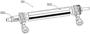
FIG. 6 is a schematic view of the structure of the horizontal sealing mechanism of the present invention;
FIG. 7 is a schematic structural view of the cold sealing mechanism of the present invention;
FIG. 8 is a schematic structural view of the tearing mechanism of the present invention;
FIG. 9 is a schematic view of the structure of the tear knife holder of the present invention;
fig. 10 is a schematic structural view of the vertical cutting mechanism of the present invention;
FIG. 11 is a schematic view of the vertical cutting roller structure of the present invention;
fig. 12 is a schematic structural view of a transverse cutting mechanism of the present invention;
in the figure: 1. a frame; 601. a vertical sealing mechanism; 6011. vertically sealing the motor; 6012. vertically sealing the rotating shaft; 6013. vertically sealing the roller; 602. a transverse sealing mechanism; 6021. a transverse sealing rotating shaft; 6022. transversely sealing the clamping block; 603. a cold sealing mechanism; 6031. cold sealing the rotating shaft; 6032. cold sealing the clamping block; 604. a tearing mechanism; 6041. a tear opening rotating shaft; 6042. a tearing clamping block; 6043. a tear-off knife; 6044. a tool apron rotating shaft; 6045. a tearing tool apron; 605. a vertical cutting mechanism; 6051. vertically cutting the rotating shaft; 6052. vertically cutting the blade; 6053. vertically cutting the roller; 6054. mounting a rod; 606. a transverse cutting mechanism; 6061. transversely cutting the main shaft; 6062. transversely cutting the auxiliary shaft; 6063. a transverse cutting knife; 6064. a transverse cutter seat; 6065. a buffer cylinder; 6066. a transverse cutting column; 607. a servo motor; 608. a chain; 609. tensioning the shaft; 610. a fixed shaft; 611. tensioning the chain wheel; 612. a torsion spring;
[ detailed description ] embodiments
The following detailed description of embodiments of the present invention is made with reference to the accompanying drawings:
as shown in fig. 1 to 12, the present invention discloses a four edge sealing mechanism, which comprises a frame 1, wherein a vertical sealing mechanism 601, a horizontal sealing mechanism 602, a tearing mechanism 604, a vertical cutting mechanism 605 and a horizontal cutting mechanism 606 are sequentially arranged on the frame 1 from top to bottom, the vertical sealing mechanism 601 comprises vertical sealing shafts 6012 symmetrically arranged on the frame 1, vertical sealing rollers 6013 are respectively fixed on corresponding positions of the two vertical sealing shafts 6012, the two vertical sealing shafts 6012 are driven by a vertical sealing motor 6011 to rotate, the horizontal sealing mechanism 602 comprises horizontal sealing shafts 6021 symmetrically arranged on the frame 1, a plurality of horizontal sealing clamping blocks 6022 are respectively fixed on the horizontal sealing shafts 6021, the tearing mechanism 604 comprises a tearing shaft 6041 arranged on the frame 1, a plurality of tearing clamping blocks 6042 are respectively fixed on the tearing shaft 6041, a plurality of tearing knives 6043 are respectively fixed on the tearing clamping blocks 6042, a knife holder 44 is arranged on the frame 1 corresponding to the tearing shaft 6041, a plurality of tearing knife seats 6045 are uniformly fixed on a knife seat rotating shaft 6044, a vertical cutting mechanism 605 comprises a vertical cutting rotating shaft 6051 arranged on the frame 1, the vertical cutting rotating shaft 6051 is also driven by a vertical sealing motor 6011 to rotate, a plurality of vertical cutting blades 6052 are uniformly fixed on the vertical cutting rotating shaft 6051, vertical knife seats are arranged on the frame 1 corresponding to the vertical cutting blades 6052, the vertical knife seats comprise mounting rods 6054 arranged on the frame 1 and connected with the frame 1 in a sliding way, vertical cutting rollers 6053 rotationally connected with the mounting rods 6054 are arranged at the tail ends of the mounting rods 6054 corresponding to the vertical cutting blades 6052, a transverse cutting mechanism 606 comprises a transverse cutting main shaft 6061 arranged on the frame 1, a transverse cutting knife 6063 is fixed on the transverse cutting main shaft 6061, a counter shaft 6062 is arranged on the frame 1 corresponding to the main shaft 6061, a transverse cutting knife seat 6064 is fixed on the counter shaft 6062, a transverse sealing rotating shaft 6021 and a tearing rotating shaft 6041, the tool apron rotating shaft 6044 and the transverse cutting main shaft 6061 are driven by corresponding servo motors 607 to rotate. Two plastic films are overlapped and then conveyed between two vertical sealing rotating shafts 6012, the vertical sealing motor 6011 drives the vertical sealing rotating shafts 6012 to rotate oppositely, vertical sealing rollers 6013 on the two vertical sealing rotating shafts 6012 rotate along with the vertical sealing rotating shafts 6012, heating pipes on the vertical sealing rotating shafts 6012 heat the vertical sealing rotating shafts 6012, when the two plastic films are overlapped and pass through the heated vertical sealing rollers 6013, the vertical sealing rollers 6013 roll on the surfaces of the plastic films, when the plastic films move, the vertical sealing rollers 6013 roll on the two sides of the plastic films to heat the vertical seals, the plastic films continue to move downwards, when the plastic films pass through the transverse sealing mechanism 602, the transverse sealing rotating shafts 6021 are driven to rotate by the servo motor 607, because the transverse sealing rotating shafts 1 are internally provided with heating pipes, the transverse sealing clamping blocks 6022 are heated by the heating pipes, the transverse sealing clamping blocks 6022 rotate along with the transverse sealing rotating shafts 6021, the two transverse sealing clamping blocks 6022 extrude the plastic films from the two sides, and form transverse heat sealing between the two plastic films 602, the material is slipped into the vertical and horizontal packaging bags through the blanking mechanism, the packaging bags filled with the material continue moving downwards, and the packaging bags above the material are sealed by the horizontal sealing mechanism 602 in a hot pressing way again, when the sealed material passes through the position of the mouth tearing mechanism 604, the mouth tearing rotating shaft 6041 rotates, the mouth tearing clamp 6042 rotates along with the mouth tearing rotating shaft 6041, the mouth tearing knife 6043 on the mouth tearing clamp 6042 rotates along with the mouth tearing clamp 6042, when the packaging bags pass between the mouth tearing clamp 6042 and the mouth tearing knife seat 6045, the packaging bags are cut on the packaging bags through the mouth tearing knife 6043, the cuts easy to tear the packaging bags are formed at the heat sealing position of the packaging bags, when the cuts are formed on the packaging bags and then pass through the vertical cutting mechanism 605, the vertical cutting rotating shaft 6051 rotates, the vertical cutting blade 6052 rotates along with the vertical cutting rotating shaft 6051, when the packaging bags pass between the vertical cutting blade 6052 and the vertical cutting roller 6053, because the vertical cutting blade 6052 rotates along with the vertical cutting rotating shaft 6051, the vertical cutting blade 6052 cuts the packaging bags from the middle heat sealing position of the packaging bags, after the packaging bags are cut into a plurality of packaging bags along the vertical direction, the packaging bags pass through a transverse cutting mechanism 606, a transverse cutting main shaft 6061 rotates, a transverse cutting cutter 6063 rotates along with the transverse cutting main shaft 6061, the packaging bags pass through between the transverse cutting main shaft 6061 and a transverse cutting cutter seat 6064, the transverse cutting cutter 6063 is matched with the transverse cutting cutter seat 6064 to cut the packaging bags along the middle of the heat sealing position of a transverse sealing mechanism 602 on the packaging bags, the cut packaging bags fall into a material box below for collection, the device can vertically seal two sides of the packaging position on a plastic film, transversely seal the vertically sealed packaging bags, transversely seal the packaging bags after transverse sealing at the bottom, transversely seal the top of the packaging bags after filling materials, cut the packaging bags into independent single packaging bags after sealing the packaging bags, vertically move the filling materials, greatly reduce the occupied area and have no grabbing, fixing and stepping devices, simple structure and is suitable for popularization.
Wherein, still be provided with cold seal mechanism 603 on the frame 1 between horizontal seal mechanism 602 and the tear mechanism 604, cold seal mechanism 603 contains the symmetry to the cold seal pivot 6031 of setting in frame 1, and two cold seal pivots 6031 are rotated by the drive of corresponding servo motor 607, all are fixed with a plurality of cold seals clamp 6032 on two cold seal pivots 6031. The wrapping bag is through the horizontal heat-seal back of the heating of horizontal seal mechanism 602, and it is fixed to carry out the centre gripping to horizontal heat-seal position at the cold clamp splice 6032 through cold seal mechanism 603, further guarantees that the plastic film of horizontal heat-seal position firmly can not loosen, can bear the weight of material.
The transverse cutting auxiliary shaft 6062 is rotatably connected with the rack 1, a transverse cutting column 6066 is fixed on the transverse cutting auxiliary shaft 6062, the rack 1 is further provided with a buffer cylinder 6065, and the tail end of a piston rod of the buffer cylinder 6065 is connected with the transverse cutting column 6066 through a floating joint. Support crosscut countershaft 6062 through buffer cylinder 6065, during the wrapping bag crosscut, to the wrapping bag crosscut after extrudeing through crosscut cutter 6063 and crosscut seat 6064, when crosscut cutter 6063 and crosscut seat 6064 take place the extrusion, crosscut seat 6064 promotes crosscut countershaft 6062 and rotates, crosscut countershaft 6062 small-amplitude rotation back and crosscut 6063 separation, support crosscut countershaft 6062 through buffer cylinder 6065, can avoid crosscut 6063 and crosscut seat 6064 to take place the rigidity collision, can effectively prolong crosscut 6063's life.
Wherein, a main chain wheel is fixed on the vertical sealing rotating shaft 6012, a secondary chain wheel is fixed on the vertical cutting rotating shaft 6051 at a position corresponding to the main chain wheel, the secondary chain wheel is connected with the main chain wheel in a winding way through a chain 608, the frame 1 is further provided with a tensioning device, the tensioning device comprises a tensioning shaft 609 fixed on the frame 1, the tensioning shaft 609 is provided with a fixed shaft 610 rotatably connected with the tensioning shaft 609, the tail end of the fixed shaft 610 is provided with a tensioning chain wheel 611 rotatably connected with the fixed shaft 610, the tensioning chain wheel 611 is meshed with the chain 608, the tensioning shaft 609 is further fixed with a torsion spring 612, one end of the torsion spring 612 is fixed with the tensioning shaft 609, and the other end of the torsion spring 612 is fixed with the fixed shaft 610. Due to the action of the torsion spring 612, the torsion spring 612 pushes the fixed shaft 610 to rotate, the tensioning chain wheel 611 is pressed with the chain 608 to tension the chain 608, and the vertical sealing motor 6011 can drive the vertical sealing rotating shaft 6012 and the vertical cutting rotating shaft 6051 to rotate.
Wherein, a spring in a compressed state is also arranged between the mounting rod 6054 and the frame 1.
Wherein, the vertical seal rotating shaft 6012 and the horizontal seal rotating shaft 6021 are both fixed with heating pipes.
Wherein, gears are fixed on the two vertical sealing rotating shafts 6012, and the gears on the two vertical sealing rotating shafts 6012 are engaged with each other.
Wherein, gears are fixed on the two horizontal sealing rotating shafts 6021, and the gears on the two horizontal sealing rotating shafts 6021 are engaged with each other.
Wherein, a gear is fixed on the tool holder rotating shaft 6044, a gear is also fixed on the tear opening rotating shaft 6041, and the gear on the tear opening rotating shaft 6041 is engaged with the gear on the tool holder rotating shaft 6044.
The foregoing is only a preferred embodiment of the present invention, and it should be noted that, for those skilled in the art, many changes, modifications, substitutions and variations can be made to the embodiments without departing from the technical principles of the present invention, and these changes, modifications, substitutions and variations should also be considered as the protection scope of the present invention.
Claims (9)
1. The utility model provides a four banding mechanisms, includes the frame, its characterized in that: the vertical sealing mechanism, the transverse sealing mechanism, the mouth tearing mechanism, the vertical cutting mechanism and the transverse cutting mechanism are sequentially arranged on the rack from top to bottom, the vertical sealing mechanism comprises vertical sealing rotating shafts symmetrically arranged on the rack, vertical sealing rollers are fixed at corresponding positions on the two vertical sealing rotating shafts, the two vertical sealing rotating shafts are driven by a vertical sealing motor to rotate, the transverse sealing mechanism comprises transverse sealing rotating shafts symmetrically arranged on the rack, a plurality of transverse sealing clamping blocks are fixed on the transverse sealing rotating shafts, the mouth tearing mechanism comprises a mouth tearing rotating shaft arranged on the rack, a plurality of mouth tearing clamping blocks are fixed on the mouth tearing rotating shaft, a plurality of mouth tearing knives are uniformly fixed on the mouth tearing clamping blocks, a knife holder rotating shaft is arranged at a position corresponding to the mouth tearing rotating shaft on the rack, a plurality of mouth tearing knife holders are uniformly fixed on the knife holder rotating shaft, the vertical cutting mechanism comprises a vertical cutting rotating shaft arranged on the rack, the vertical cutting rotating shaft is driven to rotate by a vertical sealing motor, a plurality of vertical cutting blades are uniformly fixed on the vertical cutting rotating shaft, vertical cutting blade seats are arranged at positions corresponding to the vertical cutting blades in the rack, each vertical cutting blade seat comprises an installation rod which is arranged on the rack and is in sliding connection with the rack, vertical cutting rollers which are connected with the installation rods in a rotating mode are arranged at positions corresponding to the vertical cutting blades at the tail ends of the installation rods, a transverse cutting mechanism comprises a transverse cutting main shaft arranged on the rack, a transverse cutting cutter is fixed on the transverse cutting main shaft, a transverse cutting auxiliary shaft is arranged at a position corresponding to the transverse cutting main shaft in the rack, a transverse cutting blade seat is fixed on the transverse cutting auxiliary shaft, and the transverse sealing rotating shaft, a tearing opening rotating shaft, a blade seat rotating shaft and the transverse cutting main shaft are driven to rotate by corresponding servo motors.
2. The four edge banding mechanism of claim 1, wherein: the frame between the transverse sealing mechanism and the tearing mechanism is also provided with a cold sealing mechanism, the cold sealing mechanism comprises two cold sealing rotating shafts which are symmetrically arranged on the frame, the two cold sealing rotating shafts are driven by corresponding servo motors to rotate, and a plurality of cold sealing clamping blocks are fixed on the two cold sealing rotating shafts.
3. The four edge banding mechanism of claim 1, wherein: the transverse cutting auxiliary shaft is rotationally connected with the rack, a transverse cutting column is fixed on the transverse cutting auxiliary shaft, a buffer cylinder is further arranged on the rack, and the tail end of a piston rod of the buffer cylinder is connected with the transverse cutting column through a floating joint.
4. The four edge banding mechanism of claim 1, wherein: erect and be fixed with the main sprocket in the pivot, erect and cut the pivot and correspond the position with the main sprocket and be fixed with from the sprocket, follow the sprocket and pass through chain and aforementioned main sprocket wiring, still be provided with straining device in the frame, straining device contains the straining shaft of fixing in the frame, be provided with the fixed axle of being connected with straining shaft rotation on the straining shaft, the fixed axle end is provided with the straining sprocket of being connected with the fixed axle rotation, straining sprocket and chain meshing, it still is fixed with the torsional spring on the straining shaft, torsional spring one end is fixed with the straining shaft, the torsional spring other end is fixed with the fixed axle.
5. The four edge banding mechanism of claim 1, wherein: and a spring in a compressed state is also arranged between the mounting rod and the rack.
6. The four edge banding mechanism of claim 1, wherein: heating pipes are fixed on the vertical sealing rotating shaft and the horizontal sealing rotating shaft.
7. The four edge banding mechanism of claim 1, wherein: gears are fixed on the two vertical sealing rotating shafts, and the gears on the two vertical sealing rotating shafts are meshed with each other.
8. The four edge banding mechanism of claim 1, wherein: gears are fixed on the two transverse sealing rotating shafts, and the gears on the two transverse sealing rotating shafts are meshed with each other.
9. The four edge banding mechanism of claim 1, wherein: the gear is fixed on the cutter holder rotating shaft, the gear is also fixed on the tearing opening rotating shaft, and the gear on the tearing opening rotating shaft is meshed with the gear on the cutter holder rotating shaft.
Priority Applications (1)
| Application Number | Priority Date | Filing Date | Title |
|---|---|---|---|
| CN202220003519.5U CN217228135U (en) | 2022-01-04 | 2022-01-04 | Four banding mechanisms |
Applications Claiming Priority (1)
| Application Number | Priority Date | Filing Date | Title |
|---|---|---|---|
| CN202220003519.5U CN217228135U (en) | 2022-01-04 | 2022-01-04 | Four banding mechanisms |
Publications (1)
| Publication Number | Publication Date |
|---|---|
| CN217228135U true CN217228135U (en) | 2022-08-19 |
Family
ID=82827631
Family Applications (1)
| Application Number | Title | Priority Date | Filing Date |
|---|---|---|---|
| CN202220003519.5U Active CN217228135U (en) | 2022-01-04 | 2022-01-04 | Four banding mechanisms |
Country Status (1)
| Country | Link |
|---|---|
| CN (1) | CN217228135U (en) |
-
2022
- 2022-01-04 CN CN202220003519.5U patent/CN217228135U/en active Active
Similar Documents
| Publication | Publication Date | Title |
|---|---|---|
| CN211108163U (en) | Liquid bagging and forming device | |
| CN209971690U (en) | Bag making machine for filling bag | |
| CN114435692B (en) | Four banding machine | |
| CN217228135U (en) | Four banding mechanisms | |
| CN2452892Y (en) | Machine for automatically packaging tea bag | |
| CN117002792A (en) | Cut meat packaging equipment | |
| CN112249450A (en) | Liquid seasoning package sealing equipment | |
| CN207985276U (en) | A kind of multi-functional closing device of diatom ooze production | |
| CN209305889U (en) | Pulvis automatic packaging machine | |
| CN217730983U (en) | Automatic packaging film packaging device | |
| CN216333019U (en) | Stretch film egg packaging machine | |
| CN114750458A (en) | Automatic wrapping bag production machine of bundling | |
| CN217256606U (en) | Broken collection device of rim charge | |
| CN216611813U (en) | Small bottle packaging machine | |
| CN111776327A (en) | Single package straw packaging machine | |
| CN217261160U (en) | Bag shearing device | |
| CN214085106U (en) | Automatic packaging, sealing and cutting system for blocky products | |
| CN218858860U (en) | Automatic sealing machine for food packaging | |
| CN215246021U (en) | Double-shear device | |
| CN218431914U (en) | Packaging machine capable of achieving rapid packaging | |
| CN220764806U (en) | Mouth dissolves membrane equipment for packing | |
| CN218751830U (en) | Automatic strip material cutting, edge sealing and packaging device | |
| CN210503315U (en) | Wrapping machine is used in carton processing | |
| CN216805986U (en) | Packaging equipment without support | |
| CN221341376U (en) | Full-automatic polystyrene foam packer |
Legal Events
| Date | Code | Title | Description |
|---|---|---|---|
| GR01 | Patent grant | ||
| GR01 | Patent grant |