CN217192797U - Multifunctional chamfering centering drilling and milling cutter for metal cutting - Google Patents
Multifunctional chamfering centering drilling and milling cutter for metal cutting Download PDFInfo
- Publication number
- CN217192797U CN217192797U CN202220223754.3U CN202220223754U CN217192797U CN 217192797 U CN217192797 U CN 217192797U CN 202220223754 U CN202220223754 U CN 202220223754U CN 217192797 U CN217192797 U CN 217192797U
- Authority
- CN
- China
- Prior art keywords
- chamfer
- drilling
- cutting edge
- milling cutter
- cutting
- Prior art date
- Legal status (The legal status is an assumption and is not a legal conclusion. Google has not performed a legal analysis and makes no representation as to the accuracy of the status listed.)
- Active
Links
Images


Abstract
The application relates to the technical field of milling cutters, in particular to a multifunctional chamfering centering drill milling cutter for metal cutting. The key points of the technical scheme are as follows: comprises a cutter head and a cutter handle; the cutter head is fixedly connected with the cutter handle, and a plurality of drilling chamfer parts are arranged on the cutter head; the drilling chamfering part comprises a peripheral edge and end teeth, the two ends of the peripheral edge are respectively connected with the end teeth and the tool handle, the end teeth are used for drilling and forming chamfering, and the peripheral edge is used for cutting a formed hole wall. This application has the function of the shaping efficiency of promotion part drilling.
Description
Technical Field
The application relates to the technical field of milling cutters, in particular to a multifunctional chamfering centering drill milling cutter for metal cutting.
Background
In the machine manufacturing industry, each part is almost always assembled into a machine from the initial manufacture to the final assembly without drilling holes, for example in the interconnection of parts, holes are made through which fasteners such as rivets, screws, etc. can be passed.
At present, in the machining of mechanical parts, the centering drill and the chamfering tool with single functions are generally adopted for machining, the chamfering tool is replaced to perform orifice chamfering after the centering drill is adopted for machining and drilling, so that burrs generated by drilling on parts are removed, and meanwhile, the chamfering tool also has a guiding effect and is convenient for part assembly.
Aiming at the related technology, the functions of the centering drill and the chamfering tool are single, the tool needs to be replaced in the whole drilling process, and the number of machining steps is large, so that the forming efficiency of part drilling needs to be improved.
SUMMERY OF THE UTILITY MODEL
In order to promote the shaping efficiency of part drilling, this application provides a multi-functional chamfer centering drill milling cutter for metal cutting.
The application provides a multi-functional chamfer centering bores milling cutter for metal cutting adopts following technical scheme:
a multifunctional chamfering and centering drilling and milling cutter for metal cutting comprises a cutter head and a cutter handle; the cutter head is fixedly connected with the cutter handle, and a plurality of drilling chamfer parts are arranged on the cutter head; the drilling chamfering part comprises a peripheral edge and end teeth, the two ends of the peripheral edge are respectively connected with the end teeth and the tool handle, the end teeth are used for drilling and forming chamfering, and the peripheral edge is used for cutting a formed hole wall.
By adopting the technical scheme, when a part is drilled, the cutter handle of the chamfering and centering drill milling cutter is clamped and fixed on a clamp of a machine tool, the part is fixed on the machine tool, and then a power supply is started, and the machine tool drives the chamfering and centering drill milling cutter to rotate; at the moment, the end teeth drill holes in positions to be drilled on the part, chamfers are formed, the peripheral edges cut and form hole walls through rotation, a positioning center hole, the chamfers and the hole wall milling can be machined at one time, tool changing frequency is reduced, and therefore the forming efficiency of part drilling is improved.
Preferably, one end of the end tooth, which is far away from the peripheral edge, is provided with a centering cutting edge, one side of the end tooth is provided with a chamfering cutting edge, one side of the peripheral edge is provided with a spiral cutting edge, one end of the chamfering cutting edge is connected with the centering cutting edge to form a nose, and the other end of the chamfering cutting edge is connected with the spiral cutting edge.
By adopting the technical scheme, when the chamfer centering drill milling cutter drills, the cutter point centers the position to be drilled on the part so as to facilitate the centering cutting edge to drill holes, then the spiral cutting edge performs cutting forming on the hole wall, and the edge of the cutting hole opening of the chamfer cutting edge performs chamfering.
Preferably, the number of the drilling chamfer parts is two, the tool bit is further provided with chip flutes, and the chip flutes are located between the two drilling chamfer parts.
By adopting the technical scheme, the number of the drilling chamfer parts is two, and the chip grooves are arranged between the two drilling chamfer parts, so that the width of the chip grooves is large, and part chips generated in the drilling process can be timely discharged.
Preferably, the chip groove includes guide section and chip removal section, the knife tip is located the one end of guide section, the other end of guide section with the chip removal section communicates.
By adopting the technical scheme, the part chips generated by drilling of the chamfering centering drill milling cutter enter the chip removal section through the guide section, and then are discharged in the hole, so that the blockage in the hole is reduced, and the drilling resistance is reduced.
Preferably, the helix angle of the helical cutting edge ranges from 25 ° to 40 °.
By adopting the technical scheme, the service life of the cutter can be reduced when the helix angle of the helical cutting edge is too large or too small, when the helix angle ranges from 25 degrees to 40 degrees, the cutting process of the helical cutting edge is stable, the cutting effect is good, and the surface quality of part machining is improved.
Preferably, the included angle between the chamfer cutting edges on the two drilling chamfers ranges from 60 ° to 120 °.
By adopting the technical scheme, when the included angle range between the chamfer cutting edges on the chamfer parts of the two drill holes is 60-120 degrees, the chamfer forming angle on the part is moderate, the chamfer has good guiding effect and assembly stability, and the part assembly is convenient.
Preferably, the width of the peripheral edge is in the range of 0.60mm to 0.65 mm.
By adopting the technical scheme, when the width range of the peripheral edge is between 0.60mm and 0.65mm, the peripheral edge has good cutting strength, meanwhile, the waste of materials can be reduced, the peripheral edge is not easy to break in the process of cutting and forming the hole wall, and the service life of the chamfer centering drill milling cutter is prolonged.
Preferably, the rake angle of the helical cutting edge ranges from 4 ° to 6 °.
Through adopting above-mentioned technical scheme, when the anterior angle scope of spiral cutting edge is 4 to 6, spiral cutting edge is comparatively sharp, the week sword cutting element of being convenient for, and spiral cutting edge has better cutting strength and heat-sinking capability simultaneously, has promoted the stability of this chamfer centering brill milling cutter drilling process.
In summary, the present application includes at least one of the following beneficial technical effects:
1. when the chamfering centering drill milling cutter drills a hole, the cutter point centers the position to be drilled on a part so as to facilitate the centering of the cutting edge to drill the hole, then the spiral cutting edge cuts and forms the hole wall, the chamfering edge of the cutting hole of the chamfering cutting edge forms the hole opening chamfering, a positioning center hole, the chamfering and the hole wall milling can be processed at one time, the cutter changing frequency is reduced, and therefore the forming efficiency of the part drilling is improved;
2. part scraps generated by the drilling of the chamfering centering drill milling cutter are guided to enter the scrap removal section through the guide section, and are discharged out of the hole in time, so that the blockage in the hole is reduced, and the drilling resistance is reduced;
3. the helix angle range of the chamfer centering drill milling cutter is 25-40 degrees, at the moment, the cutting process of the helical cutting edge is stable, the cutting effect is good, and the surface quality of part processing is improved.
Drawings
Fig. 1 is a schematic view of the overall structure of the chamfer centering drill-milling cutter of the present application.
Fig. 2 is a schematic view of a partial structure of a tool tip in the present application.
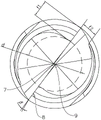
Fig. 3 is a schematic structural view of another view angle of the chamfer centering drill-milling cutter of the present application.
Description of reference numerals: 1. a cutter head; 2. a knife handle; 3. drilling a chamfer part; 4. a peripheral edge; 5. a helical cutting edge; 6. an end tooth; 7. centering the cutting edge; 8. chamfering the cutting edge; 9. a knife tip; 10. a chip pocket; 11. a guide section; 12. a chip removal section.
Detailed Description
The present application is described in further detail below with reference to figures 1-3.
The embodiment of the application discloses a multi-functional chamfer centering bores milling cutter for metal cutting. Referring to fig. 1, the chamfer centering drilling and milling cutter comprises a cutter head 1 and a cutter handle 2, wherein the outer diameter of the cutter head 1 is smaller than that of the cutter handle 2, the cutter head 1 and the cutter handle 2 are integrally formed, a plurality of drilling chamfer parts 3 are convexly arranged on the cutter head 1, and the drilling chamfer parts 3 are used for forming drilling and chamfering. Because the hard alloy has the characteristics of wear resistance, good toughness, high strength and the like, the tool bit 1 and the tool shank 2 are both made of the hard alloy.
In the present embodiment, the number of the drill chamfers 3 is two, the two drill chamfers 3 are arranged on the cutter head 1 at intervals, and the chip flutes 10 are formed between the two drill chamfers 3, so that the number of the chip flutes 10 is also two, and the width of the chip flutes 10 is large, thereby discharging the part chips generated during the drilling process in time.
Referring to fig. 2 and 3, the drilling chamfer portion 3 includes a peripheral edge 4 and an end tooth 6, the end tooth 6 has a plurality of triangular pyramidal faces, the peripheral edge 4 is in a thread shape, one end of the peripheral edge 4 is connected with the end tooth 6, and the other end is in transition connection with the tool shank 2. Here, the end teeth 6 of the two drilling chamfer parts 3 are connected with one end far away from the peripheral edge 4 to form a centering cutting edge 7, the side with the larger outer diameter of each end tooth 6 is provided with a chamfer cutting edge 8, the two chamfer cutting edges 8 are respectively connected with the centering cutting edge 7 to form a nose 9, the side with the larger outer diameter of the peripheral edge 4 is provided with a spiral cutting edge 5, and the spiral cutting edge 5 is connected with one end of the chamfer cutting edge 8 far away from the nose 9.
When the chamfering centering drill milling cutter rotates to drill, the tool nose 9 centers the position to be drilled on a part so as to facilitate the centering cutting edge 7 to drill, the spiral cutting edge 5 on the peripheral edge 4 cuts and forms a hole wall, and the chamfering cutting edge 8 on the end tooth 6 cuts the edge of a hole opening to form a hole opening chamfer. Therefore, the positioning center hole, the chamfer and the milling hole wall can be machined at one time, the tool changing frequency is reduced, the drilling process is not easy to be eccentric, the drilling accuracy is improved, and the forming efficiency of part drilling is improved.
In the present embodiment, the core diameter of the cutting head 1 is preferably 2.40mm, and the maximum thickness of the peripheral edge 4 in the core diameter direction is preferably 0.60mm, where the core diameter is defined as d and the thickness of the peripheral edge 4 is defined as f 1; the width of the peripheral edge 4 is in the range of 0.60mm to 0.65mm, and may be, for example, 0.60mm, 0.62mm, 0.63mm, or 0.65mm, and is preferably 0.62mm, and the width of the peripheral edge 4 is defined as f 2. At this time, the chamfered portion 3 has good cutting strength, and the peripheral edge 4 is less likely to break during the process of cutting the hole wall.
In addition, the rake angle of the helical cutting edge 5 ranges from 4 ° to 6 °, for example, it may be 4 °, 5 ° or 6 °, in the present embodiment, the rake angle of the helical cutting edge 5 is preferably 5 °, and herein, the rake angle of the helical cutting edge 5 is defined as β, at this time, the helical cutting edge 5 is sharp, and has good cutting strength and heat dissipation capability; meanwhile, the helix angle of the helical cutting edge 5 ranges from 25 ° to 40 °, and may be, for example, 25 °, 28 °, 30 °, 35 °, or 40 °, in this embodiment, the helix angle of the helical cutting edge 5 is preferably 30 °, at this time, the helical cutting edge 5 has a small resistance in the process of cutting a part, so that the peripheral edge 4 is convenient to cut the part, and thus the surface quality of the part machining is improved.
Referring back to fig. 1, in order to cut the formed orifice chamfer, the included angle between the chamfer cutting edges 8 on the two drill chamfer portions 3 ranges from 60 ° to 120 °, and may be, for example, 60 °, 70 °, 80 °, 90 °, 100 °, 110 °, or 120 °, etc., in the present embodiment, the included angle between the two chamfer cutting edges 8 is preferably 90 °, and herein, the included angle between the two chamfer cutting edges 8 is defined as α; at the moment, the chamfer angle forming angle on the part is moderate, and the chamfer has good guiding effect and assembly stability, so that the assembly of subsequent parts is facilitated.
In order to facilitate discharging of part scraps generated by drilling, the chip groove 10 comprises a guide section 11 and a chip discharge section 12, one end of the guide section 11 is communicated with the chip discharge section 12, the tool nose 9 is located at the end part of the guide section 11 far away from one end of the chip discharge section 12, and one end of the chip discharge section 12 far away from the guide section 11 is in surface transition connection with the tool shank 2, so that the possibility that the groove wall of the chip groove 10 blocks the part scraps to be discharged is reduced. Thereby, the part chips are guided into the chip removal section 12 through the guide section 11 and then discharged out of the drill hole, reducing clogging in the hole and thus reducing the resistance of the drill hole.
The implementation principle of the multifunctional chamfering centering drilling and milling cutter for metal cutting is as follows: when the chamfering centering drill milling cutter is used for drilling a part, the cutter handle 2 is clamped and fixed on a clamp of a machine tool, the part is fixed on the machine tool, and the position to be drilled on the part is centered through the cutter point 9 so as to facilitate the centering of a cutting edge 7 for drilling; and then, starting a power supply to enable the machine tool to drive the chamfering centering drill milling cutter to rotate, wherein the spiral cutting edge 5 on the peripheral edge 4 cuts the formed hole wall, and the chamfering cutting edge 8 on the end tooth 6 cuts the chamfer of the formed hole opening. In the drilling process, a cutter does not need to be replaced, the positioning center hole, the chamfer and the edge face can be machined at one time for milling, the drilling accuracy of the part is improved, the rejection rate of the part is reduced, and therefore the forming efficiency of the drilling of the part is improved.
The above embodiments are preferred embodiments of the present application, and the protection scope of the present application is not limited by the above embodiments, so: all equivalent changes made according to the structure, shape and principle of the present application shall be covered by the protection scope of the present application.
Claims (8)
1. The utility model provides a multi-functional chamfer centering bores milling cutter for metal cutting which characterized in that: comprises a cutter head (1) and a cutter handle (2);
the tool bit (1) is fixedly connected with the tool shank (2), and a plurality of drilling chamfer parts (3) are arranged on the tool bit (1);
drilling chamfer (3) are including all sword (4) and end tooth (6), all the both ends of sword (4) respectively with end tooth (6) and handle of a knife (2) are connected, end tooth (6) are used for drilling and shaping chamfer, all sword (4) are used for cutting shaping pore wall.
2. A multi-functional chamfer pilot drill milling cutter for metal cutting according to claim 1, wherein: keep away from end tooth (6) the one end of week sword (4) has centering cutting edge (7), one side of end tooth (6) has chamfer cutting edge (8), one side of week sword (4) has spiral cutting edge (5), the one end of chamfer cutting edge (8) with centering cutting edge (7) are connected and form knife tip (9), the other end of chamfer cutting edge (8) with spiral cutting edge (5) are connected.
3. A multi-functional chamfer pilot drill milling cutter for metal cutting according to claim 2, wherein: the drill bit is characterized in that the number of the drill hole chamfering portions (3) is two, the tool bit (1) is further provided with chip grooves (10), and the chip grooves (10) are located between the drill hole chamfering portions (3).
4. A multi-functional chamfer pilot drill mill for metal cutting according to claim 3, characterized in that: chip groove (10) are including guide segment (11) and chip removal section (12), knife tip (9) are located the one end of guide segment (11), the other end of guide segment (11) with chip removal section (12) are linked together.
5. A multi-functional chamfer pilot drill milling cutter for metal cutting according to claim 2, wherein: the helix angle of the helical cutting edge (5) ranges from 25 DEG to 40 deg.
6. A multi-functional chamfer pilot drill milling cutter for metal cutting according to claim 2, wherein: the angle between the chamfer cutting edges (8) on both drilling chamfers (3) ranges from 60 to 120 °.
7. A multi-functional chamfer pilot drill milling cutter for metal cutting according to claim 1, wherein: the width of the peripheral edge (4) ranges from 0.60mm to 0.65 mm.
8. A multi-functional chamfer pilot drill milling cutter for metal cutting according to claim 2, wherein: the rake angle of the helical cutting edge (5) ranges from 4 DEG to 6 deg.
Priority Applications (1)
| Application Number | Priority Date | Filing Date | Title |
|---|---|---|---|
| CN202220223754.3U CN217192797U (en) | 2022-01-26 | 2022-01-26 | Multifunctional chamfering centering drilling and milling cutter for metal cutting |
Applications Claiming Priority (1)
| Application Number | Priority Date | Filing Date | Title |
|---|---|---|---|
| CN202220223754.3U CN217192797U (en) | 2022-01-26 | 2022-01-26 | Multifunctional chamfering centering drilling and milling cutter for metal cutting |
Publications (1)
| Publication Number | Publication Date |
|---|---|
| CN217192797U true CN217192797U (en) | 2022-08-16 |
Family
ID=82794357
Family Applications (1)
| Application Number | Title | Priority Date | Filing Date |
|---|---|---|---|
| CN202220223754.3U Active CN217192797U (en) | 2022-01-26 | 2022-01-26 | Multifunctional chamfering centering drilling and milling cutter for metal cutting |
Country Status (1)
| Country | Link |
|---|---|
| CN (1) | CN217192797U (en) |
-
2022
- 2022-01-26 CN CN202220223754.3U patent/CN217192797U/en active Active
Similar Documents
| Publication | Publication Date | Title |
|---|---|---|
| CN210254406U (en) | Linear type three-point-fine tooth-shaped drilling and milling composite cutter | |
| CN205496646U (en) | Ream that drills and reams integration cutter | |
| CN217192797U (en) | Multifunctional chamfering centering drilling and milling cutter for metal cutting | |
| JP4468012B2 (en) | Rotating drill | |
| CN208758684U (en) | Clast drill bit | |
| CN218745062U (en) | Hard alloy drill | |
| CN217193102U (en) | Novel multi-tooth thread milling cutter | |
| CN111347087A (en) | Drill bit with automatic chip removal function | |
| CN212823865U (en) | Drilling and inserting type milling cutter | |
| CN220407201U (en) | Drilling reamer | |
| CN201988779U (en) | Vertical clamping milling blade for high-speed milling | |
| CN216858352U (en) | Special chamfer sword of foam absorbing material inclined plane processing | |
| CN210254407U (en) | Multi-blade tip-scale serrate drilling and milling composite cutter | |
| CN220612421U (en) | Quick waste removing numerical control cutter | |
| CN215431694U (en) | Inserted sheet formula PCD fluted drill | |
| CN211516185U (en) | Hard alloy drill bit | |
| CN217121890U (en) | Spiral end mill | |
| CN218639894U (en) | Three-edge spiral finish milling cutter | |
| CN218476054U (en) | Twist drill bit with micro-tooth structure | |
| CN220882727U (en) | Straight flute woodworking milling cutter | |
| CN217666661U (en) | Twist drill with ladder | |
| CN220533062U (en) | Novel flat bottom milling cutter | |
| CN217666703U (en) | Integrally formed cutter | |
| CN215238045U (en) | Coating ladder composite drill | |
| CN219746431U (en) | Step Kong Jianchi bores |
Legal Events
| Date | Code | Title | Description |
|---|---|---|---|
| GR01 | Patent grant | ||
| GR01 | Patent grant |