CN217183216U - Be fit for complementary large-span photovoltaic mounting system of farming light - Google Patents
Be fit for complementary large-span photovoltaic mounting system of farming light Download PDFInfo
- Publication number
- CN217183216U CN217183216U CN202220092303.0U CN202220092303U CN217183216U CN 217183216 U CN217183216 U CN 217183216U CN 202220092303 U CN202220092303 U CN 202220092303U CN 217183216 U CN217183216 U CN 217183216U
- Authority
- CN
- China
- Prior art keywords
- prestressed
- cable
- units
- cables
- chord
- Prior art date
- Legal status (The legal status is an assumption and is not a legal conclusion. Google has not performed a legal analysis and makes no representation as to the accuracy of the status listed.)
- Active
Links
Images


Classifications
-
- Y—GENERAL TAGGING OF NEW TECHNOLOGICAL DEVELOPMENTS; GENERAL TAGGING OF CROSS-SECTIONAL TECHNOLOGIES SPANNING OVER SEVERAL SECTIONS OF THE IPC; TECHNICAL SUBJECTS COVERED BY FORMER USPC CROSS-REFERENCE ART COLLECTIONS [XRACs] AND DIGESTS
- Y02—TECHNOLOGIES OR APPLICATIONS FOR MITIGATION OR ADAPTATION AGAINST CLIMATE CHANGE
- Y02E—REDUCTION OF GREENHOUSE GAS [GHG] EMISSIONS, RELATED TO ENERGY GENERATION, TRANSMISSION OR DISTRIBUTION
- Y02E10/00—Energy generation through renewable energy sources
- Y02E10/50—Photovoltaic [PV] energy
Landscapes
- Photovoltaic Devices (AREA)
Abstract
The utility model provides a large-span photovoltaic support system suitable for agricultural light complementation, which comprises two end supporting units, a middle supporting unit, a longitudinal stress unit and a transverse stabilizing unit, wherein the two end supporting units are symmetrically fixed on the ground, the two end supporting units are connected through two parallel longitudinal stress units, and the plurality of transverse stabilizing units are arranged between the two longitudinal stress units; the middle supporting unit is arranged between the two end supporting units and is connected with the longitudinal stress unit. The utility model discloses set up the splayed on the center pillar and support and undertake horizontal force, reduced stand bottom moment of flexure. The utility model provides a large-span photovoltaic support can vertically, transversely carry out the plane extension and form a system, can adapt to irregular land boundary and undulation topography. The utility model discloses the lower part headroom is big, can satisfy the requirement of agricultural construction, realizes real agricultural and photovoltaic power generation's dual function, has improved economy and social.
Description
Technical Field
The utility model belongs to the photovoltaic equipment field that suits with agricultural production, concretely relates to be fit for complementary large-span photovoltaic support of farming light.
Background
In the prior art, a large-span photovoltaic support system mostly adopts a photovoltaic support system consisting of solid web type steel beams, truss beams and net racks, but has the defects of large steel consumption, high cost, inconvenience in installation and transportation, discomfort in irregular shapes and the like. Therefore, the utility model provides a steel grid roof beam photovoltaic mounting system can overcome the shortcoming of above structure, provides the electric energy when not influencing pond, land production performance, can realize the comprehensive utilization in land.
The existing end support of the flexible support is generally connected with 2 upper chord prestressed cables by two independent steel columns, a steel support is arranged between the two steel columns and then connected with the 3 rd lower chord prestressed cable, the 3 cables are arranged in an inverted triangle, and a rigid tie rod or a cable truss is adopted between two rows of flexible supports to control the out-of-plane stability. The agricultural policy of the location of the project is not satisfied by the support form, and the support is large in steel consumption, high in cost and complex in construction and installation.
SUMMERY OF THE UTILITY MODEL
Arrange the interval little around in order to overcome current flexible support, and the problem that plane utilization is low, the utility model provides a be fit for complementary large-span photovoltaic support of farming light, the utility model discloses vertical large-span, horizontal interval satisfy the agricultural production machines operation requirement, and lateral stability is good.
The utility model adopts the technical proposal that:
a large-span photovoltaic bracket suitable for agricultural light complementation comprises two end supporting units, a middle supporting unit, a longitudinal stress unit and a transverse stabilizing unit, wherein the two end supporting units are symmetrically fixed on the ground, the two end supporting units are connected through the two parallel longitudinal stress units, and the plurality of transverse stabilizing units are arranged between the two longitudinal stress units; the middle supporting unit is arranged between the two end supporting units and connected with the longitudinal stress unit.
The end part supporting unit comprises two upright posts, two steel beams, splayed supports, an outer pull rod, two supporting short posts and an inter-cable supporting rod, the steel beams are arranged on the two upright posts, the steel beams are connected with the two upright posts through the splayed supports, the two supporting short posts are arranged on the steel beams, and the tops of the supporting short posts are connected with the steel beams through the inter-cable supporting rods; one end of the outer pull rod is connected to the top of the steel beam or the supporting short column, and the other end of the outer pull rod is obliquely fixed on the ground.
The steel beam is H-shaped or rectangular section steel, and two end parts of the steel beam are provided with anchoring points corresponding to the prestressed cables.
The middle supporting unit is in a door frame shape, and a splayed supporting rod is arranged in the door frame.
The longitudinal stress unit comprises an upper chord prestressed lower cable, an upper chord prestressed upper cable, a lower chord prestressed cable and prestressed inter-cable stay bars, wherein the upper chord prestressed lower cable, the upper chord prestressed upper cable and the lower chord prestressed cable are arranged in an inverted triangle and are connected through the prestressed inter-cable stay bars.
A plurality of linear supporting rods are arranged between the upper chord prestress lower cable and the upper chord prestress upper cable.
The upper chord prestressed cable and the lower chord prestressed cable which are composed of the upper chord prestressed lower cable and the upper chord prestressed upper cable are flexible cables, and the flexible cables are one or more of steel wire bundles, steel stranded wires, steel wire ropes, steel pull rods and hoisting belts.
The prestressed stay bar between cables is a triangular stay bar between cables.
The prestressed cable spacing device is characterized in that a plurality of prestressed cable spacing rods are arranged, and the longitudinal distance is 6-10 meters.
The transverse stabilizing unit comprises a first rigid tie rod, a second rigid tie rod and a diagonal pull rod; the upper chord prestressed cables of the front row and the lower chord prestressed cables of the rear row are connected through a rigid tie bar II, the lower chord prestressed cables of the front row and the lower chord prestressed cables of the rear row are connected through a rigid tie bar I, and the upper chord prestressed cables of the front row and the lower chord prestressed cables of the rear row are connected through a diagonal tie bar.
The utility model discloses the income effect who obtains does:
the utility model discloses in, vertical load is undertaken to the rigid frame of stand and girder steel constitution. In order to realize the support inclination angle, a short supporting column is arranged, and a splayed support is arranged on the upright column to bear the transverse horizontal force, so that the bending moment at the bottom of the upright column is reduced.
The utility model discloses a middle part supporting unit is with whole span grow, the utility model discloses can horizontal fore-and-aft extension, form space cable net structure after the broad commentaries on classics, space cable net structure dead weight is light, and structural efficiency is high, and is low with the steel volume.
The utility model discloses in, the stand of tip supporting element has carried out the selection of height according to the agricultural construction requirement to it is fixed to flare-outing through many outer pull rods, has guaranteed its stability and security.
After the extension the utility model discloses horizontal, longitudinal span is big, the lower part space is big, is adapted to the compound project application scene of photovoltaic of agricultural production machines, and the photovoltaic module lower extreme has had usable space bigger and bigger.
The utility model discloses the span is big, has practiced thrift the land used, and the plane extension of also being convenient for can adapt to irregular land used border and undulation topography better, easily carries out the photovoltaic pattern molding of earth plane view.
The following will be further described with reference to the accompanying drawings.
Drawings
Fig. 1 is the overall structure schematic diagram of the utility model after expansion.
Fig. 2 is a schematic structural diagram of the present invention.
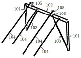
Fig. 3 is a schematic structural view of the end support unit.
Fig. 4 is a schematic structural view of the middle support unit.
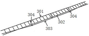
Fig. 5 is a schematic structural diagram of a longitudinal force-bearing unit.
Fig. 6 is a schematic structural view of a lateral stabilization unit.
In the figures, the reference numbers are: 1. an end support unit; 2. a middle support unit; 3. a longitudinal force-bearing unit; 4. a lateral stabilizing unit;
101. a column; 102. a steel beam; 103. splayed supporting; 104. an outer pull rod; 105. a support stub; 106. an inter-cable stay;
301. an upper chord prestress lower rope; 302. an upper chord prestress upper rope; 303. a lower chord prestressed cable; 304. a prestressed stay bar between cables;
401. a first rigid tie bar; 402. a second rigid tie bar; 403. a diagonal tie rod.
Detailed Description
The utility model discloses a be fit for complementary large-span photovoltaic mounting system of farming light to make further explanation below through drawing and embodiment, the drawing and the example are with the utility model discloses technical scheme implements under as the prerequisite, gives detailed implementation mode and concrete operation process.
In order to overcome the problem that current flexible support front and back row interval is little, and plane utilization is low, the utility model provides a be fit for complementary large-span photovoltaic support of farming light as shown in fig. 1-6, the utility model discloses vertical large-span, horizontal interval satisfy agricultural production machines operation requirement, and horizontal stability is good.
A large-span photovoltaic bracket suitable for agricultural light complementation comprises two end supporting units 1, a middle supporting unit 2, longitudinal stress units 3 and transverse stabilizing units 4, wherein the two end supporting units 1 are symmetrically fixed on the ground, the end supporting units 1 are connected through the two parallel longitudinal stress units 3, and the plurality of transverse stabilizing units 4 are arranged between the two longitudinal stress units 3; the middle supporting unit 2 is arranged between the two end supporting units 1 and is connected with the longitudinal force bearing unit 3.
The utility model provides a pair of be fit for complementary large-span photovoltaic support of farming light can be vertical, transversely carry out the plane extension, form a system, can adapt to irregular ground boundary and undulation topography betterly, easily carry out the photovoltaic pattern molding of ground plane view. And simultaneously, will the utility model provides a pair of be fit for complementary large-span photovoltaic support of farming light and carry out standard module ization, practice thrift the land used like this, the plane extension of being convenient for can adapt to irregular land used border and relief topography betterly. And simultaneously, the utility model provides a pair of be fit for complementary large-span photovoltaic support height of farming light enough, the interval is enough, can satisfy the requirement of agricultural construction.
The utility model discloses in, tip supporting element 1 highly enough, the lower part headroom is big, satisfies the requirement of agricultural construction, realizes real agricultural and photovoltaic power generation's dual function, improves the economic benefits and the social of project.
The utility model discloses a space cable net structure, the dead weight is light, and structural efficiency is high, and is low with the steel volume.
The utility model discloses in, as shown in fig. 2, tip supporting element 1 is used for supporting vertical atress unit 3, and middle part supporting element 2 supports vertical atress unit 3, has lengthened the length between two tip supporting elements 1 simultaneously, guarantees that its span satisfies the agricultural demand. The utility model discloses in, horizontal stable unit 4 guarantees that vertical atress unit 3 is stable at horizontal atress. The photovoltaic board is established the utility model provides an on the support, in photovoltaic power generation, can not influence the agricultural land used of lower extreme.
The utility model discloses stability is high, horizontal and longitudinal span is big, the lower part space is big, has adapted to the compound project application scene of photovoltaic of agricultural production machines for the photovoltaic module lower extreme has bigger and bigger usable space.
Example 2:
based on embodiment 1, in this embodiment, preferably, the end supporting unit 1 includes two columns 101, two steel beams 102, splayed supports 103, outer tie rods 104, two supporting short columns 105 and inter-cable bracing rods 106, where the steel beams 102 are arranged on the two columns 101, the steel beams 102 are connected with the two columns 101 through the splayed supports 103, the two supporting short columns 105 are arranged on the steel beams 102, and the tops of the supporting short columns 105 are connected with the steel beams 102 through the inter-cable bracing rods 106; the outer tie rod 104 has one end connected to the top of the steel beam 102 or the support post 105 and the other end fixed on the ground in an outward inclined manner.
Preferably, the steel beam 102 is a section steel with an H-shaped or rectangular cross section, and two ends of the steel beam 102 are provided with anchoring points corresponding to the prestressed cables.
As shown in fig. 3, the center pillar 101, the steel beam 102 and the splayed support 103 of the present invention form a rigid frame to bear vertical load, and the horizontal load is borne by the outward-facing outer tie rod 104; a support stub 105 of the upper chord prestressed upper cable is provided for realizing the bracket inclination.
Preferably, the middle supporting unit 2 is in a shape of a door frame, and a splayed supporting rod is arranged in the door frame.
As shown in fig. 4, the middle supporting unit 2 of the present invention is substantially the same as the end supporting unit 1, and the middle supporting unit 2 is different from the end supporting unit 1 in that there is no outer pull rod 104 in the middle supporting unit 2. The middle supporting unit 2 comprises a vertical column 101, a steel beam 102, a splayed support 103, a support short column 105 and an inter-cable support rod 106, and the vertical column 101 and the steel beam 102 of the middle supporting unit 2 form a rigid frame to bear vertical load; a supporting short column 105 of the middle supporting unit 2 of the upper chord prestress upper cable 301 is arranged for realizing the bracket inclination angle; splayed supports 103 are arranged in a plurality of rows at intervals in the transverse direction to bear transverse horizontal force, and the bottom bending moment of the upright post 101 is reduced.
As shown in fig. 4 and 5, the utility model discloses high strength prestressed pipe pile is chooseed for use to the center pillar 101, is fixed in place soil through hammering or static pressure, can also adopt the great other forms of vertical rigidity.
Preferably, the longitudinal force-bearing unit 3 comprises an upper-chord prestressed lower cable 301, an upper-chord prestressed upper cable 302, a lower-chord prestressed cable 303 and an inter-prestressed cable stay 304, wherein the upper-chord prestressed lower cable 301, the upper-chord prestressed upper cable 302 and the lower-chord prestressed cable 303 are arranged in an inverted triangle and are connected through the inter-prestressed cable stay 304.
Preferably, a plurality of linear supporting rods are arranged between the upper chord prestressed lower cable 301 and the upper chord prestressed upper cable 302.
Preferably, the upper chord prestressed cable and the lower chord prestressed cable 303 which are composed of the upper chord prestressed lower cable 301 and the upper chord prestressed upper cable 302 are flexible cables, and the flexible cables are one or more of steel wire bundles, steel stranded wires, steel wire ropes, steel pull rods and hoisting belts.
Preferably, the prestressed inter-cable stay 304 is a triangular inter-cable stay.
Preferably, the prestressed inter-cable stay bars 304 are multiple and longitudinally spaced by 6-10 meters.
As shown in fig. 5, in the present invention, the longitudinal force-bearing unit 3 is an inverted triangle arrangement of an upper chord prestressed lower cable 301, an upper chord prestressed upper cable 302 and a lower chord prestressed cable 303; the support inclination angle is realized by the high-low arrangement of the upper chord prestressed lower cable 301 and the upper chord prestressed upper cable 302; the prestressed stay bars 304 between cables are arranged at a reasonable interval, so that the structure becomes a longitudinal space cable truss system, and the vertical bearing capacity and the deformation resistance are improved. The interval of the triangular stay bars (the prestressed stay bars 304 between cables) is determined by calculation according to the stress of the cable truss. The inclination angle of the upper chord 2 prestressed cables is arranged to adapt to the inclination angle of the photovoltaic module.
The utility model discloses in, flexible cables such as steel wire bundle, steel strand wires, wire rope or hoist and mount area can be chooseed for use to three prestressed cables of upper chord prestressing force lower cable 301, upper chord prestressing force upper cable 302, lower chord prestressing force cable 303, can also select the steel strand wires, the wire rope etc. of different cross-section specifications according to the pulling force variation that the cable receives respectively. An inclined inhaul cable is arranged at the prestressed cable, and prestressed steel bars or steel pipes are selected as the inhaul cable. And the transverse stabilizing units 4 among the longitudinal stress units 3 are used for determining the spacing and the number according to the actual project calculation.
Preferably, said lateral stabilizing unit 4 comprises a first rigid tie bar 401, a second rigid tie bar 402 and a diagonal tie bar 403; the upper chord prestressed cables in the front row and the lower chord prestressed cables in the rear row are connected through a rigid tie bar II 402, the lower chord prestressed cables 303 in the front row and the lower chord prestressed cables in the rear row are connected through a rigid tie bar I401, and the upper chord prestressed cables in the front row and the lower chord prestressed cables in the rear row are connected through a diagonal tie bar 403.
As shown in fig. 6, the lateral stabilizing unit 4 of the present invention is a rigid tie bar two 402 between the upper chord prestressed cables of the front and rear row space cable trusses, a rigid tie bar one 401 between the lower chord prestressed cables 303, and a steel tie bar (diagonal tie bar 403) between the upper chord prestressed cables of the front row and the lower chord prestressed cables 303 of the rear row, so as to form a lateral stabilizing truss between the space cable trusses and improve the whole deformation resistance of the structure.
In the utility model, each rod piece is treated by corrosion prevention, wherein the corrosion prevention can be realized in a factory, thereby not only ensuring the quality of the corrosion prevention, but also saving the time of on-site corrosion prevention construction; and simultaneously, the utility model discloses simple to operate, each part is very low to haulage vehicle's requirement, is particularly suitable for the inconvenient region of traffic, for example mountain area. The utility model discloses can adapt to various irregular planes in a flexible way, can stride across the pond and do photovoltaic system on water, also can stride across large-area pond, mud flat or river to and the hillside fields, provide the electric energy when not influencing pond, soil productivity, can realize the comprehensive utilization in soil.
As shown in fig. 1, the utility model provides a pair of be fit for the mutual concatenation of complementary large-span photovoltaic support of farming light, form the mounting system of type rectangle array structure, can also increase a suitable complementary large-span photovoltaic support of farming light of standard and move about freely and quickly two direction quantity, form denser subassembly and arrange, improve land area utilization.
The utility model provides a tip supporting element 1 comprises 2 stands 101 and a girder steel 102 rigid frame, for improving girder steel 102 atress performance, reducing stand 101 bottom moment of flexure and set up the splayed support 103, sets up the supporting short column 105 of being connected with last quarter prestressed cable in girder steel 102 relevant position, for the rigidity that improves tip supporting element 1, sets up multichannel pull rod 104 and consolidates stand 101.
The utility model discloses well vertical atress unit 3 is inverted triangle-shaped by 3 prestressed cables and arranges, and photovoltaic module passes through the dedicated connection spare and is connected with 2 upper chord prestressed cables, and the prestressed cable sets up prestressed cable and supports 304 between vertical interval 6~10 meters, forms the cable truss system in space, improves structure bearing capacity and anti deformability.
The utility model discloses well horizontal stable unit 4 supports 304 departments between vertical atress unit 3's prestressing cable, sets up rigidity tie rod 401, rigidity tie rod two 402 and diagonal angle pull rod 403, constitutes plane truss system, forms multichannel plane stable truss between transversely, sets up the string and is connected about stand and the plane stable truss at horizontal tip, improves photovoltaic mounting system's stability ability.
The diagonal tie bar 403 of the present invention is preferably a tie bar. The medium-large span of the utility model is 30m-60m, in the utility model, the preferable range is 35m, 40m, 45m, 50m, 55m, 58m, 60 m. The utility model discloses the height of center pillar 101 is 1.5m at least, the utility model discloses in, preferably 1.8m, 2m, 2.1m, 2.3m, 2.5m, 3m, 3.5 m.
The utility model discloses well stand 101 can select to use high strength prestressed pipe pile, steel column or reinforced concrete prefabricated column, and stand 101 top sets up built-in fitting and girder steel 102 welded connection, bottom and sets up the staple bolt and connect splayed bracing 103.
The utility model discloses not restricted by length shape, not restricted by the slope, adopt the net cable structure, practiced thrift steel. The whole support can flexibly adapt to various irregular planes and has high stability.
The utility model discloses well each component adopts the assemblization, comes to establish prestressing force at overall structure kind through string prestressing cable about the stretch-draw during the construction, the utility model discloses can accomplish at on-the-spot rapid Assembly, can provide great rigidity and span after the structure takes shape, the fine condition that adapts to agricultural machines and tools and use, the whole quality of structure is lighter, is convenient for transport and store, can improve the comprehensive utilization efficiency in soil, has stronger actual meaning.
What has not been described in detail in the present invention is the prior art or can be realized by the prior art, and the embodiment of the present invention is only a better embodiment of the present invention, which is not intended to limit the scope of the present invention. All equivalent changes and decorations according to the content of the claims of the present invention should be regarded as the technical scope of the present invention. The device structure and the method steps not described in detail in the present invention are prior art, and no further explanation will be given in the present invention.
Claims (10)
1. The utility model provides a be fit for complementary large-span photovoltaic mounting system of farming light which characterized in that: the device comprises end supporting units (1), a middle supporting unit (2), longitudinal stress units (3) and transverse stabilizing units (4), wherein the number of the end supporting units (1) is two, the end supporting units are symmetrically fixed on the ground, the end supporting units (1) are connected through the two parallel longitudinal stress units (3), and the plurality of the transverse stabilizing units (4) are arranged between the two longitudinal stress units (3); the middle supporting unit (2) is arranged between the two end supporting units (1) and is connected with the longitudinal stress unit (3).
2. The large-span photovoltaic mounting system suitable for agricultural light complementation according to claim 1, wherein: the end supporting unit (1) comprises two upright columns (101), two steel beams (102), splayed supports (103), an outer pull rod (104), supporting short columns (105) and inter-cable supporting rods (106), wherein the steel beams (102) are arranged on the two upright columns (101), the steel beams (102) are connected with the two upright columns (101) through the splayed supports (103), the two supporting short columns (105) are arranged on the steel beams (102), and the tops of the supporting short columns (105) are connected with the steel beams (102) through the inter-cable supporting rods (106); one end of the outer pull rod (104) is connected to the top of the steel beam (102) or the supporting short column (105), and the other end of the outer pull rod is obliquely fixed on the ground.
3. The large-span photovoltaic mounting system suitable for agricultural light complementation according to claim 2, wherein: the steel beam (102) is H-shaped or rectangular section steel, and two end parts of the steel beam (102) are provided with anchoring points corresponding to the prestressed cables.
4. The large-span photovoltaic mounting system suitable for agricultural light complementation according to claim 1, wherein: the middle supporting unit (2) is in a door frame shape, and a splayed supporting rod is arranged in the door frame.
5. The large-span photovoltaic mounting system suitable for agricultural light complementation according to claim 1, wherein: the longitudinal stress unit (3) comprises an upper chord prestressed lower cable (301), an upper chord prestressed upper cable (302), a lower chord prestressed cable (303) and an inter-prestressed cable stay bar (304), wherein the upper chord prestressed lower cable (301), the upper chord prestressed upper cable (302) and the lower chord prestressed cable (303) are arranged in an inverted triangle and are connected through the inter-prestressed cable stay bar (304).
6. The large-span photovoltaic mounting system suitable for agricultural light complementation according to claim 5, wherein: a plurality of linear support rods are arranged between the upper chord prestress lower cable (301) and the upper chord prestress upper cable (302).
7. The large-span photovoltaic mounting system suitable for agricultural light complementation according to claim 5, wherein: the upper chord prestressed cable and the lower chord prestressed cable (303) which are composed of the upper chord prestressed lower cable (301) and the upper chord prestressed upper cable (302) are flexible cables, and the flexible cables are one or more of steel wire bundles, steel stranded wires, steel wire ropes, steel pull rods and hoisting belts.
8. The large-span photovoltaic mounting system suitable for agricultural light complementation according to claim 5, wherein: the prestressed stay bar (304) between cables is a triangular stay bar between cables.
9. The wide-span photovoltaic mounting system suitable for agricultural light complementation according to claim 7, wherein: the prestressed inter-cable support rods (304) are multiple and longitudinally spaced at 6-10 m intervals.
10. The large-span photovoltaic mounting system suitable for agricultural light complementation according to claim 1, wherein: the transverse stabilizing unit (4) comprises a first rigid tie rod (401), a second rigid tie rod (402) and a diagonal tie rod (403); the upper chord prestressed cables in the front row and the lower chord prestressed cables in the rear row are connected through a rigid tie bar II (402), the lower chord prestressed cables (303) in the front row and the lower chord prestressed cables in the rear row are connected through a rigid tie bar I (401), and the upper chord prestressed cables in the front row and the lower chord prestressed cables in the rear row are connected through a diagonal tie bar (403).
Priority Applications (1)
| Application Number | Priority Date | Filing Date | Title |
|---|---|---|---|
| CN202220092303.0U CN217183216U (en) | 2022-01-14 | 2022-01-14 | Be fit for complementary large-span photovoltaic mounting system of farming light |
Applications Claiming Priority (1)
| Application Number | Priority Date | Filing Date | Title |
|---|---|---|---|
| CN202220092303.0U CN217183216U (en) | 2022-01-14 | 2022-01-14 | Be fit for complementary large-span photovoltaic mounting system of farming light |
Publications (1)
| Publication Number | Publication Date |
|---|---|
| CN217183216U true CN217183216U (en) | 2022-08-12 |
Family
ID=82735573
Family Applications (1)
| Application Number | Title | Priority Date | Filing Date |
|---|---|---|---|
| CN202220092303.0U Active CN217183216U (en) | 2022-01-14 | 2022-01-14 | Be fit for complementary large-span photovoltaic mounting system of farming light |
Country Status (1)
| Country | Link |
|---|---|
| CN (1) | CN217183216U (en) |
Cited By (1)
| Publication number | Priority date | Publication date | Assignee | Title |
|---|---|---|---|---|
| CN117792235A (en) * | 2024-02-16 | 2024-03-29 | 三亚豺特光伏科技有限公司 | High-altitude photovoltaic power generation method for cultivated land and photovoltaic power generation suspension cable |
-
2022
- 2022-01-14 CN CN202220092303.0U patent/CN217183216U/en active Active
Cited By (2)
| Publication number | Priority date | Publication date | Assignee | Title |
|---|---|---|---|---|
| CN117792235A (en) * | 2024-02-16 | 2024-03-29 | 三亚豺特光伏科技有限公司 | High-altitude photovoltaic power generation method for cultivated land and photovoltaic power generation suspension cable |
| CN117792235B (en) * | 2024-02-16 | 2024-05-14 | 三亚豺特光伏科技有限公司 | High-altitude photovoltaic power generation method for cultivated land and photovoltaic power generation suspension cable |
Similar Documents
| Publication | Publication Date | Title |
|---|---|---|
| CN114865995B (en) | Be fit for complementary super large-span cable structure photovoltaic mounting system of fishing light | |
| CN216904730U (en) | Suspension cable type photovoltaic support | |
| CN101597918B (en) | Prestressed giant brace-frame structure | |
| CN205647362U (en) | Large -span prestressing force cable photovoltaic support | |
| CN217183216U (en) | Be fit for complementary large-span photovoltaic mounting system of farming light | |
| CN113241998A (en) | Flexible photovoltaic fixed bolster of prestressing force | |
| CN115483877A (en) | Angle truss type purlin multirow photovoltaic module cable bearing structure | |
| CN205792385U (en) | Prestressed girder rope adjustable angle photovoltaic support | |
| CN216599481U (en) | Large-span small-deformation flexible photovoltaic support system | |
| CN215734096U (en) | Novel photovoltaic module flexible support | |
| CN2835408Y (en) | Cable-truss-supported multi-span continuous orthogonal saddle-shape cable net | |
| CN114598248A (en) | Novel space cable net photovoltaic support system | |
| CN217883275U (en) | Large-span prestressed cable truss photovoltaic support system | |
| CN213029327U (en) | Multi-span greenhouse grape cultivation frame | |
| CN217483014U (en) | Large-span cable-stayed stable flexible photovoltaic support system | |
| CN215222073U (en) | Triangular space prestressed cable truss photovoltaic support system | |
| CN212533734U (en) | Cable buckle integrated tower | |
| CN114337482A (en) | Long purlin single-bearing-cable vertically and horizontally fixedly connected flexible photovoltaic support system and construction method | |
| CN201821299U (en) | Photovoltaic power station support | |
| CN211458248U (en) | Grape suspension system | |
| CN220673658U (en) | Framework type photovoltaic flexible support structure | |
| CN2835407Y (en) | Cable-supported multi-span continuous oblique-crossing saddle-shape cable net | |
| CN218672667U (en) | Photovoltaic flexible cable-stayed anchor cable system | |
| CN218581125U (en) | Plant independent column scaffold with overpass | |
| CN220475647U (en) | Large-span flexible photovoltaic bracket |
Legal Events
| Date | Code | Title | Description |
|---|---|---|---|
| GR01 | Patent grant | ||
| GR01 | Patent grant |