CN217166208U - Cylinder stripping mechanism for mold - Google Patents
Cylinder stripping mechanism for mold Download PDFInfo
- Publication number
- CN217166208U CN217166208U CN202220732798.9U CN202220732798U CN217166208U CN 217166208 U CN217166208 U CN 217166208U CN 202220732798 U CN202220732798 U CN 202220732798U CN 217166208 U CN217166208 U CN 217166208U
- Authority
- CN
- China
- Prior art keywords
- fixedly connected
- cylinder
- die
- plate
- connecting plate
- Prior art date
- Legal status (The legal status is an assumption and is not a legal conclusion. Google has not performed a legal analysis and makes no representation as to the accuracy of the status listed.)
- Active
Links
Images

Landscapes
- Mounting, Exchange, And Manufacturing Of Dies (AREA)
Abstract
The utility model relates to a cylinder stripping mechanism for mould, including the work panel, work panel bottom both sides fixedly connected with backup pad, the central position fixedly connected with die at work panel top, the inside stripping hole of having seted up of die, the connecting plate with backup pad fixed connection is installed to work panel below, and the pivot of being connected is rotated with the backup pad to the connecting plate below, pivot central symmetry fixedly connected with cam, cam top sliding connection have the mounting panel, a plurality of fixed columns of mounting panel top fixedly connected with, fixed column top fixedly connected with fixed plate, fixed plate top symmetry fixedly connected with cylinder, cylinder top fixedly connected with stripping piece, the fixed column outside is located the cover between mounting panel and the connecting plate and is equipped with the spring, pivot one end fixedly connected with rotates the wheel. The utility model discloses, simple structure not only, convenient to use, the security is high moreover, is worth using and promoting.
Description
Technical Field
The utility model relates to a mould processing technology field especially relates to a cylinder takes off material mechanism for mould.
Background
The die is various dies and tools for obtaining required products by injection molding, blow molding, extrusion, die casting or forging forming, smelting, stamping and other methods in industrial production. In short, a mold is a tool used to make a shaped article, the tool being composed of various parts, and different molds being composed of different parts, which effect shaping of the article primarily through changes in the physical state of the material being shaped.
The workpiece is placed at the top of the female die and can be bent and molded through the punch stamping, and the workpiece can be adhered to the female die after being stamped through the punch, so that the workpiece is inconvenient to take off. Therefore, the utility model provides a cylinder takes off material mechanism for mould.
SUMMERY OF THE UTILITY MODEL
The utility model provides a cylinder takes off material mechanism for mould has solved the technical problem among the prior art.
The utility model provides a scheme as follows of above-mentioned technical problem: a cylinder stripping mechanism for a die comprises a working panel, wherein supporting plates are fixedly connected to two sides of the bottom of the working panel, supporting rods are fixedly connected to two sides of the top of the working panel, a top plate is fixedly connected to the top of the supporting rods, hydraulic cylinders are fixedly connected to the central position of the bottom of the top plate symmetrically, a stamping plate is fixedly connected to the bottom of the hydraulic cylinders, a male die is fixedly connected to the bottom of the stamping plate, a female die is fixedly connected to the central position of the top of the working panel, stripping holes are formed in the female die, a connecting plate fixedly connected with the supporting plates is mounted below the working panel, a rotating shaft rotatably connected with the supporting plates is mounted below the connecting plate, cams are fixedly connected to the central position of the rotating shaft symmetrically, a mounting plate is slidably connected above the cams, a plurality of fixing columns are fixedly connected to the top of the mounting plate, a fixing plate is fixedly connected to the tops of the fixing columns, and cylinders are symmetrically and fixedly connected to the tops of the fixing plates, the cylinder top fixedly connected with takes off the material piece, the fixed column outside is located the cover and is equipped with the spring between mounting panel and the connecting plate, pivot one end fixedly connected with rotates the wheel.
On the basis of the technical scheme, the utility model discloses can also do following improvement.
Furthermore, the bottom of the supporting plate is fixedly connected with a foot pad.
Furthermore, positioning plates are fixedly connected to two sides of the top of the female die.
Furthermore, the number of the fixing columns is three.
Further, the spring is a compression spring.
Further, the surface of the rotating wheel is provided with anti-skidding threads.
Further, the rotating wheel is made of 304 stainless steel.
Advantageous effects
Compared with the prior art, the utility model, the advantage that has does:
1. the rotating wheel is rotated to drive the rotating shaft and the cam to rotate, so that the cam presses the mounting plate, the mounting plate compresses the spring to lift the fixing plate, and the stripping block can eject a workpiece at the top of the female die, so that the structure is simple, the use is convenient, and the safety is high;
2. the distance between the stripping block and the fixed plate can be adjusted by arranging the air cylinder, the extension of the air cylinder is favorable for the stripping block to eject out the workpiece more quickly, and the applicability is strong.
Drawings
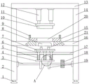
Fig. 1 is a schematic structural view of a cylinder stripping mechanism for a mold according to an embodiment of the present invention;
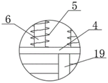
FIG. 2 is an enlarged schematic structural view of the position A in the cylinder stripping mechanism for the mold provided in FIG. 1;
fig. 3 is a schematic perspective structure view of a female die in the cylinder stripping mechanism for the die provided in fig. 1.
In the drawings, the components represented by the respective reference numerals are listed below:
1. a foot pad; 2. a support plate; 3. a rotating shaft; 4. mounting a plate; 5. a spring; 6. fixing a column; 7. a fixing plate; 8. stripping the material block; 9. positioning a plate; 10. a male die; 11. stamping the plate; 12. a hydraulic cylinder; 13. a top plate; 14. a support bar; 15. a female die; 16. a working panel; 17. a connecting plate; 18. a rotating wheel; 19. a cam; 20. material stripping holes; 21. and a cylinder.
Detailed Description
The invention will be further described with reference to specific embodiments shown in the drawings.
As shown in FIGS. 1-3, the utility model provides a cylinder stripping mechanism for a mold, which comprises a working panel 16, wherein two sides of the bottom of the working panel 16 are fixedly connected with supporting plates 2, two sides of the top of the working panel 16 are fixedly connected with supporting rods 14, the top of the supporting rods 14 is fixedly connected with a top plate 13, the central position of the bottom of the top plate 13 is symmetrically and fixedly connected with hydraulic cylinders 12, the bottom of the hydraulic cylinders 12 is fixedly connected with a stamping plate 11, the bottom of the stamping plate 11 is fixedly connected with a convex die 10, the central position of the top of the working panel 16 is fixedly connected with a concave die 15, stripping holes 20 are arranged in the concave die 15, a workpiece is placed at the top of the concave die 15, a positioning plate 9 can play a role in positioning the workpiece, the hydraulic cylinder 12 is started to drive the stamping plate 11 to descend, the convex die 10 can stamp and bend the workpiece, a connecting plate 17 fixedly connected with the supporting plates 2 is arranged below the working panel 16, a rotating shaft 3 rotatably connected with the supporting plate 2 is installed below the connecting plate 17, a cam 19 is symmetrically and fixedly connected with the center of the rotating shaft 3, a mounting plate 4 is slidably connected above the cam 19, a plurality of fixing columns 6 are fixedly connected with the top of the mounting plate 4, a fixing plate 7 is fixedly connected with the top of the fixing columns 6, a cylinder 21 is symmetrically and fixedly connected with the top of the fixing plate 7, the distance between the stripping block 8 and the fixing plate 7 can be adjusted by arranging the cylinder 21, the cylinder 21 is extended to facilitate the stripping block 8 to eject a workpiece more quickly, the applicability is strong, the stripping block 8 is fixedly connected with the top of the cylinder 21, a spring 5 is sleeved outside the fixing columns 6 between the mounting plate 4 and the connecting plate 17, a rotating wheel 18 is fixedly connected with one end of the rotating shaft 3, the rotating shaft 3 and the cam 19 can be driven to rotate by rotating the rotating wheel 18, so that the cam 19 presses the mounting plate 4, and the mounting plate 4 compresses the spring 5 to lift the fixing plate 7, the stripper block 8 can eject the workpiece from the top of the die 15.
Preferably, the bottom of the supporting plate 2 is fixedly connected with a foot pad 1, and the foot pad 1 can play a supporting role.
Preferably, the positioning plates 9 are fixedly connected to two sides of the top of the female die 15, and the positioning plates 9 can position the workpiece.
Preferably, the number of the fixing columns 6 is three, the fixing columns 6 are in sliding connection with the connecting plate 17, the guiding effect is achieved, and the stability of the three fixing columns 6 is good.
Preferably, the spring 5 is a compression spring, and a certain gap is formed between the coils of the compression spring, so that the spring contracts and deforms when being subjected to an external load, and deformation energy is stored.
Preferably, the surface of the rotating wheel 18 is provided with anti-skid threads, and the anti-skid threads can increase the friction force between the hand of the operator and the rotating wheel 18, thereby facilitating the rotation of the rotating wheel 18.
Preferably, the rotating wheel 18 is made of 304 stainless steel, and the 304 stainless steel has the characteristics of good processability and high toughness.
The utility model discloses a concrete theory of operation and application method do: place the work piece at die 15 top, locating plate 9 can play the effect of location to the work piece, start hydraulic cylinder 12 and drive punching press board 11 and descend, terrace die 10 can bend the shaping to the work piece punching press, rotate and rotate wheel 18, can drive pivot 3 and cam 19 and rotate, thereby make cam 19 push mounting panel 4, mounting panel 4 compression spring 5 makes fixed plate 7 rise, stripping block 8 can be ejecting with the work piece at die 15 top, simple structure not only, high durability and convenient use, and the security is high, can adjust the distance between stripping block 8 and the fixed plate 7 through setting up cylinder 21, cylinder 21 extension is favorable to stripping block 8 more fast ejecting with the work piece, the suitability is strong.
The above is only a preferred embodiment of the present invention, and it should be noted that for those skilled in the art, without departing from the structure of the present invention, several modifications and improvements can be made, which will not affect the utility of the invention and the utility of the patent.
Claims (7)
1. The utility model provides a cylinder takes off material mechanism for mould, includes work panel (16), its characterized in that, work panel (16) bottom both sides fixedly connected with backup pad (2), work panel (16) top both sides fixedly connected with bracing piece (14), bracing piece (14) top fixedly connected with roof (13), central point symmetry fixedly connected with pneumatic cylinder (12) of roof (13) bottom, pneumatic cylinder (12) bottom fixedly connected with punching press board (11), punching press board (11) bottom fixedly connected with terrace die (10), central point fixedly connected with die (15) at work panel (16) top, die (15) inside has seted up takes off material hole (20), work panel (16) below is installed and is taken off connecting plate (17) with backup pad (2) fixed connection, and pivot (3) of being connected with backup pad (2) rotation are installed to connecting plate (17) below, pivot (3) central symmetry fixedly connected with cam (19), cam (19) top sliding connection has mounting panel (4), a plurality of fixed columns (6) of mounting panel (4) top fixedly connected with, fixed column (6) top fixedly connected with fixed plate (7), fixed plate (7) top symmetry fixedly connected with cylinder (21), cylinder (21) top fixedly connected with take off material piece (8), the cover is equipped with spring (5) between fixed column (6) outside being located mounting panel (4) and connecting plate (17), pivot (3) one end fixedly connected with rotates wheel (18).
2. The cylinder stripping mechanism for the mold according to claim 1, characterized in that a foot pad (1) is fixedly connected to the bottom of the supporting plate (2).
3. The cylinder stripping mechanism for the die according to claim 2, wherein the positioning plates (9) are fixedly connected to two sides of the top of the female die (15).
4. The cylinder stripping mechanism for the die as claimed in claim 1, characterized in that the number of the fixing posts (6) is three.
5. The cylinder stripper mechanism for moulds according to claim 4, characterised in that the spring (5) is a compression spring.
6. The cylinder stripper mechanism for moulds according to claim 4, characterised in that the surface of the rotating wheel (18) is provided with anti-slip threads.
7. The cylinder stripper mechanism for molds according to claim 6, wherein said rotating wheel (18) is made of 304 stainless steel.
Priority Applications (1)
| Application Number | Priority Date | Filing Date | Title |
|---|---|---|---|
| CN202220732798.9U CN217166208U (en) | 2022-03-30 | 2022-03-30 | Cylinder stripping mechanism for mold |
Applications Claiming Priority (1)
| Application Number | Priority Date | Filing Date | Title |
|---|---|---|---|
| CN202220732798.9U CN217166208U (en) | 2022-03-30 | 2022-03-30 | Cylinder stripping mechanism for mold |
Publications (1)
| Publication Number | Publication Date |
|---|---|
| CN217166208U true CN217166208U (en) | 2022-08-12 |
Family
ID=82745604
Family Applications (1)
| Application Number | Title | Priority Date | Filing Date |
|---|---|---|---|
| CN202220732798.9U Active CN217166208U (en) | 2022-03-30 | 2022-03-30 | Cylinder stripping mechanism for mold |
Country Status (1)
| Country | Link |
|---|---|
| CN (1) | CN217166208U (en) |
-
2022
- 2022-03-30 CN CN202220732798.9U patent/CN217166208U/en active Active
Similar Documents
| Publication | Publication Date | Title |
|---|---|---|
| CN1927497A (en) | Cold stamping composite mold | |
| CN201026670Y (en) | Aluminium alloyed door/window profile press machine | |
| CN112620417A (en) | High-precision bending die capable of being formed flexibly | |
| CN217166208U (en) | Cylinder stripping mechanism for mold | |
| CN215902651U (en) | Be used for fashioned precision mould of high-quality terminal installed part | |
| CN213645613U (en) | Drawing die for metal shell workpieces | |
| CN201058355Y (en) | Extrusion mold with versatility | |
| CN212072829U (en) | Mold ejection device | |
| CN109013831B (en) | Punching die capable of automatically ejecting workpiece | |
| CN2685059Y (en) | Hydraulic press | |
| CN217393425U (en) | Stamping equipment that hot stamping forming used | |
| CN220426533U (en) | Stamping die for stamping metal products | |
| CN111842646A (en) | Automobile fender mould | |
| CN213162899U (en) | Stamping type forging die for metal workpiece | |
| CN221289248U (en) | Composite forming die | |
| CN220259449U (en) | High-temperature forging die | |
| CN214556640U (en) | Punching die for household appliances | |
| CN220920512U (en) | Hyperbolic aluminum plate die sinking mechanism | |
| CN214813919U (en) | Electronic product mold capable of rapidly changing mold | |
| CN215431117U (en) | Ultra-precise progressive die | |
| CN220198841U (en) | Special unloading structure for motor vehicle license plate word pressing machine | |
| CN210435177U (en) | Stamping die capable of automatically taking part | |
| CN220658955U (en) | Precision hardware stamping die | |
| CN219309810U (en) | High-precision stamping control system convenient for quick discharging | |
| CN203184381U (en) | Double-acting fine adjustment forming mechanism |
Legal Events
| Date | Code | Title | Description |
|---|---|---|---|
| GR01 | Patent grant | ||
| GR01 | Patent grant |