CN217166177U - Workpiece fixing tool for stamping die - Google Patents
Workpiece fixing tool for stamping die Download PDFInfo
- Publication number
- CN217166177U CN217166177U CN202220168972.1U CN202220168972U CN217166177U CN 217166177 U CN217166177 U CN 217166177U CN 202220168972 U CN202220168972 U CN 202220168972U CN 217166177 U CN217166177 U CN 217166177U
- Authority
- CN
- China
- Prior art keywords
- collecting box
- stamping die
- plate
- work piece
- fixing tool
- Prior art date
- Legal status (The legal status is an assumption and is not a legal conclusion. Google has not performed a legal analysis and makes no representation as to the accuracy of the status listed.)
- Active
Links
Images


Classifications
-
- Y—GENERAL TAGGING OF NEW TECHNOLOGICAL DEVELOPMENTS; GENERAL TAGGING OF CROSS-SECTIONAL TECHNOLOGIES SPANNING OVER SEVERAL SECTIONS OF THE IPC; TECHNICAL SUBJECTS COVERED BY FORMER USPC CROSS-REFERENCE ART COLLECTIONS [XRACs] AND DIGESTS
- Y02—TECHNOLOGIES OR APPLICATIONS FOR MITIGATION OR ADAPTATION AGAINST CLIMATE CHANGE
- Y02P—CLIMATE CHANGE MITIGATION TECHNOLOGIES IN THE PRODUCTION OR PROCESSING OF GOODS
- Y02P70/00—Climate change mitigation technologies in the production process for final industrial or consumer products
- Y02P70/10—Greenhouse gas [GHG] capture, material saving, heat recovery or other energy efficient measures, e.g. motor control, characterised by manufacturing processes, e.g. for rolling metal or metal working
Landscapes
- Press Drives And Press Lines (AREA)
Abstract
The utility model discloses a frock is fixed to work piece for stamping die, its structure includes the collecting box and removes the subassembly, through placing the work piece in the upper end of ejector pin, the work piece shelters from the inside inductor of recess, then drive two-way screw rod through controller starter motor and rotate, make slider mutual movement, it makes the pinch-off blades press from both sides the work piece to drive the connecting plate, and make pressure sensor work under the effect of atress board, then the motor stop work, the frictional layer presss from both sides the work piece tightly, the work piece of having solved current most stamping die all carries out manual fixing through the manual work in the aspect of fixing, not only inefficiency, still waste operating time, and a large amount of residues appear easily in present stamping process, do not carry out the problem that effectual collection leads to follow-up clearance difficulty.
Description
Technical Field
The utility model relates to a fixed technical field of work piece especially relates to a frock is fixed to work piece for stamping die.
Background
The stamping die is a special process equipment for processing materials (metal or nonmetal) into parts (or semi-finished products) in cold stamping, and is called cold stamping die (commonly called cold stamping die). Stamping is a press working method in which a die mounted on a press is used to apply pressure to a material at room temperature to cause separation or plastic deformation of the material, thereby obtaining a desired part. The material for making the stamping die comprises steel, hard alloy, steel bonded hard alloy, zinc-based alloy, low-melting point alloy, aluminum bronze, high polymer material and the like. The material for manufacturing the stamping die is mostly steel, and the types of the commonly used die working parts include carbon tool steel, low alloy tool steel, high carbon high chromium or medium chromium tool steel, medium carbon alloy steel, high speed steel, matrix steel, hard alloy, steel bonded hard alloy and the like.
Need be equipped with the fixed frock of work piece when stamping die uses, but the work piece of present most stamping die all carries out manual fixing through the manual work in the aspect of fixed, and not only inefficiency still wastes operating time, and a large amount of residues appear easily in present stamping process moreover, do not carry out effectual collection and lead to follow-up clearance difficulty.
SUMMERY OF THE UTILITY MODEL
Technical problem to be solved
In order to overcome the prior art not enough, the workpiece fixing tool for the stamping die is provided so as to solve the problems that workpieces of most stamping dies are manually fixed through manpower in the aspect of fixing, the efficiency is low, the working time is wasted, a large amount of residues are easy to occur in the existing stamping process, and the subsequent cleaning difficulty is caused due to the fact that effective collection is not performed.
(II) technical scheme
The utility model discloses a following technical scheme realizes: the utility model provides a work piece fixing tool for stamping die, including the collecting box, the collecting box side is equipped with the controller, two-way screw rods are arranged inside the collecting box, and the two-way screw rod side is connected with the collecting box through bearing two, two-way screw rod one side is equipped with the gear, and connects through the belt between the gear, the collecting box side is equipped with the backup pad, the backup pad upper end is equipped with the motor, and the motor output end is connected with one two-way screw rod, the two-way screw rod inside symmetry is equipped with the removal subassembly, two-way screw rod middle part is equipped with the ejector pin and is connected with the collecting box, the collecting box top is equipped with the recess, the recess is inside to be equipped with the inductor;
the movable assembly comprises a sliding block arranged at the bottom end and connected with a bidirectional screw rod, the upper end of the sliding block is connected with a connecting plate, a clamping plate is arranged at the side end of the connecting plate, the inside of the clamping plate is connected with a stress plate through a pressure sensor, and a friction layer is arranged at the outer end of the stress plate.
Furthermore, the bottom end of the collecting box is provided with a bottom plate through a movable plate, and a telescopic rod and a spring are arranged between the bottom plate and the collecting box.
Furthermore, a handle is arranged at the side end of the collecting box.
Furthermore, the inside slope form that is of collecting box, and the collecting box is located the slope bottom and is equipped with the chamber door.
Furthermore, the bottom end of the ejector rod is connected with the collecting box through a bearing I, and a protective cover is arranged at the bottom end of the ejector rod.
Furthermore, a supporting frame is arranged at the top end of the clamping plate, an electric push rod is arranged at the bottom end of the supporting frame, the output end of the electric push rod penetrates through the supporting frame to be connected with the pressing plate, and a buffer layer is arranged at the bottom end of the pressing plate.
Furthermore, the buffer layer and the friction layer are made of rubber materials.
(III) advantageous effects
Compared with the prior art, the utility model, following beneficial effect has:
1. the utility model discloses a place the work piece in the upper end of ejector pin, the work piece shelters from the inside inductor of recess, then drive two-way screw rod through controller starter motor and rotate, make slider mutual displacement, it makes the pinch-off blades press from both sides the work piece to drive the connecting plate, and make pressure sensor work under the effect of atress board, then the motor stop work, the frictional layer presss from both sides the work piece tightly, the work piece of having solved current most stamping die all carries out manual fixing through the manual work in the aspect of fixing, not only inefficiency, still waste operating time's problem.
2. Through setting the collecting box bottom to slope form, the residue that produces among the stamping process falls into the collecting box bottom to slide to a department under the effect on slope, later open the case door with the residue discharge can, a large amount of residues have appeared easily in having solved present stamping process, do not carry out effectual collection and lead to the problem of follow-up clearance difficulty.
3. Through setting up the bottom plate in the bottom of collecting box to through telescopic link and spring coupling, it is too big to avoid this downward impact force in the stamping process, leads to the device part to receive the vibration and causes the not permanent problem of life.
Drawings
Other features, objects and advantages of the invention will become more apparent upon reading of the detailed description of non-limiting embodiments with reference to the following drawings:
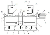
fig. 1 is a schematic view of the internal structure of the present invention;
fig. 2 is a schematic view of the top view of the internal structure of the present invention;
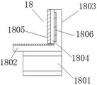
fig. 3 is a schematic structural diagram of the moving assembly of the present invention;
fig. 4 is a schematic view of the internal structure of the moving assembly of the present invention;
in the figure: the device comprises a collecting box-1, a bottom plate-2, a movable plate-3, an expansion link-4, a spring-5, a controller-6, an ejector rod-7, a bearing I-8, a protective cover-9, a groove-10, an inductor-11, a supporting plate-12, a motor-13, a bidirectional screw-14, a bearing II-15, a gear-16, a belt-17, a moving component-18, a supporting frame-19, an electric push rod-110, a pressing plate-111, a buffer layer-112, a box door-113, a sliding block-1801, a connecting plate-1802, a clamping plate-1803, a stress plate-1804, a friction layer-1805 and a pressure sensor-1806.
Detailed Description
In order to make the objects, technical solutions and advantages of the present invention more clearly understood, the present invention is further described in detail below with reference to the accompanying drawings and embodiments. It should be understood that the specific embodiments described herein are for purposes of illustration only and are not intended to limit the invention.
Referring to fig. 1, 2, 3 and 4, the present invention provides a workpiece fixing tool for a stamping die, including a collecting box 1, a controller 6 is disposed at a side end of the collecting box 1, two bidirectional screws 14 are disposed inside the collecting box 1, the side ends of the bidirectional screws 14 are connected to the collecting box 1 through two bearings 15, a gear 16 is disposed at one side of each bidirectional screw 14, the gears 16 are connected to each other through a belt 17, a supporting plate 12 is disposed at a side end of the collecting box 1, a motor 13 is disposed at an upper end of the supporting plate 12, an output end of the motor 13 is connected to one of the bidirectional screws 14, moving components 18 are symmetrically disposed inside the bidirectional screws 14, a push rod 7 is disposed at a middle portion of each bidirectional screw 14 and connected to the collecting box 1, a groove 10 is disposed at a top end of the collecting box 1, an inductor 11 is disposed inside the groove 10, the inductor 11 is used for inducing whether a workpiece is disposed at the upper end of the push rod 7, then the motor 13 is started to drive the bidirectional screws 14 to rotate through the gear 16 and the belt 17, therefore, the moving assembly 18 is driven to clamp the workpiece, and the problems that the efficiency is low and the working time is wasted due to the fact that most workpieces of the existing stamping die are manually fixed in the fixing aspect are solved;
the movable assembly 18 comprises a sliding block 1801 arranged at the bottom end and connected with the bidirectional screw 14, the upper end of the sliding block 1801 is connected with a connecting plate 1802, a clamping plate 1803 is arranged at the side end of the connecting plate 1802, the clamping plate 1803 is connected with a stress plate 1804 through a pressure sensor 1806, a friction layer 1805 is arranged at the outer end of the stress plate 1804, pressure is applied to the stress plate 1804 through a workpiece, the stress plate 1804 applies acting force to the pressure sensor 1806 through the pressure sensor 1806, the stress of the pressure sensor 1806 is started through a controller 6 control motor 13, and the problem that the workpiece is damaged due to the fact that the motor 13 drives the sliding block 1801 to rotate too much is avoided.
Wherein, 1 bottom of collecting box is equipped with bottom plate 2 through fly leaf 3, is equipped with telescopic link 4 and spring 5 between bottom plate 2 and the collecting box 1, sets up bottom plate 2 through the bottom at collecting box 1 to be connected with spring 5 through telescopic link 4, avoid the too big downward impact force of punching press in-process with this, lead to the device part to receive the vibration and cause the not permanent problem of life.
Wherein, 1 side of collecting box is equipped with the handle, makes things convenient for staff's drive arrangement to remove through the handle, avoids removing the problem of difficulty.
Wherein, collecting box 1 is inside to be slope form, and collecting box 1 is located the slope bottom and is equipped with chamber door 113, and the residue that produces in the stamping process falls into collecting box 1 bottom to slide to one under the effect on slope, later open chamber door 113 with the residue discharge can, solved present stamping process and appeared a large amount of residues easily, do not carry out effectual collection and lead to the problem of follow-up clearance difficulty.
The bottom end of the ejector rod 7 is connected with the collecting box 1 through a bearing I8, the bottom end of the ejector rod 7 is provided with a protective cover 9, and the ejector rod 7 is connected with the bearing I8, so that the ejector rod 7 can rotate, and a clamping stress point of a workpiece is conveniently adjusted.
Wherein, the top of the clamping plate 1803 is equipped with the support frame 19, the bottom of the support frame 19 is equipped with the electric putter 110, the output end of the electric putter 110 runs through the support frame 19 and is connected with the pressing plate 111, the bottom end of the pressing plate 111 is equipped with the buffer layer 112, the pressing plate 111 is pushed downwards through the ejector rod 7, so that the pressing plate 111 and the buffer layer 112 clamp the side end of the workpiece, and the workpiece is fixed more stably.
The buffer layer 112 and the friction layer 1805 are made of rubber materials, and the rubber materials have good flexibility, are not easy to wear, and have high friction force.
The buffer layer 112 and the friction layer 1805 are made of rubber materials, which are high-elasticity polymer materials with reversible deformation, and have elasticity at room temperature, and can generate large deformation under the action of small external force, and can recover the original shape after the external force is removed. Rubber is a completely amorphous polymer with a low glass transition temperature (Tg) and a molecular weight often very high, greater than several hundred thousand.
The rubber is divided into natural rubber and synthetic rubber. The natural rubber is prepared by extracting colloid from plants such as rubber tree and rubber grass and processing; synthetic rubbers are obtained by polymerization of various monomers. Rubber products are widely used in industry or in various aspects of life.
The working principle is as follows: the user firstly connects the controller 6, the inductor 11, the motor 13, the electric push rod 110 and the pressure sensor 1806 with an external power supply, then the workpiece is placed at the top end of the ejector rod 7, the workpiece starts the inductor 11 inside the groove 10, the inductor 11 starts the motor 13 to work through the controller 6, so that the motor 13 drives the bidirectional screw 14 to rotate through the gear 16 and the belt 17, the bidirectional screw 14 drives the slider 1801 to move mutually, the slider 1801 drives the clamping plate 1803 at the upper end of the connecting plate 1802 to clamp the workpiece, the workpiece applies pressure to the pressure sensor 1806 through the stress plate 1804, the pressure sensor 1806 controls the motor 13 to stop working through the controller 6, then the electric push rod 110 pushes the pressing plate 111 to compress the workpiece, and then punching work is performed, and thus the work is completed.
The foregoing shows and describes the general principles, essential features, and advantages of the invention. It should be understood by those skilled in the art that the present invention is not limited by the above embodiments, and the description in the above embodiments and the description is only preferred examples of the present invention, and is not intended to limit the present invention, and that the present invention can have various changes and modifications without departing from the spirit and scope of the present invention, and these changes and modifications all fall into the scope of the claimed invention. The scope of the invention is defined by the appended claims and equivalents thereof.
Claims (6)
1. A workpiece fixing tool for a stamping die is characterized by comprising a collecting box (1), a controller (6) is arranged at the side end of the collecting box (1), two bidirectional screws (14) are arranged in the collecting box (1), the side ends of the bidirectional screws (14) are connected with the collecting box (1) through a second bearing (15), gears (16) are arranged on one sides of the bidirectional screws (14), the gears (16) are connected through a belt (17), a supporting plate (12) is arranged at the side end of the collecting box (1), a motor (13) is arranged at the upper end of the supporting plate (12), the output end of the motor (13) is connected with one bidirectional screw (14), moving components (18) are symmetrically arranged in the bidirectional screws (14), an ejector rod (7) is arranged in the middle of the bidirectional screw (14) and connected with the collecting box (1), a groove (10) is arranged at the top end of the collecting box (1), an inductor (11) is arranged in the groove (10);
remove subassembly (18) including locating slider (1801) that the bottom is connected with two-way screw rod (14), slider (1801) upper end is passed through connecting plate (1802) and is connected, connecting plate (1802) side is equipped with clamping plate (1803), clamping plate (1803) are inside to be connected with atress board (1804) through pressure sensor (1806), atress board (1804) outer end is equipped with frictional layer (1805).
2. The workpiece fixing tool for the stamping die as claimed in claim 1, wherein: the bottom end of the collecting box (1) is provided with a bottom plate (2) through a movable plate (3), and a telescopic rod (4) and a spring (5) are arranged between the bottom plate (2) and the collecting box (1).
3. The workpiece fixing tool for the stamping die as claimed in claim 1, wherein: the side end of the collecting box (1) is provided with a handle.
4. The workpiece fixing tool for the stamping die as claimed in claim 1, wherein: the collecting box (1) is internally in a slope shape, and the collecting box (1) is arranged at the bottom end of the slope and is provided with a box door (113).
5. The workpiece fixing tool for the stamping die as claimed in claim 1, wherein: the bottom end of the ejector rod (7) is connected with the collecting box (1) through a bearing I (8), and a protective cover (9) is arranged at the bottom end of the ejector rod (7).
6. The workpiece fixing tool for the stamping die as claimed in claim 1, wherein: the clamp plate (1803) top is equipped with support frame (19), support frame (19) bottom is equipped with electric putter (110), electric putter (110) output runs through support frame (19) and is connected with clamp plate (111), clamp plate (111) bottom is equipped with buffer layer (112).
Priority Applications (1)
| Application Number | Priority Date | Filing Date | Title |
|---|---|---|---|
| CN202220168972.1U CN217166177U (en) | 2022-01-21 | 2022-01-21 | Workpiece fixing tool for stamping die |
Applications Claiming Priority (1)
| Application Number | Priority Date | Filing Date | Title |
|---|---|---|---|
| CN202220168972.1U CN217166177U (en) | 2022-01-21 | 2022-01-21 | Workpiece fixing tool for stamping die |
Publications (1)
| Publication Number | Publication Date |
|---|---|
| CN217166177U true CN217166177U (en) | 2022-08-12 |
Family
ID=82736247
Family Applications (1)
| Application Number | Title | Priority Date | Filing Date |
|---|---|---|---|
| CN202220168972.1U Active CN217166177U (en) | 2022-01-21 | 2022-01-21 | Workpiece fixing tool for stamping die |
Country Status (1)
| Country | Link |
|---|---|
| CN (1) | CN217166177U (en) |
-
2022
- 2022-01-21 CN CN202220168972.1U patent/CN217166177U/en active Active
Similar Documents
| Publication | Publication Date | Title |
|---|---|---|
| CN211191617U (en) | Automatic precision switching punching equipment | |
| CN214720796U (en) | Hydroelectric engineering panel drilling equipment | |
| CN217166177U (en) | Workpiece fixing tool for stamping die | |
| CN214161061U (en) | Punching machine for machining hardware plates | |
| CN111086261A (en) | Garbage collection briquetting device of mould processing usefulness | |
| CN214211996U (en) | Material grabbing mechanism of connecting line punching machine | |
| CN211990551U (en) | Make things convenient for stamping die of ejection of compact | |
| CN221581632U (en) | Sheet metal stamping device | |
| CN214235850U (en) | Waste material device that rises back is prevented in punching press of mechanical parts | |
| CN219053643U (en) | Novel anchor clamps with adjustable digit control machine tool is used | |
| CN220946836U (en) | Compression collecting equipment for recycling waste metals | |
| CN221790718U (en) | Stamping device is used in processing of old and useless steel | |
| CN218903502U (en) | Automatic off-line squeeze riveter | |
| CN213002336U (en) | Stamping device is used in processing of bottle-making machine accessory | |
| CN220611955U (en) | Sheet metal punching device | |
| CN216181171U (en) | Continuous punching device applied to large-table-board plastic uptake machine | |
| CN221022485U (en) | Quick powder forming machine | |
| CN221848343U (en) | Sheet metal part extrusion molding device | |
| CN221454041U (en) | Punching device for processing outer wheel die for medical treatment | |
| CN220296925U (en) | Clamp for plastic steel profile machining | |
| CN116060945B (en) | Combined type trimming die | |
| CN221064090U (en) | Punching equipment with collection mechanism | |
| CN218693014U (en) | Punching device convenient to centre gripping | |
| CN219402043U (en) | Surplus material collection device | |
| CN221493979U (en) | Precision spare and accessory part demolding stamping equipment |
Legal Events
| Date | Code | Title | Description |
|---|---|---|---|
| GR01 | Patent grant | ||
| GR01 | Patent grant |