CN217161386U - Quick assembly's two-sided data frame - Google Patents
Quick assembly's two-sided data frame Download PDFInfo
- Publication number
- CN217161386U CN217161386U CN202123327857.9U CN202123327857U CN217161386U CN 217161386 U CN217161386 U CN 217161386U CN 202123327857 U CN202123327857 U CN 202123327857U CN 217161386 U CN217161386 U CN 217161386U
- Authority
- CN
- China
- Prior art keywords
- vertical plate
- plate
- suspension
- shaped
- sides
- Prior art date
- Legal status (The legal status is an assumption and is not a legal conclusion. Google has not performed a legal analysis and makes no representation as to the accuracy of the status listed.)
- Active
Links
Images


Abstract
The utility model provides a fast assembly's two-sided data frame relates to and borrows data frame technical field, especially relates to a two-sided intelligent data frame for fast assembly, its characterized in that: the vertical plate is of a metal material hollow plate type structure, one side (inner side) of the vertical plate is provided with a longitudinal reinforcing rib and a transverse reinforcing rib, the longitudinal reinforcing rib is provided with a suspension rod fixing hole, and the transverse reinforcing rib is provided with a laminate fixing hole; t-shaped fixing legs are arranged on two sides of the suspension rod, and a U-shaped suspension groove and a wire passing hole are formed in the top of the suspension rod; the cross section of the laminated plate is L-shaped, the hanging hook is arranged at the top of the laminated plate, the fixing hole is formed in the outer side of the bottom of the laminated plate, the laminated plate is made of integrally formed metal or plastic materials, and therefore the laminated plate is convenient to install, disassemble, attractive and elegant, stable in structure and convenient to maintain and replace modern intelligent equipment.
Description
Technical Field
The utility model relates to a borrow data frame technical field, especially relate to a double-sided formula intelligence data frame for fast assembly.
Background
At present, the bookshelf in the library on the market is made of steel or wood. General multi-purpose steelframe of library, use the wooden frame for pleasing to the eye when opening the shelf and reading, select better timber for use more, the general front and back of considering capacity and convenience all is equipped with the display layer frame, and the library bookshelf adopts fixed connected mode in the current market mostly, but transport or can not dismantle when putting, lead to the cost of transportation height, books are accomodate and are put the limitation big, also have few library's bookshelf that can dismantle, but the weak point exists, first, the installation or dismantle complicacy, lead to the bookshelf the convenience relatively poor, second, poor stability, the bookshelf of most equipment has the condition of rocking from side to side or back and forth.
Such as: a bookshelf (publication No. CN 210383166U) convenient to assemble is spliced through the connection mode between a placing plate 9 and a first vertical plate 2 and a second vertical plate 7, and is a detachable connection mode, so that a user can conveniently disassemble and assemble the bookshelf, the user can place a book on the placing plate 9, when the user disassembles and assembles the bookshelf, the user can take out and insert the placing plate 9 by holding a side plate 4 with hands, the bookshelf is convenient to use, the connection mode between an X-shaped hurdle 1 and the first vertical plate 2 and the second vertical plate 7 is bolt fixing, and is a detachable connection mode, so the user can conveniently disassemble and assemble the bookshelf, and when the bookshelf is used, the X-shaped hurdle 1 can prevent the book from falling off the bookshelf; the bottom of first riser 2 and second riser 7 is pegged graft in pegging graft pipe 5, and pegging graft pipe 5 welds with backing plate 6, so can be convenient for the staff to assemble backing plate 6, first riser 2 and second riser 7, and backing plate 6 has increased the area of contact on first riser 2 and second riser 7 and ground, has strengthened the stability of bookshelf, but there is the phenomenon of left and right rocking between X hurdle 1 and first riser 2 and the second riser 7.
The library is installed on the bookshelf for improving the work and service efficiency, such as: modern intelligent equipment such as display screen, control box, camera, RFID read-write antenna.
Such as: the utility model provides a library borrows bookshelf by oneself (publication number CN 214548203U), the inside of bookshelf body is provided with the control box, the bottom of control box one side is installed and is swept a yard window, control panel is installed to the intermediate position of control box one side, one side that the control box is close to control panel is installed and is printed the export, the bottom of control box is installed and is placed the case, the inside of placing the case is provided with the chair, and the weak point is, and modern intelligent equipment maintains or changes inconveniently.
SUMMERY OF THE UTILITY MODEL
The utility model aims at solving the defects existing in the prior art and providing a quick-assembly double-sided data frame.
In order to achieve the above purpose, the utility model adopts the following technical scheme: the utility model provides a quick assembly's two-sided data frame, includes the riser, hangs pole, plywood, its characterized in that: the vertical plates are positioned on the left side and the right side of the material rack layer plate, the suspension rods are connected with the vertical plates on the left side and the right side, the top of the layer plate is hung on the suspension rods, and the bottom of the layer plate is fixed on the vertical plates on the left side and the right side;
the vertical plate is a hollow flat cylinder body composed of metal, the inner side surface of the vertical plate is provided with a longitudinal reinforcing rib and a plurality of transverse reinforcing ribs, the longitudinal reinforcing rib is provided with a suspension rod fixing hole, and the transverse reinforcing ribs are provided with laminate fixing holes;
fixing legs are arranged on two sides of the suspension rod, a U-shaped suspension groove is arranged in the middle section of the suspension rod, and a threading hole is formed in the bottom of the suspension groove;
the cross section of the laminated plate is L-shaped, the top of the laminated plate is provided with a sectional type suspension hook, and the suspension hook and a threading hole of the suspension groove are just in clearance so as not to cause structural interference; the outer sides of two sides of the bottom of the laminated plate are respectively provided with a fixing hole, and the laminated plate is made of integrally formed metal or plastic materials.
Preferably, the fixing feet on the two sides of the hanging rod are respectively installed on the hanging rod fixing holes of the vertical reinforcing ribs on the two sides of the vertical plate, the hanging hooks of the laminates on the two sides of the data frame are respectively hung on the two sides of the hanging groove in the middle section of the hanging rod, and the fixing holes in the bottoms of the laminates are fixed in the laminate fixing holes of the horizontal reinforcing ribs through screws.
Preferably, the longitudinal reinforcing ribs and the transverse reinforcing ribs form a structure shaped like a Chinese character feng, and the cross section of the hanging hook is U-shaped.
Preferably, the vertical plate is divided into an A-shaped vertical plate, a B-shaped vertical plate and a C-shaped vertical plate, the A-shaped vertical plate is used as an outer vertical plate of the data frame, and a single data frame and a plurality of data frames can be used when combined; the outer side edge of indulging of A2 riser is the arc angle design, and the lateral surface is equipped with multimedia intelligent equipment mounting groove, and the medial surface is equipped with multimedia intelligent equipment maintenance hole and detachable access hole apron, multimedia intelligent equipment mounting groove and multimedia intelligent equipment maintenance groove are through three-dimensional flat hollow structure intercommunication.
Preferably, two symmetrical laminates are hung on two sides of the hanging rod respectively, hanging hooks of the two laminates are buckled into a hanging groove in the middle section of the hanging rod together, and an intelligent equipment mounting space and a threading hole for connecting electric wires of the intelligent equipment mounting space are arranged between the two laminates.
Preferably, the top of the data rack is provided with a top plate, and the bottom of the data rack is provided with a bottom plate;
the bottom plate is fixed with the vertical plates on the two sides by screws.
Preferably, the roof upside is equipped with the control box mounting groove, and the roof top is equipped with the lamina tecti, has access hole and movable access panel on the lamina tecti, and the roof is equipped with the control box through wires hole with hang the pole through wires hole and correspond the position, and the roof is equipped with the roof with the top plywood couple of L type and hangs the groove, the roof hangs the groove and has hung the top plywood, the top plywood is opposite with other plywood couple directions.
Preferably, the type B vertical plate and the type A vertical plate are used as the outer vertical plate of the data frame, and the type A vertical plate and the type B vertical plate are used for a single data frame.
Preferably, both sides of the C-shaped vertical plate are provided with longitudinal reinforcing ribs and transverse reinforcing ribs, the data frames are combined and connected by adopting three vertical plate combinations of an A-shaped vertical plate, one or more C-shaped vertical plates and a B-shaped vertical plate, the C-shaped vertical plate is a middle connecting piece of the data frames, and a plurality of splicing extensions can be formed according to actual needs.
Compared with the prior art, the utility model has the advantages and positive effects that,
firstly, the method comprises the following steps: the installation is convenient, only the suspension rod needs to be fixed on the vertical plate, then the layer plate is hung in the suspension groove of the suspension rod, and finally the bottom of the layer plate is fixed on the vertical plate through screws, so that the installation can be completed through three simple steps.
Secondly, the method comprises the following steps: because the data frame is convenient to install, the data frame can be disassembled for transportation, the transportation cost is greatly reduced, and the damage risk in the transportation process is effectively reduced.
Thirdly, the method comprises the following steps: the shelf board is made of metal or plastic materials which are integrally formed, the shelf board is combined with the vertical board and then is the same as the triangular prism in reason, and the shelf boards are connected with the vertical board and are equal to a plurality of triangular prisms connected with the vertical board, so that the shelf board has good stability, and meanwhile, the T-shaped fixing foot is also beneficial to improving the problem of left-right swinging between the two vertical boards.
Fourth, pleasing to the eye, all can not see screw or hole at data frame four directions all around, smart machine's electric wire is all hidden at the back of two plywoods, and the top of data frame is installed to the control box, and the display screen embedding is in the riser, and whole data frame and modern smart machine such as display screen, control box, camera, RFID read-write antenna are all an organic whole, and the structure is in care of tightly and elegant appearance.
Fifth, modern smart machine's maintenance and change are convenient, and the riser opposite side is equipped with multi-media smart machine maintenance groove, convenient maintenance and change multi-media device, and the top of control box installation data frame is convenient for maintain and change the control box, and the plywood is dismantled simply, conveniently maintains and changes RFID reading and writing antenna and smart machine electric wire.
Sixth, easy extension, C type riser are the intermediate junction spare of a plurality of data frame combinations, can construct different reading spaces according to a plurality of concatenation extensions of actual need, enrich the inside design of putting of data venue, conveniently manage and improve books and accomodate and put the structure.
Drawings
Fig. 1 is a schematic structural view of the present invention;
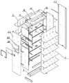
fig. 2 is an exploded schematic view of the present invention;
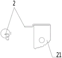
FIG. 3 is a schematic structural view of the suspension rod of the present invention;
FIG. 4 is a schematic side view of the suspension rod of the present invention;
FIG. 5 is a schematic side view of the laminate of the present invention;
fig. 6 is a schematic top view of the top plate of the present invention;
fig. 7 is a schematic bottom view of the top plate of the present invention;
fig. 8 is a schematic structural view of the a-shaped vertical plate of the present invention;
fig. 9 is a schematic structural view of the C-shaped vertical plate of the present invention;
FIG. 10 is a schematic view of a plurality of data rack assemblies of the present invention;
illustration of the drawings:
in the figure: 1. a vertical plate; 1-1, an A-type vertical plate; 1-2, a B-type vertical plate; 1-3, a C-shaped vertical plate 101 and a longitudinal reinforcing rib; 102. transverse reinforcing ribs; 103. A suspension rod fixing hole; 104. A laminate fixing hole; 105. multimedia intelligent equipment mounting grooves; 106. a multimedia intelligent equipment maintenance hole; 107. a manhole cover plate; 2. A suspension rod; 21. a fixing leg; 22. a suspension groove; 3. Laminating the plates; 31. a hanging hook; 32. a fixing hole; 4. A top plate; 41. a control box mounting groove; 42. a top cover plate; 43. an access hole; 44. a movable access panel; 45. a control box threading hole; 46. a top plate suspension groove; 5. A base plate.
Detailed Description
In order to make the above objects, features and advantages of the present invention more clearly understood, the present invention will be further described with reference to the accompanying drawings and examples. It should be noted that the embodiments and features of the embodiments of the present application may be combined with each other without conflict.
In the following description, numerous specific details are set forth in order to provide a thorough understanding of the present invention, however, the present invention may be practiced in other ways than those specifically described herein, and therefore the present invention is not limited to the limitations of the specific embodiments of the present disclosure.
the vertical plate 1 is a hollow flat cylinder made of metal, the inner side surface of the vertical plate 1 is provided with a longitudinal reinforcing rib 101 and a plurality of transverse reinforcing ribs 102, the longitudinal reinforcing rib 101 is provided with a suspension rod fixing hole 103, and the transverse reinforcing ribs 102 are provided with laminate fixing holes 104;
fixing feet 21 are arranged on two sides of the suspension rod 2, a U-shaped suspension groove 22 is arranged in the middle section of the suspension rod 2, and a threading hole is formed in the bottom of the suspension groove 22;
the cross section of the laminated plate 3 is L-shaped, the top of the laminated plate 3 is provided with a sectional type suspension hook 31, and the suspension hook 31 is just away from a threading hole of the suspension groove 22, so that structural interference cannot be caused; the outer sides of two sides of the bottom of the laminated plate 3 are respectively provided with a fixing hole 32, and the laminated plate 3 is made of integrally formed metal or plastic materials.
In embodiment 2, please refer to fig. 1-7, the fixing feet 21 on both sides of the hanging rod 2 are respectively installed on the hanging rod fixing holes 103 of the longitudinal reinforcing ribs 101 of the vertical plates 1 on both sides, so that the hanging rod 2 is connected with the vertical plates 1 on the left and right sides, the hanging hooks 31 of the two side plates 3 of the data shelf are respectively hung on both sides of the hanging groove 22 in the middle section of the hanging rod 2, so that the top of the plate 3 is hung on the hanging rod 2, the fixing holes 32 at the bottom of the plate 3 are fixed on the plate fixing holes 104 of the transverse reinforcing ribs 102 through screws, so that the bottom of the plate 3 is fixed on the vertical plates 1 on both sides.
T-shaped fixing feet 21 are arranged on two sides of the suspension rod 2, and a suspension groove 22 is arranged at the top of the suspension rod 2;
the cross section of the laminated plate 3 is L-shaped, the top of the laminated plate 3 is provided with a hanging hook 31, the cross section of the hanging hook 31 is inverted U-shaped, the outer side of the laminated plate 3 is provided with a fixing hole 32, and the laminated plate 3 is made of integrally formed metal or plastic materials.
The fixing feet on two sides of the hanging rod 2 are respectively arranged on the fixing holes of the hanging rods 2 of the vertical plates 1 on two sides, two symmetrical layer plates 3 are respectively hung in the front and the back of the hanging rod 2, the hanging hooks 31 of the two layer plates 3 are jointly buckled into the hanging grooves 22 on the top of the hanging rod 2, the two layer plates 3 are provided with intelligent equipment mounting spaces and threading holes for connecting electric wires of the intelligent equipment, and the fixing holes 32 at the bottom of the layer plates 3 are fixed on the layer plate fixing holes 104 of the transverse reinforcing ribs 102 through screws.
4 upsides of roof are equipped with control box mounting groove 41, and 4 tops of roof are equipped with roof plate 42, have access hole 43 and movable access panel 44 on the roof plate 42, and roof 4 is equipped with control box through wires hole 45 with the corresponding position of the 2 through wires holes that hang the pole, and roof 4 is equipped with roof suspension groove 46 with the 3 couples of plywood at L type top department that corresponds, and roof suspension groove 46 has hung the plywood 3 at top, and the plywood at top is with other plywood 3 couple opposite directions.
Example 4, referring to fig. 1-7, a single data rack is provided with two types of vertical plates, i.e., an a-type vertical plate 1-1 and a B-type vertical plate 1-2, the B-type vertical plate 1-2 and the a-type vertical plate 1-1 are used as the outer vertical plate of the data rack, and the suspension rod 2, the layer plate 3, the top plate 3 and the bottom plate 5 are installed in one or more combinations of the above examples 1-3.
The working principle is as follows:
the installation method only needs to fix the suspension rod on the vertical plate, then the layer plate is hung in the suspension groove of the suspension rod, finally the bottom of the layer plate is fixed on the vertical plate through screws, and the installation can be completed through three simple steps.
Because the data frame is convenient to install, the transportation can be disassembled, the transportation cost is greatly reduced, the design of the internal arrangement of the library is enriched, the book storage and placement structure is convenient to manage and improve
The plywood is the metal or the plastic material of integration shaping, just as the reason of triangular prism after combining with the riser, is equal to a plurality of triangular prisms and riser by a plurality of plywoods and riser connection, so has good stability, and the fixed foot of T shape also helps improving the problem of the side to side swaying between two risers simultaneously.
Screws or holes can not be seen in the data frame in all four directions, wires of the intelligent equipment are hidden on the back faces of the two laminates, the top of the data frame is installed on the control box, the display screen is embedded in the laminates, the whole data frame is integrated with modern intelligent equipment such as the display screen, the control box, the camera, the RFID read-write antenna and the like, and the structure is strict and attractive.
The foregoing is a preferred embodiment of the present invention, and not intended to limit the invention to other forms, which may be varied or modified by those skilled in the art based on the teachings herein, and which include: goods shelves, supporter, show cupboard etc. but all do not break away from the technical scheme content of the utility model, according to the technical essence of the utility model any simple modification, equivalent change and modification made to above embodiment still belong to the technical scheme's of the utility model protection scope.
Claims (9)
1. The utility model provides a quick assembly's two-sided data frame, including riser (1), suspension rod (2), plywood (3), its characterized in that: the vertical plates (1) are positioned at the left side and the right side of the material frame layer plate (3), the suspension rods (2) are connected with the vertical plates (1) at the left side and the right side, the top of the layer plate (3) is hung on the suspension rods (2), and the bottom of the layer plate (3) is fixed on the vertical plates (1) at the left side and the right side;
the vertical plate (1) is a hollow flat cylinder composed of metal, the inner side surface of the vertical plate (1) is provided with a longitudinal reinforcing rib (101) and a plurality of transverse reinforcing ribs (102), the longitudinal reinforcing rib (101) is provided with a suspension rod fixing hole (103), and the transverse reinforcing ribs (102) are provided with laminate fixing holes (104);
fixing feet (21) are arranged on two sides of the suspension rod (2), a U-shaped suspension groove (22) is arranged in the middle section of the suspension rod (2), and a threading hole is formed in the bottom of the suspension groove (22);
the cross section of the laminated plate (3) is L-shaped, a sectional type suspension hook (31) is arranged at the top of the laminated plate (3), and the suspension hook (31) is just in clearance with a threading hole of the suspension groove (22) so as not to cause structural interference; fixing holes (32) are respectively formed in the outer sides of two sides of the bottom of the laminated plate (3), and the laminated plate (3) is made of integrally formed metal or plastic materials.
2. The double-sided data rack of claim 1, wherein: the fixing feet (21) on two sides of the hanging rod (2) are respectively installed on the hanging rod fixing holes (103) of the longitudinal reinforcing ribs (101) of the vertical plates (1) on two sides, the hanging hooks (31) of the laminates (3) on two sides of the data frame are respectively hung on two sides of the hanging groove (22) in the middle section of the hanging rod (2), and the fixing holes (32) in the bottoms of the laminates (3) are fixed on the laminate fixing holes (104) of the transverse reinforcing ribs (102) through screws.
3. The double-sided data rack of claim 1, wherein: the longitudinal reinforcing ribs (101) and the transverse reinforcing ribs (102) form a 'feng' shaped structure, and the cross section of the hanging hook (31) is U-shaped.
4. The double-sided data rack of claim 1, wherein: the vertical plate (1) is divided into an A-shaped vertical plate (1-1), a B-shaped vertical plate (1-2) and a C-shaped vertical plate (1-3), the A-shaped vertical plate (1-1) is used as the vertical plate (1) on the outer side of the data frame, and a single data frame and a plurality of data frames can be used when combined; the vertical outer side edge of the A-type vertical plate (1-1) is designed to be an arc angle, the outer side surface of the A-type vertical plate is provided with a multimedia intelligent device mounting groove (105), the inner side surface of the A-type vertical plate is provided with a multimedia intelligent device maintenance hole (106) and a detachable access hole cover plate (107), and the multimedia intelligent device mounting groove (105) is communicated with the multimedia intelligent device maintenance groove through a three-dimensional flat hollow structure.
5. The double-sided data rack of claim 1, wherein: two symmetrical laminates (3) are hung on two sides of the hanging rod (2) respectively, hanging hooks (31) of the two laminates (3) are buckled into hanging grooves (22) in the middle section of the hanging rod (2) together, and an intelligent equipment mounting space and a threading hole for connecting electric wires of the intelligent equipment mounting space are arranged between the two laminates (3).
6. The double-sided data rack of claim 1, wherein: the top of the data rack is provided with a top plate (4), and the bottom of the data rack is provided with a bottom plate (5);
the bottom plate (5) is fixed with the vertical plates (1) on the two sides by screws.
7. A quick assemble, two-sided data rack according to claim 6, wherein: roof (4) upside is equipped with control box mounting groove (41), and roof (4) top is equipped with lamina tecti (42), has access hole (43) and movable access panel (44) on lamina tecti (42), and roof (4) correspond the position with suspension rod (2) through wires hole and are equipped with control box through wires hole (45), and lamina (3) couple department of corresponding at roof (4) and L type top is equipped with roof suspension groove (46), the lamina (3) that roof suspension groove (46) hung the top, the lamina and other lamina (3) couple opposite direction at top.
8. The double-sided data rack of claim 4, wherein: the B-type vertical plate (1-2) and the A-type vertical plate (1-1) are used as the outer vertical plate of the data frame, and the A-type vertical plate (1-1) and the B-type vertical plate (1-2) are used as the single data frame.
9. The double-sided data rack of claim 4, wherein: both sides of the C-shaped vertical plate (1-3) are provided with longitudinal reinforcing ribs (101) and transverse reinforcing ribs (102), the data frames are combined and connected by adopting three vertical plate combinations of an A-shaped vertical plate (1-1), one or more C-shaped vertical plates (1-3) and a B-shaped vertical plate (1-2), and the C-shaped vertical plate (1-3) is an intermediate connecting piece for combining the data frames and can be spliced and expanded according to actual needs.
Priority Applications (1)
| Application Number | Priority Date | Filing Date | Title |
|---|---|---|---|
| CN202123327857.9U CN217161386U (en) | 2021-12-28 | 2021-12-28 | Quick assembly's two-sided data frame |
Applications Claiming Priority (1)
| Application Number | Priority Date | Filing Date | Title |
|---|---|---|---|
| CN202123327857.9U CN217161386U (en) | 2021-12-28 | 2021-12-28 | Quick assembly's two-sided data frame |
Publications (1)
| Publication Number | Publication Date |
|---|---|
| CN217161386U true CN217161386U (en) | 2022-08-12 |
Family
ID=82732371
Family Applications (1)
| Application Number | Title | Priority Date | Filing Date |
|---|---|---|---|
| CN202123327857.9U Active CN217161386U (en) | 2021-12-28 | 2021-12-28 | Quick assembly's two-sided data frame |
Country Status (1)
| Country | Link |
|---|---|
| CN (1) | CN217161386U (en) |
-
2021
- 2021-12-28 CN CN202123327857.9U patent/CN217161386U/en active Active
Similar Documents
| Publication | Publication Date | Title |
|---|---|---|
| CN202445478U (en) | Assembled cabinet | |
| CN204410068U (en) | A kind of utility modules metal framework cabinet | |
| CN217161386U (en) | Quick assembly's two-sided data frame | |
| CN203302660U (en) | Easy-to-assemble and freely-combinable combined cabinet | |
| CN209965656U (en) | Storage cabinet | |
| CN212661565U (en) | Detachable hat and coat stand with mortise and tenon structure | |
| CN210471440U (en) | Side bearer and storage rack comprising same | |
| CN204734225U (en) | But fast assembly's exhibition frame | |
| CN201393727Y (en) | Hanging type convenient show shelf | |
| CN206390670U (en) | One kind is easy to assemble showing stand | |
| CN213308277U (en) | Clothes and hat cabinet flexible to assemble | |
| CN208708901U (en) | Composition file frame | |
| CN211961442U (en) | Assembled steel wood furniture structure | |
| CN203314570U (en) | Goods rack with base | |
| CN205568305U (en) | Four three -dimensional wardrobes | |
| CN208243304U (en) | Showcase built in rack | |
| US10045620B2 (en) | Reconfigurable furniture system | |
| CN210989159U (en) | A section bar structure for aluminum alloy frame | |
| CN217429715U (en) | Clothes hanger | |
| CN204393802U (en) | A kind of novel six layers of double-sided book shelves | |
| CN210300156U (en) | Junior middle school student manages storage rack with books | |
| CN203591039U (en) | Multifunctional outdoor occasional table | |
| CN109924698B (en) | Storage cabinet | |
| CN218852177U (en) | Heightening rack | |
| CN220631579U (en) | Concealed laminate support |
Legal Events
| Date | Code | Title | Description |
|---|---|---|---|
| GR01 | Patent grant | ||
| GR01 | Patent grant |