CN217140543U - Tea bag processing is with dust removal reducing mechanism - Google Patents
Tea bag processing is with dust removal reducing mechanism Download PDFInfo
- Publication number
- CN217140543U CN217140543U CN202220683783.8U CN202220683783U CN217140543U CN 217140543 U CN217140543 U CN 217140543U CN 202220683783 U CN202220683783 U CN 202220683783U CN 217140543 U CN217140543 U CN 217140543U
- Authority
- CN
- China
- Prior art keywords
- machine body
- dust
- area
- material cylinder
- crushing
- Prior art date
- Legal status (The legal status is an assumption and is not a legal conclusion. Google has not performed a legal analysis and makes no representation as to the accuracy of the status listed.)
- Active
Links
Images


Classifications
-
- Y—GENERAL TAGGING OF NEW TECHNOLOGICAL DEVELOPMENTS; GENERAL TAGGING OF CROSS-SECTIONAL TECHNOLOGIES SPANNING OVER SEVERAL SECTIONS OF THE IPC; TECHNICAL SUBJECTS COVERED BY FORMER USPC CROSS-REFERENCE ART COLLECTIONS [XRACs] AND DIGESTS
- Y02—TECHNOLOGIES OR APPLICATIONS FOR MITIGATION OR ADAPTATION AGAINST CLIMATE CHANGE
- Y02W—CLIMATE CHANGE MITIGATION TECHNOLOGIES RELATED TO WASTEWATER TREATMENT OR WASTE MANAGEMENT
- Y02W30/00—Technologies for solid waste management
- Y02W30/50—Reuse, recycling or recovery technologies
- Y02W30/62—Plastics recycling; Rubber recycling
Abstract
The utility model relates to the field of tea bag processing equipment, in particular to a dust removal and crushing device for tea bag processing, which comprises a crushing mechanism, a dust absorption mechanism and a dust absorption air pipe for connecting the crushing mechanism and the dust absorption mechanism; the crushing mechanism comprises a machine body, and a dust absorption area, a coarse crushing area, a fine crushing area and a collecting area are sequentially arranged in the machine body from top to bottom; a feeding hole is formed in the top of the machine body above the dust collection area; a first material cylinder is arranged in the dust absorption area, a stirring shaft is arranged in the first material cylinder, and stirring blades are arranged on the surface of the stirring shaft; the device can firstly carry out wind power dust collection on the raw materials, and the raw materials are stirred by the stirring shaft in the dust collection process, so that the dust far away from the dust collection port can be stirred and close to the dust collection port, and the dust collection efficiency is improved; then, the raw materials are coarsely crushed and finely crushed, and finally the obtained small-particle raw materials are stored in a collecting box; the whole process is convenient to operate and is beneficial to improving the working efficiency.
Description
Technical Field
The utility model relates to a tea bag processing equipment field especially relates to a tea bag processing is with dust removal reducing mechanism.
Background
The tea bag is made by wrapping tea leaves with paper or cloth, and can be stored for a long time and be flushed with water when in use; along with the trend of flower and fruit tea, the expansion of fruit grains and petals can not be accommodated in the common tea bag due to small space, and diamond tea bags begin to appear on the market. The diamond tea bag is just like a diamond in name, is in a regular tetrahedron structure, is packaged by food-grade nylon, is exquisite and transparent in appearance, has large space in the bag, and is beneficial to the emission of fragrance.
When making the tea bag, need earlier get rid of the tiny particle dust of adulteration in the tea raw materials such as flowers and fruits, then will drop into the rubbing crusher and smash into the tiny particle to make things convenient for follow-up bagging-off. However, at present, dust removal crushing equipment specially aiming at tea bag raw material treatment does not exist, dust removal in a dust remover is needed, then the dust removal crushing equipment is transported to a crusher to be crushed, the two pieces of equipment are carried out independently, and time and labor cost are increased.
SUMMERY OF THE UTILITY MODEL
In order to overcome the not enough of above-mentioned prior art, the utility model provides a tea bag processing is with dust removal reducing mechanism can accomplish the dust removal and the smashing of tea bag raw materials, and the simple operation improves work efficiency.
The utility model provides a technical scheme that its technical problem adopted is: a dust removal and smashing device for processing tea bags comprises a smashing mechanism, a dust absorption mechanism and a dust absorption air pipe for connecting the smashing mechanism and the dust absorption mechanism; the crushing mechanism comprises a machine body, and a dust absorption area, a coarse crushing area, a fine crushing area and a collecting area are sequentially arranged in the machine body from top to bottom; a feeding hole is formed in the top of the machine body above the dust collection area; a first material cylinder is arranged in the dust absorption area, an opening is formed in the top end of the first material cylinder, the bottom end of the first material cylinder is in a semi-cylindrical shape, a stirring shaft is arranged in the first material cylinder, stirring blades are arranged on the surface of the stirring shaft, one end of the stirring shaft is installed on a bearing on one side of the first material cylinder, and the other end of the stirring shaft is connected with an output shaft of a first motor located on the outer wall of the machine body; the first motor can drive the stirring shaft to rotate after being started, so that the stirring blade can stir the raw materials in the first material cylinder; a dust suction port is formed in one side of the first material cylinder, a first screen is installed at the dust suction port, and the dust suction port is connected with a dust suction mechanism through a dust suction air pipe located outside the machine body; when the raw materials in the first material cylinder are stirred, the dust on the surface enters the dust collection mechanism through the first screen and the dust collection air pipe; a barrel cover is mounted at the bottom of the first charging barrel through an electric control valve, and a worker can control the electric control valve from the outside to open the barrel cover so that the raw materials in the first charging barrel fall to a coarse crushing area; a plurality of rotary drums which are horizontally distributed are arranged in the coarse crushing area, crushing teeth are arranged on the surfaces of the rotary drums, and gaps are formed between the crushing teeth on the adjacent rotary drums; the left end and the right end of each rotary drum are provided with connecting plates which are fixedly arranged on the inner walls of the left side and the right side of the machine body, the left end and the right end of each rotary drum are arranged on bearings in the connecting plates, one end of each rotary drum is provided with a gear, adjacent rotary drums are connected through the meshing of the gears, and one end of one rotary drum is connected with an output shaft of a second motor positioned on the outer wall of the machine body; the second motor can drive one rotary drum connected with the second motor to rotate after being started, the rotary drum drives other rotary drums to rotate through gears, and the raw materials falling on the rotary drum fall to a fine crushing area from a gap after being coarsely crushed by the crushing teeth; a second material cylinder is arranged in the fine crushing area, an opening is formed in the top end of the second material cylinder, the bottom end of the second material cylinder is in a semi-cylindrical shape, a rotating shaft is arranged in the second material cylinder, a blade is arranged on the surface of the rotating shaft, one end of the rotating shaft is arranged on a bearing on one side of the second material cylinder, and the other end of the rotating shaft is connected with an output shaft of a third motor on one side of the second material cylinder; the third motor drives the rotating shaft to rotate after being started, so that the blade finely crushes the raw materials in the second material cylinder; the bottom end of the second material cylinder is provided with a second screen, and the finely-crushed raw materials fall into the collecting region through the second screen; and a collecting box is arranged in the collecting area.
The feed inlet is funnel-shaped with a wide upper part and a narrow lower part, and the raw materials to be treated are poured into the machine body from the upper part conveniently through the structure.
The collecting box is internally provided with an inclined plate, the horizontal plane of one end of the inclined plate close to the rear side of the machine body is higher than the horizontal plane of one end of the inclined plate close to the front side of the machine body, and the front side of the machine body is provided with a discharge hole at the position corresponding to the inclined plate; thus, the raw materials in the collecting box can slide out of the machine body through the inclined plate and the discharge hole; in order to improve the practicality, discharge gate department passes through automatically controlled valve connection baffle, can block the raw materials from the discharge gate roll-off when the baffle is closed.
The dust suction mechanism is preferably a bag type dust collector, and the structure and the principle of the dust suction mechanism belong to the prior art and are not described in detail.
The utility model has the advantages that: the dust removal and smashing device for processing the tea bags can firstly carry out wind power dust collection on raw materials, and the raw materials are stirred by the stirring shaft in the dust collection process, so that dust far away from a dust collection port can be stirred to be close to the dust collection port, and the dust collection efficiency is improved; then, the raw materials are coarsely crushed and finely crushed, and finally the obtained small-particle raw materials are stored in a collecting box; the whole process is convenient to operate and is beneficial to improving the working efficiency.
Drawings
In order to more clearly illustrate the embodiments of the present invention or the technical solutions in the prior art, the drawings needed to be used in the description of the embodiments or the prior art will be briefly described below, it is obvious that the drawings in the following description are only some embodiments of the present invention, and for those skilled in the art, other drawings can be obtained according to these drawings without inventive exercise.
FIG. 1 is a schematic structural view of the front side of the present invention;
FIG. 2 is a schematic view of the internal structure of the front side of the machine body;
FIG. 3 is a schematic diagram of the internal structure of the left side of the machine body;
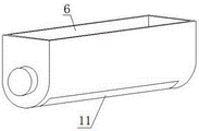
FIG. 4 is a schematic structural view of a first cartridge;
fig. 5 is a schematic diagram of the transmission of the drum.
The drawing shows that 1, a crushing mechanism, 2, a dust suction mechanism, 3, a dust suction air pipe, 4, a machine body, 5, a feed inlet, 6, a first material cylinder, 7, a stirring shaft, 8, a first motor, 9, a dust suction opening, 10, a first screen, 11, a cylinder cover, 12, a rotary cylinder, 13, a crushing tooth, 14, a connecting plate, 15, a gear, 16, a second motor, 17, a second material cylinder, 18, a rotating shaft, 19, a blade, 20, a third motor, 21, a second screen, 22, a collecting box, 23, an inclined plate, 24, a discharge opening and 25 are arranged.
Detailed Description
In order to make the objects, technical solutions and advantages of the present invention more apparent, the present invention is further described in detail with reference to the following embodiments. It should be understood that the specific embodiments described herein are for purposes of illustration only and are not intended to limit the invention.
Referring to fig. 1-5, the present embodiment provides a dust removal and pulverization device for processing tea bags, which includes a pulverization mechanism 1, a dust suction mechanism 2, and a dust suction air pipe 3 for connecting the pulverization mechanism 1 and the dust suction mechanism 2.
The crushing mechanism 1 comprises a machine body 4, and a dust absorption area, a coarse crushing area, a fine crushing area and a collecting area are sequentially arranged in the machine body 4 from top to bottom; a feed inlet 5 is formed in the top of the machine body 4 above the dust suction area, and the feed inlet 5 is of a funnel-shaped structure with a wide upper part and a narrow lower part; a first charging barrel 6 is installed in the dust absorption area through a bolt, an opening is formed in the top end of the first charging barrel 6, the bottom end of the first charging barrel is in a semi-cylindrical shape, a stirring shaft 7 which is horizontally arranged is arranged in the first charging barrel 6, stirring blades are arranged on the surface of the stirring shaft 7, one end of the stirring shaft 7 is installed on a bearing on one side of the first charging barrel 6, and the other end of the stirring shaft 7 is connected with an output shaft of a first motor 8 which is positioned on the outer wall of the machine body 4; the first motor 8 is arranged on the outer wall of the machine body 4 through a bolt; a dust suction port 9 is formed in the rear side wall of the first material cylinder 6, a detachable first screen 10 is installed at the dust suction port 9 through a clamping groove, the first screen 10 is arranged to prevent raw materials from being sucked, and the dust suction port 9 is connected with the dust suction mechanism 2 through a dust suction air pipe 3 located outside the machine body 4; the bottom of the first charging barrel 6 is provided with a barrel cover 11 through an electric control valve, and a worker can control the electric control valve from the outside to open the barrel cover 11, so that the dedusted raw materials in the first charging barrel 6 fall to a coarse crushing area.
A plurality of rotary drums 12 which are horizontally distributed are arranged in a coarse crushing area in the machine body 4, crushing teeth 13 for crushing raw materials are arranged on the surfaces of the rotary drums 12, gaps are arranged between the crushing teeth 13 on the adjacent rotary drums 12, and the crushed raw materials can fall from the gaps; both ends are equipped with the connecting plate 14 of bar structure about rotary drum 12, and bolt fixed mounting is on 4 left and right sides inner walls of organism for connecting plate 14, and install on the bearing in connecting plate 14 at rotary drum 12 left and right sides both ends, and rotary drum 12 one of them end fixed connection gear 15, and the gear 15 meshing on the adjacent rotary drum 12 is connected, and the output shaft that is located the second motor 16 of 4 outer walls of organism is connected to the one end of one of them rotary drum 12, and second motor 16 passes through the bolt and installs on organism 4.
A fine crushing area in the machine body 4 is provided with a second material cylinder 17, the second material cylinder 17 is connected to the inner wall of the machine body 4 through a bolt, the top end of the second material cylinder 17 is provided with an opening, the bottom end of the second material cylinder 17 is in a semi-cylindrical shape, a rotating shaft 18 which is horizontally arranged is arranged in the second material cylinder 17, a blade 19 is installed on the surface of the rotating shaft 18 through a screw, one end of the rotating shaft 18 is installed on a bearing at one side of the second material cylinder 17, and the other end of the rotating shaft 18 is connected with an output shaft of a third motor 20 which is positioned at one side of the second material cylinder 17; the bottom end of the second material cylinder 17 is provided with a second screen 21 through a clamping groove.
A collecting box 22 for receiving raw materials is arranged in the collecting area, an inclined plate 23 is arranged in the collecting box 22, the horizontal plane of one end, close to the rear side of the machine body 4, of the inclined plate 23 is higher than the horizontal plane of one end, close to the front side of the machine body 4, of the inclined plate 23, and a discharge hole 24 is formed in the position, corresponding to the inclined plate 23, of the front side of the machine body 4; thus, the raw materials in the collecting box 22 can slide out of the machine body 4 through the inclined plate 23 and the discharge port 24 and directly fall into a container below the discharge port 24, so that the subsequent transportation is facilitated; as a further optimization, a baffle 25 can be connected to the discharge port 24 through an electrically controlled valve, and when the baffle 25 is closed, the raw material can be blocked from sliding out of the discharge port 24.
The working principle of the device is as follows: pouring the tea bag raw material to be processed into the first material cylinder 6 from the feeding hole 5, starting the dust collection mechanism 2 to generate negative pressure, and sucking away dust on the surface of the raw material through the first screen 10 and the dust collection air pipe 3; meanwhile, the first motor 8 drives the stirring shaft 7 to rotate, and the stirring blades stir the raw materials to roll, so that the dust removal effect is improved; then open the cover 11 of first feed cylinder 6 bottom through the automatically controlled valve, the raw materials drops on rotary drum 12, and second motor 16 drives rotary drum 12 and rotates, and this in-process, garrulous tooth 13 carries out the coarse crushing cutting to the raw materials, and the raw materials after the coarse crushing falls in second feed cylinder 17 from the clearance, and third motor 20 drives pivot 18 and rotates, makes blade 19 carry out the cutting in small, broken bits to the raw materials, and the raw materials after the fine crushing passes through second screen cloth 21 and gets into in the collecting box 22, accomplishes dust removal and crushing process.
Of course, the above description is not limited to the above examples, and technical features of the present invention that are not described in the present application may be implemented by or using the prior art, and are not described herein again; the above embodiments and drawings are only used for illustrating the technical solutions of the present invention and are not intended to limit the present invention, and the present invention has been described in detail with reference to the preferred embodiments, and those skilled in the art should understand that changes, modifications, additions or substitutions made by those skilled in the art within the spirit of the present invention should also belong to the protection scope of the claims of the present invention.
Claims (4)
1. A dust removal and smashing device for processing tea bags comprises a smashing mechanism (1), a dust absorption mechanism (2) and a dust absorption air pipe (3) used for connecting the smashing mechanism (1) and the dust absorption mechanism (2); the method is characterized in that: the crushing mechanism (1) comprises a machine body (4), and a dust absorption area, a coarse crushing area, a fine crushing area and a collecting area are sequentially arranged in the machine body (4) from top to bottom; a feeding hole (5) is formed in the top of the machine body (4) above the dust suction area; a first charging barrel (6) is arranged in the dust absorption area, an opening is formed in the top end of the first charging barrel (6), the bottom end of the first charging barrel is in a semi-cylindrical shape, a stirring shaft (7) is arranged in the first charging barrel (6), stirring blades are arranged on the surface of the stirring shaft (7), one end of the stirring shaft (7) is installed on a bearing on one side of the first charging barrel (6), and the other end of the stirring shaft (7) is connected with an output shaft of a first motor (8) located on the outer wall of the machine body (4); a dust suction port (9) is formed in one side of the first material cylinder (6), a first screen (10) is installed at the dust suction port (9), and the dust suction port (9) is connected with the dust suction mechanism (2) through a dust suction air pipe (3) located outside the machine body (4); the bottom of the first material cylinder (6) is provided with a cylinder cover (11) through an electric control valve; a plurality of rotary drums (12) which are horizontally distributed are arranged in the coarse crushing area, crushing teeth (13) are arranged on the surfaces of the rotary drums (12), and gaps are arranged between the crushing teeth (13) on the adjacent rotary drums (12); the left end and the right end of each rotary drum (12) are provided with connecting plates (14), the connecting plates (14) are fixedly installed on the inner walls of the left side and the right side of the machine body (4), the left end and the right end of each rotary drum (12) are installed on bearings in the connecting plates (14), one end of each rotary drum (12) is provided with a gear (15), adjacent rotary drums (12) are meshed and connected through the gears (15), and one end of one rotary drum (12) is connected with an output shaft of a second motor (16) located on the outer wall of the machine body (4); a second material cylinder (17) is arranged in the fine crushing area, an opening is formed in the top end of the second material cylinder (17), the bottom end of the second material cylinder is semi-cylindrical, a rotating shaft (18) is arranged in the second material cylinder (17), a blade (19) is installed on the surface of the rotating shaft (18), one end of the rotating shaft (18) is installed on a bearing on one side of the second material cylinder (17), and the other end of the rotating shaft (18) is connected with an output shaft of a third motor (20) located on one side of the second material cylinder (17); the bottom end of the second material cylinder (17) is provided with a second screen (21), and a collecting box (22) is arranged in the collecting area.
2. The dust removal and pulverization device for processing tea bags according to claim 1, characterized in that: the feed inlet (5) is in a funnel shape with a wide upper part and a narrow lower part.
3. The dust removal and pulverization device for processing tea bags according to claim 1, characterized in that: the collecting box (22) is internally provided with an inclined plate (23), the horizontal plane of one end of the inclined plate (23) close to the rear side of the machine body (4) is higher than the horizontal plane of one end of the inclined plate close to the front side of the machine body (4), and the front side of the machine body (4) is provided with a discharge hole (24) at the corresponding position of the inclined plate (23).
4. The tea bag processing dust removal and pulverization device according to claim 3, characterized in that: the discharge port (24) is connected with a baffle (25) through an electric control valve.
Priority Applications (1)
| Application Number | Priority Date | Filing Date | Title |
|---|---|---|---|
| CN202220683783.8U CN217140543U (en) | 2022-03-28 | 2022-03-28 | Tea bag processing is with dust removal reducing mechanism |
Applications Claiming Priority (1)
| Application Number | Priority Date | Filing Date | Title |
|---|---|---|---|
| CN202220683783.8U CN217140543U (en) | 2022-03-28 | 2022-03-28 | Tea bag processing is with dust removal reducing mechanism |
Publications (1)
| Publication Number | Publication Date |
|---|---|
| CN217140543U true CN217140543U (en) | 2022-08-09 |
Family
ID=82697400
Family Applications (1)
| Application Number | Title | Priority Date | Filing Date |
|---|---|---|---|
| CN202220683783.8U Active CN217140543U (en) | 2022-03-28 | 2022-03-28 | Tea bag processing is with dust removal reducing mechanism |
Country Status (1)
| Country | Link |
|---|---|
| CN (1) | CN217140543U (en) |
-
2022
- 2022-03-28 CN CN202220683783.8U patent/CN217140543U/en active Active
Similar Documents
| Publication | Publication Date | Title |
|---|---|---|
| CN209753022U (en) | Chemical products processing is with smashing sieving mechanism | |
| CN211436361U (en) | Civil engineering construction waste treatment device | |
| CN210752901U (en) | Decorative board defective material retrieves reducing mechanism | |
| CN210496608U (en) | Breaker is used in processing of vegetable oil raw materials with filtering capability | |
| CN214346968U (en) | Traditional chinese medicine triturating device | |
| CN217140543U (en) | Tea bag processing is with dust removal reducing mechanism | |
| CN210131613U (en) | Feeding device is used in modified starch production | |
| CN207401579U (en) | A kind of building waste reducing mechanism | |
| CN211290732U (en) | Environment-friendly refuse treatment device for municipal works | |
| CN213913943U (en) | High-efficient pigment grinder | |
| CN211526453U (en) | Boiler waste residue pretreatment equipment | |
| CN211190469U (en) | Building material rubbing crusher | |
| CN211937241U (en) | Integrative crushing apparatus of first powder deironing of feed ingredient | |
| CN217962318U (en) | Hardware product research and development material processing equipment | |
| CN220634637U (en) | Efficient clear powder machine | |
| CN110918209A (en) | Food detects uses rubbing crusher | |
| CN217910794U (en) | Former material grinder of ji mushroom | |
| CN220258142U (en) | Chilli pulverizer with nose choking prevention function | |
| CN217725813U (en) | Crushing apparatus of raw materials for machine-made charcoal processing | |
| CN220386745U (en) | Pulverizer for industrial waste treatment | |
| CN219898465U (en) | Energy-saving white carbon black grinding treatment device | |
| CN220216183U (en) | Aluminum alloy waste briquetting machine | |
| CN219273153U (en) | Crushing and granulating machine | |
| CN216323336U (en) | A reducing mechanism for production of hickory chick drink | |
| CN211303380U (en) | Prevent rubbing crusher of waste material jam |
Legal Events
| Date | Code | Title | Description |
|---|---|---|---|
| GR01 | Patent grant | ||
| GR01 | Patent grant |