CN217121665U - Brake disc processing integral type mould - Google Patents
Brake disc processing integral type mould Download PDFInfo
- Publication number
- CN217121665U CN217121665U CN202220745632.0U CN202220745632U CN217121665U CN 217121665 U CN217121665 U CN 217121665U CN 202220745632 U CN202220745632 U CN 202220745632U CN 217121665 U CN217121665 U CN 217121665U
- Authority
- CN
- China
- Prior art keywords
- workbench
- brake disc
- plate
- workstation
- disc
- Prior art date
- Legal status (The legal status is an assumption and is not a legal conclusion. Google has not performed a legal analysis and makes no representation as to the accuracy of the status listed.)
- Active
Links
- 230000007246 mechanism Effects 0.000 claims abstract description 19
- 230000009194 climbing Effects 0.000 claims abstract description 4
- 238000004140 cleaning Methods 0.000 claims description 16
- 238000009434 installation Methods 0.000 claims description 16
- 238000003754 machining Methods 0.000 claims description 4
- 230000000149 penetrating effect Effects 0.000 claims description 3
- 238000010030 laminating Methods 0.000 claims 1
- 238000003825 pressing Methods 0.000 abstract description 3
- 238000000034 method Methods 0.000 description 2
- 239000002699 waste material Substances 0.000 description 2
- 241000220317 Rosa Species 0.000 description 1
- 230000008859 change Effects 0.000 description 1
- 238000010586 diagram Methods 0.000 description 1
- 230000006872 improvement Effects 0.000 description 1
- 238000004519 manufacturing process Methods 0.000 description 1
- 230000008569 process Effects 0.000 description 1
- 238000007493 shaping process Methods 0.000 description 1
- 238000006467 substitution reaction Methods 0.000 description 1
Images


Abstract
The utility model discloses a brake disc processing integral type mould belongs to brake disc mold processing technical field. The automatic lifting device comprises a workbench, wherein a mold cavity is formed in the center of the top of the workbench, a jacking mechanism is installed in the mold cavity, sliding grooves are formed in two sides of the top of the workbench, a collecting box is installed at the upper end of the front end of the workbench, a supporting frame is fixedly installed at the top of the workbench, an air cylinder is installed in the center of the top of the supporting frame, the output end of the air cylinder is connected with a telescopic rod, and a pressing disc is installed at the bottom of the telescopic rod; the utility model discloses a climbing mechanism who sets up can be automatically with fashioned brake disc from the die cavity in the liftout to the staff of being convenient for takes.
Description
Technical Field
The utility model relates to a brake disc mold processing technical field, more specifically say, relate to a brake disc processing integral type mould.
Background
The brake disc is in the in-process of production, presses the shaping through the mould usually, and the mould is when the process of using, and the brake disc blocks easily inside the mould, and the staff of being inconvenient for takes out fashioned brake disc from the mould, is unfavorable for the use.
Therefore, the brake disc machining integrated die is provided to solve the problems.
SUMMERY OF THE UTILITY MODEL
An object of the utility model is to provide a brake disc processing integral type mould can be automatically with fashioned brake disc from the die cavity in the liftout to the staff of being convenient for takes.
The purpose of the utility model can be realized by the following technical scheme:
the utility model provides a brake disc processing integral type mould, includes the workstation, workstation top center department has seted up the die cavity, install climbing mechanism in the die cavity, the spout has all been seted up to workstation top both sides, workstation front end upper end is installed and is collected the box, workstation top fixed mounting has the support frame, support frame top center department installs the cylinder, the cylinder output is connected with the telescopic link, the pressure dish is installed to the telescopic link bottom.
As a further aspect of the present invention: the jacking mechanism comprises a disc, a slide bar is fixedly mounted at the center of one end of the disc, one end, far away from the disc, of the slide bar penetrates through the workbench and is connected inside the workbench in a sliding mode, and a moving block is fixedly mounted at one end, penetrating through the workbench, of the slide bar.
As a further aspect of the present invention: the movable block is characterized in that a mounting column is fixedly mounted at the top of the movable block, a jacking plate is rotatably connected to the mounting column, and a connecting column is rotatably connected to one end, far away from the mounting column, of the jacking plate.
As a further aspect of the present invention: the utility model discloses a mould, including spliced pole, bottom plate, mounting piece, bottom plate sliding connection, spliced pole both ends all fixed mounting have the installation piece, fixed mounting has the bottom plate between the installation piece top, bottom plate sliding connection is in the mould intracavity.
As a further aspect of the present invention: the cleaning mechanism is installed at the top of the workbench and comprises a pulling plate, a movable plate is fixedly installed at the bottom of the pulling plate, a cleaning brush is installed at the bottom of the movable plate and is attached to the surface of the workbench, sliders are fixedly installed on two sides of the bottom of the movable plate, and the sliders are connected in the sliding grooves in a sliding mode.
As a further aspect of the present invention: the movable plate is characterized in that a fixed plate is fixedly mounted on one side of the movable plate, a bolt is connected to the fixed plate through threads, a knob is fixedly mounted at the top of the bolt, and the bolt is connected with a workbench through threads.
The utility model has the advantages that: after the brake disc processing of intracavity is accomplished, promote the disc, make the slide bar slide in to the workstation inside, it slides inside the workstation to drive the movable block, because the erection column is installed at the movable block top, it is connected with the jacking board to rotate on the erection column, it is connected with the spliced pole to rotate on the jacking board, so when the movable block slides, it moves to drive the jacking board through the erection column, it rises to drive the spliced pole, because the installation piece is all installed at the spliced pole both ends, the installation piece is all installed in the bottom plate bottom, bottom plate sliding connection is in the die cavity, so when the spliced pole rises, it rises to drive the bottom plate through the installation piece, make the bottom plate upwards slide from the die cavity in, thereby with the brake disc from ejecting in the die cavity, the utility model discloses a climbing mechanism who sets up, can be automatic with fashioned brake disc from ejecting in the die cavity, thereby the staff of being convenient for takes.
Drawings
In order to facilitate understanding for those skilled in the art, the present invention will be further described with reference to the accompanying drawings.
Fig. 1 is a schematic view of the overall structure of the present invention;
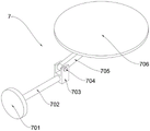
fig. 2 is a schematic structural view of the jacking mechanism of the present invention;
FIG. 3 is a schematic view of a partial structure of the present invention;
fig. 4 is a schematic structural diagram of the cleaning mechanism of the present invention.
The reference numbers in the figures illustrate: 1. a work table; 2. a mold cavity; 3. a support frame; 4. a cylinder; 5. a telescopic rod; 6. pressing the disc; 7. a jacking mechanism; 701. a disc; 702. a slide bar; 703. a moving block; 704. mounting a column; 705. a jacking plate; 706. a base plate; 707. connecting columns; 708. mounting blocks; 8. a collection box; 9. a cleaning mechanism; 901. pulling a plate; 902. moving the plate; 903. a slider; 904. cleaning a brush; 905. a fixing plate; 906. a knob; 907. a bolt; 10. a chute.
Detailed Description
The drawings in the embodiments of the present invention will be combined; the technical scheme in the embodiment of the utility model is clearly and completely described; obviously; the described embodiments are only some of the embodiments of the present invention; rather than all embodiments. Based on the embodiment of the utility model; all other embodiments obtained by a person skilled in the art without making any inventive step; all belong to the protection scope of the utility model.
Example (b):
as shown in fig. 1-3, the brake disc processing integrated die comprises a workbench 1, a die cavity 2 is formed in the center of the top of the workbench 1, a jacking mechanism 7 is installed in the die cavity 2, sliding grooves 10 are formed in two sides of the top of the workbench 1, a collecting box 8 is installed at the upper end of the front end of the workbench 1, a supporting frame 3 is fixedly installed at the top of the workbench 1, a cylinder 4 is installed at the center of the top of the supporting frame 3, an output end of the cylinder 4 is connected with a telescopic rod 5, and a pressing disc 6 is installed at the bottom of the telescopic rod 5;
the jacking mechanism 7 comprises a disc 701, a sliding rod 702 is fixedly installed at the center of one end of the disc 701, one end, far away from the disc 701, of the sliding rod 702 penetrates through the workbench 1 and is connected inside the workbench 1 in a sliding mode, a moving block 703 is fixedly installed at one end, penetrating through the workbench 1, of the sliding rod 702, and when the disc 701 is pushed, the sliding rod 702 can slide into the workbench 1, and the moving block 703 on the sliding rod 702 can slide inside the workbench 1;
the top of the moving block 703 is fixedly provided with an installation column 704, the installation column 704 is rotatably connected with a lifting plate 705, one end of the lifting plate 705, far away from the installation column 704, is rotatably connected with a connection column 707, and when the moving block 703 slides in the workbench 1, the installation column 704 arranged at the top can drive the lifting plate 705 to move, so that the connection column 707 rotatably connected with the lifting plate 705 ascends;
the equal fixed mounting in spliced pole 707 both ends has installation piece 708, fixed mounting has bottom plate 706 between the installation piece 708 top, bottom plate 706 sliding connection is in die cavity 2, and when spliced pole 707 rose, installation piece 708 through the both ends installation can drive bottom plate 706 and rise, makes bottom plate 706 follow the interior bottom of die cavity 2 upwards slide to can be with the finished product in the die cavity 2 follow die cavity 2 in the top, the staff of being convenient for takes.
The utility model discloses a theory of operation: after the brake disc in the mold cavity 2 is processed, the disc 701 is pushed, the sliding rod 702 slides into the workbench 1 to drive the moving block 703 to slide in the workbench 1, the mounting post 704 is mounted at the top of the moving block 703, the lifting plate 705 is rotatably connected to the mounting post 704, and the connecting post 707 is rotatably connected to the lifting plate 705, so that when the moving block 703 slides, the lifting plate 705 is driven by the mounting post 704 to move to drive the connecting post 707 to ascend, the mounting blocks 708 are mounted at both ends of the connecting post 707, the mounting blocks 708 are both mounted at the bottom of the bottom plate 706, and the bottom plate 706 is slidably connected in the mold cavity 2, so that when the connecting post 707 ascends, the bottom plate 706 is driven by the mounting block 708 to ascend, so that the bottom plate 706 slides upwards from the mold cavity 2, and the brake disc is ejected from the mold cavity 2, the lifting mechanism 7 can automatically eject the formed brake disc from the mold cavity 2, thereby being convenient for the staff to take.
As shown in fig. 4, a cleaning mechanism 9 is installed at the top of the workbench 1, the cleaning mechanism 9 includes a pulling plate 901, a moving plate 902 is fixedly installed at the bottom of the pulling plate 901, a cleaning brush 904 is installed at the bottom of the moving plate 902, the cleaning brush 904 is attached to the surface of the workbench 1, sliders 903 are fixedly installed at two sides of the bottom of the moving plate 902, the sliders 903 are slidably connected in the sliding grooves 10, a fixing plate 905 is fixedly installed at one side of the moving plate 902, a bolt 907 is connected to the fixing plate 905 in a threaded manner, a knob 906 is fixedly installed at the top of the bolt 907, and the bolt 907 is connected to the workbench 1 in a threaded manner.
The working principle is as follows: when the surface waste of the workbench 1 is excessive, the knob 906 is rotated to rotate the bolt 907, the bolt 907 slides out of the workbench 1, the pulling plate 901 is pulled to drive the moving plate 902 to move, and since the sliders 903 are mounted on two sides of the bottom of the moving plate 902 and are slidably connected in the sliding grooves 10, when the moving plate 902 moves, the moving plate 902 can move at the top of the workbench 1 through the sliding connection of the sliders 903 and the sliding grooves 10, and since the cleaning brush 904 is mounted at the bottom of the moving plate 902 and is attached to the surface of the workbench 1, when the moving plate 902 moves, the cleaning brush 904 can be driven to move, so that the cleaning brush 904 cleans the waste on the surface of the workbench 1.
The above; is only a preferred embodiment of the present invention; however, the scope of protection of the present invention is not limited thereto; any person skilled in the art is within the technical scope of the present disclosure; according to the technical scheme of the utility model and the improvement conception, equivalent substitution or change is carried out; are all covered by the protection scope of the utility model. Furthermore, the word "comprising" does not exclude other elements or steps, and the word "a" or "an" preceding an element does not exclude the presence of a plurality of such elements. Several elements of the plurality recited in the product claims may be implemented by one element in software or hardware. The terms first, second, etc. are used to denote names, but not any particular order.
Claims (6)
1. The utility model provides a brake disc processing integral type mould which characterized in that: including workstation (1), workstation (1) top center department has seted up die cavity (2), install climbing mechanism (7) in die cavity (2), spout (10) have all been seted up to workstation (1) top both sides, workstation (1) front end upper end is installed and is collected box (8), workstation (1) top fixed mounting has support frame (3), support frame (3) top center department installs cylinder (4), cylinder (4) output is connected with telescopic link (5), press disc (6) are installed to telescopic link (5) bottom.
2. The integrated die for machining the brake disc according to claim 1, wherein: the jacking mechanism (7) comprises a disc (701), a sliding rod (702) is fixedly mounted at the center of one end of the disc (701), one end, far away from the disc (701), of the sliding rod (702) penetrates through the workbench (1) and is connected inside the workbench (1) in a sliding mode, and a moving block (703) is fixedly mounted at one end, penetrating through the workbench (1), of the sliding rod (702).
3. The integrated die for processing the brake disc as claimed in claim 2, wherein: the top of the moving block (703) is fixedly provided with an installation column (704), the installation column (704) is connected with a jacking plate (705) in a rotating mode, and one end, far away from the installation column (704), of the jacking plate (705) is connected with a connecting column (707) in a rotating mode.
4. The integrated die for machining the brake disc according to claim 3, wherein: the two ends of the connecting column (707) are fixedly provided with mounting blocks (708), a bottom plate (706) is fixedly arranged between the tops of the mounting blocks (708), and the bottom plate (706) is connected in the die cavity (2) in a sliding mode.
5. The integrated die for processing the brake disc as claimed in claim 1, wherein: cleaning mechanism (9) is installed at workstation (1) top, cleaning mechanism (9) include arm-tie (901), arm-tie (901) bottom fixed mounting has movable plate (902), cleaning brush (904) is installed to movable plate (902) bottom, cleaning brush (904) and workstation (1) surface laminating mutually, the equal fixed mounting in movable plate (902) bottom both sides has slider (903), the equal sliding connection of slider (903) is in spout (10).
6. The integrated die for machining the brake disc according to claim 5, wherein: the movable plate (902) is characterized in that a fixed plate (905) is fixedly installed on one side of the movable plate (902), a bolt (907) is connected to the fixed plate (905) in a threaded mode, a knob (906) is fixedly installed at the top of the bolt (907), and the bolt (907) is connected with the workbench (1) in a threaded mode.
Priority Applications (1)
| Application Number | Priority Date | Filing Date | Title |
|---|---|---|---|
| CN202220745632.0U CN217121665U (en) | 2022-04-01 | 2022-04-01 | Brake disc processing integral type mould |
Applications Claiming Priority (1)
| Application Number | Priority Date | Filing Date | Title |
|---|---|---|---|
| CN202220745632.0U CN217121665U (en) | 2022-04-01 | 2022-04-01 | Brake disc processing integral type mould |
Publications (1)
| Publication Number | Publication Date |
|---|---|
| CN217121665U true CN217121665U (en) | 2022-08-05 |
Family
ID=82647207
Family Applications (1)
| Application Number | Title | Priority Date | Filing Date |
|---|---|---|---|
| CN202220745632.0U Active CN217121665U (en) | 2022-04-01 | 2022-04-01 | Brake disc processing integral type mould |
Country Status (1)
| Country | Link |
|---|---|
| CN (1) | CN217121665U (en) |
-
2022
- 2022-04-01 CN CN202220745632.0U patent/CN217121665U/en active Active
Similar Documents
| Publication | Publication Date | Title |
|---|---|---|
| CN215237383U (en) | Stamping die is used in stamping workpiece processing | |
| CN212664687U (en) | Stamping die based on demoulding component | |
| CN113351762A (en) | Aluminium foil cutlery box processing is with many check cutlery box stamping forming equipment | |
| CN217121665U (en) | Brake disc processing integral type mould | |
| CN217700897U (en) | Automobile card plate processing and forming die | |
| CN217070339U (en) | Stamping forming integration mould | |
| CN210333981U (en) | Multi-station stamping die for automobile covering parts | |
| CN212144210U (en) | Sub vehicle frame hypoplastron stamping die before car | |
| CN210702179U (en) | Electronic end cover autoloading stamping equipment | |
| CN113083982A (en) | Automatic ejection mechanism of punching machine for producing refrigerator underframe | |
| CN219443213U (en) | Cold stamping forming's heat dissipation stamping workpiece | |
| CN220497517U (en) | Automobile upright column mold with rapid demolding structure | |
| CN218053622U (en) | Hot press molding device for air filter screen | |
| CN211660830U (en) | Molding press is used in button processing | |
| CN220075457U (en) | Plastic mold for processing and forming electric connector | |
| CN210450525U (en) | Sieve plate processing equipment | |
| CN220698005U (en) | Hardware perforating stamping die | |
| CN217315446U (en) | Drawing die for stamping part of electric tool | |
| CN219276789U (en) | Powder pressing tool | |
| CN212525645U (en) | Stamping die for manufacturing fan | |
| CN218891041U (en) | Motor housing end cover stamping device | |
| CN219926910U (en) | Stamping and shaping equipment for plastic cup cover | |
| CN211660887U (en) | New energy automobile motor aluminum hull production mould | |
| CN220837419U (en) | Numerical control punch with high accuracy | |
| CN215392047U (en) | Machining die for producing riveting sheet |
Legal Events
| Date | Code | Title | Description |
|---|---|---|---|
| GR01 | Patent grant | ||
| GR01 | Patent grant | ||
| PE01 | Entry into force of the registration of the contract for pledge of patent right | ||
| PE01 | Entry into force of the registration of the contract for pledge of patent right |
Denomination of utility model: An integrated mold for processing brake discs Effective date of registration: 20231128 Granted publication date: 20220805 Pledgee: Shandong Longkou Rural Commercial Bank Co.,Ltd. Pledgor: Longkou Lihe Machinery Parts Co.,Ltd. Registration number: Y2023980068088 |