CN217115272U - Emergent power distribution box convenient to wiring - Google Patents
Emergent power distribution box convenient to wiring Download PDFInfo
- Publication number
- CN217115272U CN217115272U CN202220210382.0U CN202220210382U CN217115272U CN 217115272 U CN217115272 U CN 217115272U CN 202220210382 U CN202220210382 U CN 202220210382U CN 217115272 U CN217115272 U CN 217115272U
- Authority
- CN
- China
- Prior art keywords
- fixed block
- sliding connection
- block
- box
- groove
- Prior art date
- Legal status (The legal status is an assumption and is not a legal conclusion. Google has not performed a legal analysis and makes no representation as to the accuracy of the status listed.)
- Expired - Fee Related
Links
- 230000006835 compression Effects 0.000 claims abstract description 33
- 238000007906 compression Methods 0.000 claims abstract description 33
- 230000001737 promoting effect Effects 0.000 claims description 2
- 238000003825 pressing Methods 0.000 description 18
- 238000000034 method Methods 0.000 description 12
- 230000000694 effects Effects 0.000 description 4
- FGRBYDKOBBBPOI-UHFFFAOYSA-N 10,10-dioxo-2-[4-(N-phenylanilino)phenyl]thioxanthen-9-one Chemical compound O=C1c2ccccc2S(=O)(=O)c2ccc(cc12)-c1ccc(cc1)N(c1ccccc1)c1ccccc1 FGRBYDKOBBBPOI-UHFFFAOYSA-N 0.000 description 1
- 230000003139 buffering effect Effects 0.000 description 1
- 230000008878 coupling Effects 0.000 description 1
- 238000010168 coupling process Methods 0.000 description 1
- 238000005859 coupling reaction Methods 0.000 description 1
- 230000007547 defect Effects 0.000 description 1
- 238000009434 installation Methods 0.000 description 1
Images


Landscapes
- Patch Boards (AREA)
Abstract
The utility model relates to a power distribution box apparatus technical field, concretely relates to emergent power distribution box convenient to wiring, including placing the box, sliding connection has the fixed block in placing the box, both sides sliding connection has right trapezoid's catch block respectively in the fixed block, the inclined plane of box is placed for placing dorsad to the opposite face of two catch blocks, sliding connection has two and catch block one-to-one's compression leg in the fixed block, compression leg one end stretch into in the fixed block and with the inclined plane contact of catch block, the compression leg other end stretches out the fixed block, the fixed block both sides articulate respectively have with the catch block corresponding and the compression bar of V-arrangement, the mutually opposite end of two catch blocks rather than the compression bar side contact of corresponding side, the compression bar free end exceeds the fixed block. The problem that the existing power components are inconvenient to fix is effectively solved; the utility model discloses the staff only needs to press electric power components and parts downwards, just can make the compression bar compress tightly fixedly to electric power components and parts, has reduced staff's work load.
Description
Technical Field
The utility model relates to a power distribution box apparatus technical field, concretely relates to emergent power distribution box convenient to wiring.
Background
When the staff need be to the electric power components and parts in the motor block terminal wiring, often need utilize the bolt to fix electric power components and parts, at fixed in-process, the staff need aim at electric power components and parts and bolt interface, nevertheless at the in-process of aiming at, because electric power components and parts shelters from the bolt interface, therefore the staff is not convenient for utilize the bolt to fix electric power components and parts.
SUMMERY OF THE UTILITY MODEL
To the above-mentioned condition, for overcoming prior art's defect, the utility model aims at providing an emergent power distribution box convenient to wiring, the effectual current electric power components and parts of having solved problem not convenient for fix.
The utility model provides a technical scheme be, an emergent power distribution box convenient to wiring, including placing the box, sliding connection has the fixed block in placing the box, both sides sliding connection has right trapezoid's promotion piece respectively in the fixed block, the inclined plane of box is placed for placing dorsad to two opposite faces that promote the piece, there are two compression legs with promotion piece one-to-one in the fixed block through spring sliding connection, compression leg one end stretches into in the fixed block and contacts rather than the inclined plane that corresponds the promotion piece, the fixed block is stretched out to the compression leg other end, the fixed block both sides articulate respectively has the compression bar with promotion piece corresponding and V-arrangement, the back of the body end rather than the compression bar side contact of corresponding side of two promotion pieces, the compression bar free end exceeds the fixed block.
Preferably, set up the inclined groove of lower extreme orientation compression bar slope on the promotion piece, sliding connection has and promotes a vertically connecting rod in the fixed block, be equipped with the reference column that inserts the inclined groove on the connecting rod, sliding connection has the gag lever post that is located promotion piece one side and rather than parallel in the fixed block, set up the groove of stepping down with the inclined groove symmetry on the gag lever post, be equipped with on the connecting rod and insert the inslot that steps down and push away post 11, set up a plurality of and gag lever post one-to-one's limiting groove on placing the box inner wall, the gag lever post can insert the limiting groove.
Preferably, a plurality of springs are uniformly distributed in the placing box along the width direction of the placing box, and the free ends of the springs are connected with the fixing blocks.
Preferably, the fixed block is provided with a limit groove, the placing box is internally connected with a plurality of limit blocks capable of being inserted into the limit groove through springs, the upper end face of each limit block is an inclined face inclined towards the fixed block, and the limit blocks are connected with the placing box through springs.
Preferably, the placing box is internally connected with a T-shaped pressing plate in a sliding mode, the limiting block is provided with a fixing groove, and the pressing plate extends into the fixing groove and is connected with the fixing groove in a sliding mode.
Preferably, threaded holes are formed in four corners of the placing box.
The utility model has the advantages that:
the utility model has simple structure, convenient operation, novel conception and strong practicability, the staff can press and fix the electric power components by pressing the electric power components downwards, the workload of the staff is reduced, the working efficiency of the staff is improved, the setting of the fixed block is convenient for supporting and limiting the electric power components, the setting of the pressing rod is convenient for pressing and fixing the electric power components, the setting of the inclined groove is convenient for leading the connecting rod to move upwards synchronously when the pushing block moves outwards, the arrangement of the abdicating groove and the pushing post is convenient for leading the connecting rod to move upwards, the limiting rod can move inwards synchronously, the limiting rod and the limiting groove are arranged, the initial position of the fixed block is convenient to be positioned, the limiting groove and the limiting block are arranged, the fixed block is convenient to limit the fixed block in the process of moving downwards, the setting of clamp plate, fixed slot is just with removing the spacing to the fixed block, and the setting of screw hole is convenient for fix spacingly placing the box.
Drawings
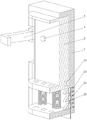
Fig. 1 is a schematic perspective view of the present invention;
FIG. 2 is a schematic view of the cut-away right-view three-dimensional structure of the present invention;
FIG. 3 is a schematic view of the front view of the cutting of the utility model;
FIG. 4 is a schematic view of the three-dimensional structure of the present invention with the fixing block removed;
fig. 5 is a schematic bottom perspective view of the present invention;
in the figure, 1-placing the box; 2, fixing blocks; 3-pushing the block; 4-pressing the column; 5-a pressing rod; 6-inclined groove; 7-a connecting rod; 8-a positioning column; 9-a limiting rod; 10-a abdication groove; 11-pushing the column; 12-a defined slot; 13-a limiting groove; 14-a limiting block; 15-pressing plate; 16-a fixed groove; 17-threaded hole.
Detailed Description
The following describes the embodiments of the present invention in further detail with reference to the accompanying drawings.
By figure 1 to 5 provide, an emergent power distribution box convenient to wiring, including placing box 1, place box 1 sliding connection has fixed block 2, it is equipped with a plurality of springs of its width direction equipartition along in the box 1 to place, the spring free end is connected with fixed block 2, under the effect of spring, there is the buffering fixed block 2 and place between the box 1, thereby make fixed block 2 at the in-process of lapse, the slow lapse of fixed block 2, avoided fixed block 2 and place the collision between the box 1, the service life of this device has been improved.
Both sides difference sliding connection has right trapezoid's promotion piece 3 in fixed block 2, two opposite faces that promote piece 3 are the inclined plane of placing box 1 dorsad, there are two compression leg 4 with promotion 3 one-to-one in the fixed block 2 through spring sliding connection, 4 one ends of compression leg stretch into in the fixed block 2 and with its inclined plane contact that corresponds promotion piece 3, the fixed block 2 is stretched out to the 4 other ends of compression leg, the inclined plane can make the in-process of compression leg 4 downstream, two promote 3 back movements of piece, thereby make and promote piece 3 and reach the assigned position, the spring can make 4 automatic initial position that resume of compression leg, the 4 other ends of compression leg stretch out behind fixed block 2, can make electrical apparatus oppress the one end that the compression leg 4 stretches out, thereby make this device reach the mesh that will realize.
2 both sides of fixed block articulate respectively have with the compressing rod 5 that promotes 3 corresponding and V-arrangement of piece, two carry on the back of the body end of promoting 3 and the 5 side contact of compressing rod that correspond the side rather than, 5 free ends of compressing rod exceed fixed block 2, compressing rod 5 can oppress electric power components and parts, compress tightly, thereby make fixing on fixed block 2 that electric power components and parts can be better, promote 3 and the contact of compressing rod 5, can make the in-process that promotes 3 outside removals of piece, two compressing rods 5 swing relatively.
Promote the inclined groove 6 of offering the lower extreme orientation compression bar 5 slope on the piece 3, sliding connection has and promotes 3 vertically connecting rod 7 of piece in the fixed block 2, be equipped with the reference column 8 that inserts in the inclined groove 6 on the connecting rod 7, at the in-process that promotes 3 outside movements of piece, inclined groove 6 outwards removes in step, because inclined groove 6 is to the 5 direction slopes of compression bar, so, connecting rod 7 upwards removes under the effect of reference column 8.
Sliding connection has the gag lever post 9 that is located promotion piece 3 one side and is rather than parallel in fixed block 2, offers on the gag lever post 9 with the groove of stepping down 10 of the 6 symmetries of inclined groove, be equipped with on connecting rod 7 and insert the support connotation 11 in the groove of stepping down 10, at the in-process that connecting rod 7 upwards moved, connecting rod 7 drives support connotation 11 and upwards moves, support connotation 11 drives gag lever post 9 and inwards moves under the effect of groove of stepping down 10
A plurality of limiting grooves 12 corresponding to the limiting rods 9 one by one are formed in the inner side wall of the placing box 1, the limiting rods 9 can be inserted into the limiting grooves 12, the limiting rods 9 move inwards and move out of the limiting grooves 12, and limiting of the initial positions of the fixing blocks 2 is removed.
The spacing groove 13 has been seted up on fixed block 2, it has a plurality of stopper 14 that can insert spacing groove 13 to place box 1 internal through spring coupling, stopper 14's up end is the inclined plane to 2 slopes of fixed block, stopper 14 is connected through the spring with placing box 1, at the in-process of 2 downstream of fixed block, fixed block 2 contacts with stopper 14's inclined plane, thereby oppress stopper 14 inclined plane, the compression of spring atress, when stopper 14 is corresponding with spacing groove 13, stopper 14 inserts spacing groove 13 under the spring action, thereby spacing fixed block 2.
Place the clamp plate 15 of box 1 sliding connection with T shape, seted up fixed slot 16 on the stopper 14, clamp plate 15 stretch into in the fixed slot 16 and with fixed slot 16 sliding connection, press down clamp plate 15, under the effect of fixed slot 16, clamp plate 15 oppresses stopper 14, the compression of spring atress to make stopper 14 break away from in the fixed slot 16, relieve the spacing to fixed block 2.
When the utility model is used, a worker firstly fixes the placing box 1 in the distribution box by using the bolt, and then fixes the distribution box in a proper position, and the work is ready at the moment;
when an operator needs to place an electric power component in the distribution box, the operator presses the electric power component backwards, the motor component is in contact with the compression leg 4, so that the compression leg 4 moves backwards, the compression leg 4 is in contact with the inclined surface of the pushing block 3 in the process of moving backwards of the compression leg 4, so that the two pushing blocks 3 move back to back, and the two pressing rods 5 swing oppositely while the two pushing blocks 3 move back to back, so that the pressing rods 5 press the electric power component;
when the two pushing blocks 3 move back to back, the connecting rod 7 moves upwards under the action of the inclined groove 6, and under the action of the abdicating groove 10, the two limiting rods 9 move relatively, so that the limiting rods 9 are separated from the limiting grooves 12, when the limiting rods 9 are separated from the limiting grooves 12, the two pressing rods 5 press the power components, and at the moment, the power components are fixed on the fixing block 2;
when the electric power component is fixed on the fixing block 2, a worker moves the fixing block 2 downwards, so that the electric wire can be better connected into the electric power component, the fixing block 2 presses the limiting block 14 in the downward movement process of the fixing block 2, the spring is stressed and compressed, the limiting block 14 is inserted into the limiting groove 13 under the action of the spring when the limiting groove 13 corresponds to the limiting block 14, so that the fixing block 2 is limited, when the fixing block 2 reaches a proper position, the worker stops pressing the fixing block 2 downwards, and at the moment, the fixing block 2 cannot move upwards under the action of the limiting block 14;
when the electric power components need to be replaced, a worker presses the pressing plate 15 backwards, the pressing plate 15 drives the limiting block 14 to move backwards, the spring is stressed and compressed, then the worker moves the fixing block 2 upwards to the limiting position, the two pressing rods 5 are pulled outwards at the moment, the compression on the electric power components is relieved, and meanwhile, the limiting rod 9 is inserted into the limiting groove 12 to limit the fixing block 2.
The utility model has simple structure, convenient operation, novel conception and strong practicability, the staff can press and fix the electric power components by pressing the electric power components downwards, the workload of the staff is reduced, the working efficiency of the staff is improved, the setting of the fixed block is convenient for supporting and limiting the electric power components, the setting of the pressing rod is convenient for pressing and fixing the electric power components, the setting of the inclined groove is convenient for leading the connecting rod to move upwards synchronously when the pushing block moves outwards, the arrangement of the abdicating groove and the pushing post is convenient for leading the connecting rod to move upwards, the limiting rod can move inwards synchronously, the limiting rod and the limiting groove are arranged, the initial position of the fixed block is convenient to be positioned, the limiting groove and the limiting block are arranged, the fixed block is convenient to limit the fixed block in the process of moving downwards, the setting of clamp plate, fixed slot is just with removing the spacing to the fixed block, and the setting of screw hole is convenient for fix spacingly placing the box.
Claims (6)
1. The utility model provides an emergent power distribution box convenient to wiring, is including placing box (1), its characterized in that: place box (1) sliding connection has fixed block (2), both sides difference sliding connection has right trapezoid's promotion piece (3) in fixed block (2), the inclined plane of two opposite faces that promote piece (3) for placing box (1) dorsad, there are two compression leg (4) with promotion piece (3) one-to-one in fixed block (2) through spring sliding connection, compression leg (4) one end stretches into in fixed block (2) and the inclined plane contact rather than corresponding promotion piece (3), compression leg (4) other end stretches out fixed block (2), fixed block (2) both sides articulate respectively have with the compressing tightly pole (5) of promoting piece (3) corresponding and V-arrangement, the end of carrying on the back of the body of two promotion pieces (3) contacts rather than compressing tightly pole (5) side of corresponding side, compressing tightly pole (5) free end exceeds fixed block (2).
2. An emergency power distribution box convenient to wire as defined in claim 1, wherein: set up down bevel groove (6) that the lower extreme orientation compressed bar (5) slope on promotion piece (3), sliding connection has and promotes piece (3) vertically connecting rod (7) in fixed block (2), be equipped with reference column (8) that insert in bevel groove (6) on connecting rod (7), sliding connection has the gag lever post (9) that is located promotion piece (3) one side and is rather than parallel in fixed block (2), set up groove (10) of stepping down with bevel groove (6) symmetry on gag lever post (9), be equipped with on connecting rod (7) and insert the post (11) that pushes away in groove (10), set up a plurality of and gag lever post (9) one-to-one's limiting groove (12) on placing box (1) inside wall, gag lever post (9) can insert in limiting groove (12).
3. An emergency power distribution box convenient to wire as defined in claim 1, wherein: a plurality of springs uniformly distributed along the width direction of the placing box (1) are arranged in the placing box, and the free ends of the springs are connected with the fixing blocks (2).
4. An emergency power distribution box convenient to wire as defined in claim 1, wherein: the limiting groove (13) is formed in the fixing block (2), a plurality of limiting blocks (14) capable of being inserted into the limiting groove (13) are connected into the placing box (1) through springs, the upper end faces of the limiting blocks (14) are inclined planes towards the fixing block (2), and the limiting blocks (14) are connected with the placing box (1) through springs.
5. An emergency power distribution box convenient to wire as defined in claim 1, wherein: place box (1) sliding connection has the clamp plate (15) of T shape, has seted up fixed slot (16) on stopper (14), clamp plate (15) stretch into in fixed slot (16) and with fixed slot (16) sliding connection.
6. An emergency power distribution box convenient to wire as defined in claim 1, wherein: threaded holes (17) are formed in four corners of the placing box (1).
Priority Applications (1)
| Application Number | Priority Date | Filing Date | Title |
|---|---|---|---|
| CN202220210382.0U CN217115272U (en) | 2022-01-26 | 2022-01-26 | Emergent power distribution box convenient to wiring |
Applications Claiming Priority (1)
| Application Number | Priority Date | Filing Date | Title |
|---|---|---|---|
| CN202220210382.0U CN217115272U (en) | 2022-01-26 | 2022-01-26 | Emergent power distribution box convenient to wiring |
Publications (1)
| Publication Number | Publication Date |
|---|---|
| CN217115272U true CN217115272U (en) | 2022-08-02 |
Family
ID=82597406
Family Applications (1)
| Application Number | Title | Priority Date | Filing Date |
|---|---|---|---|
| CN202220210382.0U Expired - Fee Related CN217115272U (en) | 2022-01-26 | 2022-01-26 | Emergent power distribution box convenient to wiring |
Country Status (1)
| Country | Link |
|---|---|
| CN (1) | CN217115272U (en) |
Cited By (1)
| Publication number | Priority date | Publication date | Assignee | Title |
|---|---|---|---|---|
| CN116799657A (en) * | 2023-08-24 | 2023-09-22 | 国网江苏省电力有限公司常州供电分公司 | Access type electric energy meter integrated fast-assembling support convenient to location |
-
2022
- 2022-01-26 CN CN202220210382.0U patent/CN217115272U/en not_active Expired - Fee Related
Cited By (2)
| Publication number | Priority date | Publication date | Assignee | Title |
|---|---|---|---|---|
| CN116799657A (en) * | 2023-08-24 | 2023-09-22 | 国网江苏省电力有限公司常州供电分公司 | Access type electric energy meter integrated fast-assembling support convenient to location |
| CN116799657B (en) * | 2023-08-24 | 2023-11-14 | 国网江苏省电力有限公司常州供电分公司 | Access type electric energy meter integrated fast-assembling support convenient to location |
Similar Documents
| Publication | Publication Date | Title |
|---|---|---|
| CN217115272U (en) | Emergent power distribution box convenient to wiring | |
| CN211088748U (en) | Electric intelligent equipment who facilitates use | |
| CN210147091U (en) | Edge cutting device with fixing mechanism for lithium battery production | |
| CN214866526U (en) | Fixed metal stamping die convenient to installation | |
| CN210547358U (en) | Punching device for metal electrical box | |
| CN211867533U (en) | Adjusting device and electricity core anchor clamps of baffle interval | |
| CN220190217U (en) | Push type climbing frame branch accuse case | |
| CN220639366U (en) | Concentrated laundry piece knurling molding device | |
| CN220401358U (en) | Winding displacement subassembly and intelligent high frequency switch DC power supply | |
| CN213043215U (en) | Processingequipment for patch cord | |
| CN217546549U (en) | Multilayer electrical equipment arrangement support | |
| CN216442693U (en) | Punching device is bound to agent's book keeping operation voucher | |
| CN213593615U (en) | Combined plastic suction mould | |
| CN212625397U (en) | Relay structure | |
| CN216355271U (en) | Porous rod-shaped terminal plug wire auxiliary device of group | |
| CN216355246U (en) | Terminal tightening device for high-low voltage wire harness | |
| CN216055884U (en) | Fixing device for electrical equipment | |
| CN220107744U (en) | New energy automobile motor structure convenient to dismouting maintenance | |
| CN213304709U (en) | Low-voltage distribution box clamp plate equipment mechanism | |
| CN213071013U (en) | Installation fixing device for relay | |
| CN219627330U (en) | 10KV cable locking and compacting equipment | |
| CN216154944U (en) | Separable iron sheet plug-in component taking tool | |
| CN210360462U (en) | Fixing device is used in machine part processing | |
| CN213212633U (en) | Mould is used in socket production convenient to dismantle | |
| CN215149795U (en) | Plug antenna piece cutting device |
Legal Events
| Date | Code | Title | Description |
|---|---|---|---|
| GR01 | Patent grant | ||
| GR01 | Patent grant | ||
| CF01 | Termination of patent right due to non-payment of annual fee | ||
| CF01 | Termination of patent right due to non-payment of annual fee |
Granted publication date: 20220802 |