CN217108202U - Oil seal - Google Patents
Oil seal Download PDFInfo
- Publication number
- CN217108202U CN217108202U CN202220717116.7U CN202220717116U CN217108202U CN 217108202 U CN217108202 U CN 217108202U CN 202220717116 U CN202220717116 U CN 202220717116U CN 217108202 U CN217108202 U CN 217108202U
- Authority
- CN
- China
- Prior art keywords
- seal
- sealing
- lip
- oil
- segment
- Prior art date
- Legal status (The legal status is an assumption and is not a legal conclusion. Google has not performed a legal analysis and makes no representation as to the accuracy of the status listed.)
- Active
Links
Images


Landscapes
- Sealing With Elastic Sealing Lips (AREA)
Abstract
The utility model discloses an oil seal, including the oil blanket body, the radial outside of oil blanket body is equipped with annular external seal circle, the radial inboard of oil blanket body is equipped with annular seal segment, be equipped with the linkage segment between seal segment and the external seal circle, the linkage segment is located the upper end of external seal circle, the internal surface of seal segment is the inside extension from top to bottom towards arc surface and seal segment, and the seal segment bottom is equipped with the seal lip, the seal lip has certain thickness and seal lip internal surface and is equipped with the seal lip mouth, be equipped with annular sealed skeleton in the seal lip, the seal lip is less than the bottom of external seal circle. The utility model has the advantages of simple structure, easy to assemble, guarantee the leakproofness after the sprayer installation, avoid the seepage.
Description
Technical Field
The utility model relates to an oil blanket technical field, concretely relates to oil blanket.
Background
After a plurality of oil sprayers are assembled on the cylinder cover, the problem that the coaxiality of the oil sprayers and the oil sprayer mounting holes on the cylinder cover is overlarge exists. The existing oil seal is sealed by the spring only through the assistance of the rubber lip, the rubber lip is soft, the primary lip is large in one-time compression amount and small in one-time compression amount, and the small side of the compression amount is easy to leak along with the attenuation of the holding force of the spring.
SUMMERY OF THE UTILITY MODEL
An object of the utility model is to provide an oil blanket guarantees the leakproofness of oil blanket to the sprayer when sprayer and sprayer mounting hole axiality are too big.
In order to achieve the above object, the utility model discloses an oil blanket body, its structural feature is: the radial outside of oil blanket body is equipped with annular external seal circle, the radial inboard of oil blanket body is equipped with annular seal segment, be equipped with the linkage segment between seal segment and the external seal circle, the linkage segment is located the upper end of external seal circle, the internal surface of seal segment is the arcwall face and the seal segment extends towards inside from top to bottom, and the seal segment bottom is equipped with the seal lip, the seal lip has certain thickness and the seal lip internal surface is equipped with the seal lip mouth, be equipped with annular sealed skeleton in the seal lip, the seal lip is less than the bottom of external seal circle.
After the structure is adopted, the outer surface of the outer sealing ring at the radial outer side of the oil seal is abutted on the cylinder cover, the outer edge of the outer sealing ring is abutted on the position of the fixed oil seal on the cylinder cover, the sealing section arranged at the radial inner side of the oil seal is provided with the sealing lip capable of sealing the oil injector, a connecting section is arranged between the outer sealing ring and the sealing section, the sealing section at the inner side is connected through the connecting section, the relative position of the sealing lip and the outer sealing ring is determined, the sealing lip at the bottom end of the sealing section is attached to the oil injector through the sealing lip, the sealing lip and the oil injector form surface sealing, the surface sealing is stronger than line sealing, a compression space is formed between the sealing section and the outer sealing ring, when the oil seal is installed, the sealing section bends and deforms towards the compression space, the sealing section of the oil seal is conveniently sleeved on the oil injector, an annular sealing framework is arranged in the sealing lip, after the oil injector is inserted into the installation hole of the cylinder cover, the oil sprayer is surrounded to the seal skeleton, guarantees that the seal lip surrounds the compressive capacity of oil sprayer everywhere and equals, and when the axiality that the oil sprayer inserted the cylinder head cover was great, the linkage segment of oil blanket takes place the bending, and annular seal skeleton still guarantees that the compressive capacity of seal lip equals, avoids the little sealed inefficacy that leads to of compressive capacity, the seepage scheduling problem appears.
The thickness of the sealing lip is larger than that of the upper end of the sealing section. The great convenience of thickness of seal lip holds sealed skeleton, has guaranteed the stability when sealed simultaneously, has guaranteed the leakproofness of oil blanket, and the less convenient bending of seal section upper end thickness, the seal section bending deformation when the seal section convenient installation after the bending, easy to assemble improves the installation effectiveness.
The cross section of the sealing framework is vertically arranged in the rectangular section and the rectangular section, the annular sealing framework is located inside the sealing lip, the stability of the sealing lip is guaranteed, meanwhile, the cross section of the sealing framework is vertically arranged in the rectangular section, the upper portion and the lower portion of the sealing framework are guaranteed to be supported for the sealing lip in the same mode, the compression amount of the sealing lip in the vertical height is equal, the face sealing of the sealing lip is guaranteed, and the sealing performance is improved.
An annular outer framework is arranged in the outer sealing ring, the outer framework plays a supporting role for the whole oil seal, the serious deformation of the oil seal in a mounting and oil sprayer working chamber is avoided, and the sealing of the oil seal on the oil sprayer is ensured.
The outer contour shape of the cross section of the outer framework is inverted L-shaped, one end of the outer framework extends into the connecting section, the strength and the shape of the connecting section are guaranteed, the connecting section is prevented from being bent frequently when the sealing section is bent, the strength of the connecting section is guaranteed, and the service life is prolonged.
The seal segment upside is equipped with the dust lip, the internal surface of dust lip is higher than the external seal circle for arcwall face and dust lip, and the upper end of dust lip supports between the gap between sprayer and mounting hole, avoids the dust to get into the cylinder head cover in, has guaranteed inside cleanness.
The oil seal body is integrally formed, the stability of the oil seal during use is improved due to the integrally formed design, and the service life is prolonged.
The framework materials of the sealing framework and the outer framework are metal or hard plastic, so that the supporting property of the framework is ensured, the production and the installation are convenient, and the economic benefit is improved.
To sum up, the utility model has the advantages of simple structure, easy to assemble, guarantee the leakproofness after the sprayer installation, avoid the seepage.
Drawings
The following detailed description of embodiments of the present invention is provided with reference to the accompanying drawings:
fig. 1 is a schematic cross-sectional structure of the present invention;
FIG. 2 is a schematic structural view of the utility model after installation;
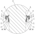
fig. 3 is an enlarged view of region a in fig. 2.
Detailed Description
Referring to fig. 1, the oil seal comprises an oil seal body, the oil seal body comprises an outer sealing ring 1 located on the radial outer side and a sealing section 3 located on the radial inner side of the oil seal, the outer sealing ring 1 and the sealing section 3 are both annular, a sealing lip 4 is arranged at the lower end of the annular sealing section 3, and a sealing lip opening 41 in the sealing lip 4 surrounds and presses the outer surface of the oil injector 8 to seal the oil injector 8. The outer seal ring 1 is abutted against the cylinder head cover 7, and an oil seal is arranged inside the cylinder head cover 7. The inner side of the outer sealing ring 1 is provided with a connecting section 2, the radial inner side of the connecting section 2 extends downwards to be provided with a sealing section 3, the bottom end of the sealing section 3 is provided with a sealing lip 4 which is abutted against the oil sprayer 8, and the sealing lip 4 is abutted against the outer surface of the oil sprayer 8. An outer framework 11 is arranged in the outer sealing ring 1, the outer framework 11 supports the outer contour and the whole oil seal, deformation of the oil seal is avoided, and the sealing reliability of the sealing lip 4 is improved. The outer framework 11 can be made of metal or hard materials, plays a role in supporting the outline of the whole oil seal, avoids the deformation of the outer sealing ring 1, and ensures the sealing performance of the oil seal. In this embodiment, the cross section of the outer frame 11 is in an inverted L shape, the L-shaped outer frame 11 extends into the connecting section 2, the strength of the connecting section 2 is enhanced, when the sealing section 3 deforms and extrudes the connecting section 2, the connecting section 2 is prevented from being broken, and the service life and the safety of the oil seal are enhanced. In other embodiments, the outer sealing ring 1 and the connecting section 2 can be respectively provided with a framework, so that the sealing performance and the strength of the outer ring of the oil seal are ensured. The inner side face of the sealing section 3 is arc-shaped, the lower end of the inner side face of the sealing section 3 is provided with a sealing lip 41 which abuts against the fuel injector 8, the sealing lip 41 surrounds the fuel injector 8, and the fuel injector 8 is sealed through the sealing lip 41. The sealing lip 41 is closer to the inner side than the inner surface of the sealing section 3, a sealing framework 42 is arranged in the sealing lip 4, the outer edge of the cross section of the sealing framework 42 is rectangular, the sealing framework 42 is vulcanized on the rear side of the sealing lip 41, the cross section of the sealing framework 42 is rectangular, and the height of the rectangular cross section is consistent with that of the sealing lip 41. When the oil seal is sleeved on the oil injector 8, the sealing framework 42 surrounds the oil injector 8, the sealing framework 42 supports the sealing lip 4, the sealing lip mouth 41 is compressed and attached to and extrudes the oil injector 8, and meanwhile, the sealing lip 4 is in surface sealing, so that the sealing performance of the sealing lip 4 is ensured. When the fuel injector 8 is installed through the installation hole of the cylinder head cover 7, the axis difference between the fuel injector 8 and the installation hole is large, the sealing framework 42 surrounds the fuel injector 8, the sealing section 3 deforms and distorts, but the distance between the sealing framework 42 and the fuel injector 8 is unchanged, so that the compression amount of the sealing lip 41 is unchanged, and the sealing of the sealing lip 41 to the fuel injector 8 is ensured. Through the sealing framework 42, the situation that the side, with different compression amount and small compression amount, of the sealing lip 41 is easy to leak and affect the sealing performance of the oil seal due to the fact that the coaxiality of the oil injector 8 and the mounting hole is different greatly is avoided. Meanwhile, the sealing lip 41 and the fuel injector 8 are in surface sealing, and the surface sealing ensures the contact area and the sealing performance of sealing, so that the sealing is more tight. The upper end of seal segment 3 is equipped with dust lip 5, and the up end of dust lip 5 is higher than the up end of external seal circle 1, and the internal surface of dust lip 5 is the arcwall face, and the lip of dust lip 5 supports on the space of sprayer 8 and mounting hole, and the arcwall face of internal surface makes things convenient for dust lip 5 to outwards warp, and then makes the lip laminating sprayer 8 surface of dust lip 5, avoids in the dust gets into cylinder head cover 7, has guaranteed inside cleanness. In this embodiment, oil blanket body integrated into one piece, integrated into one piece's design has increased the stability when the oil blanket uses, has improved life.
Referring to fig. 1 to 3, the oil seal is installed to seal the oil injector 8, the oil seal is first installed in the cylinder head cover 7, the outer surface of the outer sealing ring 1 of the oil seal body abuts against the cylinder head cover 7, and the shape of the oil seal is supported by the outer frame in the outer sealing ring 1. The fuel injector 8 penetrates through a mounting hole of the cylinder head cover 7 to be mounted, the fuel injector 8 penetrates through the sealing lip 4 of the oil seal, the sealing lip 41 of the sealing lip 4 wraps and extrudes the outer edge of the fuel injector 8, the sealing framework 42 of the sealing lip 4 surrounds the outer edge of the fuel injector 8, the sealing lip 41 of the sealing lip 4 is extruded, the sealing lip 41 is compressed, and the sealing performance is improved. When the coaxiality of the fuel injector 8 and the mounting hole of the cylinder head cover 7 is large, the sealing section 3 bends, and the sealing framework 42 keeps the compression amount of the surrounding sealing lip 41, so that the sealing performance of the oil seal is ensured.
Claims (8)
1. The utility model provides an oil blanket, includes the oil blanket body, characterized by: the radial outside of oil blanket body is equipped with annular outer seal ring (1), the radial inboard of oil blanket body is equipped with annular seal segment (3), be equipped with linkage segment (2) between seal segment (3) and outer seal ring (1), linkage segment (2) are located the upper end of outer seal ring (1), the internal surface of seal segment (3) is the arcwall face and seal segment (3) from top to bottom inside extension, and seal segment (3) bottom is equipped with seal lip (4), seal lip (4) have certain thickness and seal lip (4) internal surface and are equipped with seal lip mouth (41), be equipped with annular seal skeleton (42) in seal lip (4), seal lip (4) are less than the bottom of outer seal ring (1).
2. An oil seal as defined in claim 1, wherein: the thickness of the sealing lip (4) is larger than that of the upper end of the sealing section (3).
3. An oil seal as defined in claim 1, wherein: the cross section of the sealing framework (42) is a rectangular section and the rectangular section is vertically arranged.
4. An oil seal as defined in claim 1, wherein: an annular outer framework (11) is arranged in the outer sealing ring (1).
5. An oil seal as defined in claim 4, wherein: the outer contour shape of the cross section of the outer framework (11) is in an inverted L shape, and one end of the outer framework (11) extends into the connecting section (2).
6. An oil seal as defined in claim 1, wherein: the sealing section (3) upside is equipped with dust lip (5), the internal surface of dust lip (5) is higher than outer seal ring (1) for arcwall face and dust lip (5).
7. An oil seal as defined in claim 1, wherein: the oil seal body is integrally formed.
8. An oil seal as defined in claim 4, wherein: the framework materials of the sealing framework (42) and the outer framework (11) are metal or hard plastic.
Priority Applications (1)
| Application Number | Priority Date | Filing Date | Title |
|---|---|---|---|
| CN202220717116.7U CN217108202U (en) | 2022-03-30 | 2022-03-30 | Oil seal |
Applications Claiming Priority (1)
| Application Number | Priority Date | Filing Date | Title |
|---|---|---|---|
| CN202220717116.7U CN217108202U (en) | 2022-03-30 | 2022-03-30 | Oil seal |
Publications (1)
| Publication Number | Publication Date |
|---|---|
| CN217108202U true CN217108202U (en) | 2022-08-02 |
Family
ID=82578403
Family Applications (1)
| Application Number | Title | Priority Date | Filing Date |
|---|---|---|---|
| CN202220717116.7U Active CN217108202U (en) | 2022-03-30 | 2022-03-30 | Oil seal |
Country Status (1)
| Country | Link |
|---|---|
| CN (1) | CN217108202U (en) |
-
2022
- 2022-03-30 CN CN202220717116.7U patent/CN217108202U/en active Active
Similar Documents
| Publication | Publication Date | Title |
|---|---|---|
| CN217108202U (en) | Oil seal | |
| CN210000116U (en) | dustproof automobile fuel tank cover | |
| CN210196770U (en) | Novel pipe cap head | |
| CN216519354U (en) | Air spring base | |
| CN217146956U (en) | Glass bottle with combined bottle cap | |
| CN219655245U (en) | Dual positioning gasket | |
| CN211852783U (en) | Spray gun nozzle sealing structure | |
| CN217899074U (en) | Car pipeline via hole sealing device | |
| CN218035208U (en) | Water meter protective shell | |
| CN218045038U (en) | Ejector rod mechanism and washing device | |
| CN210149131U (en) | Sealing structure of automobile skylight and sealing strip thereof | |
| CN218949925U (en) | Large-diameter bottle cap structure | |
| CN220551421U (en) | Air spring sealing structure | |
| CN213594386U (en) | Maintenance flap and vehicle | |
| CN220500484U (en) | Mounting structure of battery pack and car body and car | |
| CN218164956U (en) | Cooking utensil's pot cover and cooking utensil | |
| CN219242631U (en) | Structure for preventing automobile lamp gasket from being over-pressed | |
| CN219789878U (en) | Door glass sealing strip assembly and vehicle body structure | |
| CN209838642U (en) | Cylinder body assembly with exhaust valve block limiting function | |
| CN210121121U (en) | Dish washer seals lid and dish washer | |
| CN214946350U (en) | Spin-on type oil filter sealing system | |
| CN217698286U (en) | Resistance to compression filter core end cover | |
| CN216562791U (en) | Large-scale aluminum electrolytic capacitor encapsulation apron | |
| CN218752064U (en) | Storage tank | |
| CN214578545U (en) | Front swing arm hydraulic bushing assembly |
Legal Events
| Date | Code | Title | Description |
|---|---|---|---|
| GR01 | Patent grant | ||
| GR01 | Patent grant |