CN217103154U - Coolant liquid waste water degreasing device for lathe - Google Patents
Coolant liquid waste water degreasing device for lathe Download PDFInfo
- Publication number
- CN217103154U CN217103154U CN202123315698.0U CN202123315698U CN217103154U CN 217103154 U CN217103154 U CN 217103154U CN 202123315698 U CN202123315698 U CN 202123315698U CN 217103154 U CN217103154 U CN 217103154U
- Authority
- CN
- China
- Prior art keywords
- fixedly connected
- shell
- sleeve
- drive shaft
- coolant
- Prior art date
- Legal status (The legal status is an assumption and is not a legal conclusion. Google has not performed a legal analysis and makes no representation as to the accuracy of the status listed.)
- Active
Links
Images


Landscapes
- Filtration Of Liquid (AREA)
Abstract
The utility model discloses a coolant liquid waste water deoiling device for lathe, including shell, elevation structure, clean mechanism and collecting box, one side fixedly connected with of shell gathers materials the case, the one end fixedly connected with that gathers materials the case has first pipe, the first pipe of one end fixedly connected with that gathers materials the case, and the first water pump of fixedly connected with on the first pipe, the inside of shell is provided with filtration, one side fixedly connected with elevation structure on shell top. Through the inside at clean structure set gradually driving motor, the drive shaft, the connecting plate, scraper blade and brush dish, when using, through starting driving motor, driving motor can rotate through the drive shaft area drive shaft, and at this moment, the drive shaft can drive the scraper blade at the inside rotation of shell through the connecting plate, and the scraper blade can strike off the adnexed greasy dirt of inside wall at rotatory in-process, and simultaneously, the rotation of brush dish can stir improvement filter speed to inside.
Description
Technical Field
The utility model relates to a waste water treatment technical field specifically is a coolant liquid waste water deoiling device for lathe.
Background
With the development of the machine industry, various machine tools are invented continuously, with the diversification of the functions of the machine tools, the abrasion speed is increased, cooling liquid with higher and higher requirements on the cooling liquid is used more and more, and in order to avoid wasting the cooling liquid, the cooling liquid is treated and then recycled.
In the process of implementing the present invention, the inventor finds that at least the following problems exist in the prior art and are not solved:
(1) in the traditional coolant wastewater degreasing device for the machine tool, the coolant wastewater is not thoroughly separated from oil stain, cannot be recycled, and wastes cost;
(2) the traditional coolant wastewater degreasing device for the machine tool cannot stretch a feed inlet and adjust the height according to the situation, so that the device is inconvenient to use;
(3) traditional coolant liquid waste water deoiling dirty device for lathe, inside does not have the cleaning action, can not clear up inside, and the practicality is lower.
SUMMERY OF THE UTILITY MODEL
An object of the utility model is to provide a coolant liquid waste water deoiling dirty device for lathe to solve the coolant liquid that proposes in the above-mentioned background art can not recycle inside the use of wasting cost, feed inlet can not stretch out and draw back not convenient to use and can not clear up, the problem that the practicality is low.
In order to achieve the above object, the utility model provides a following technical scheme: the utility model provides a coolant liquid waste water deoiling dirt device for lathe, includes shell and collecting box, one side fixedly connected with of shell gathers materials the case, the first pipe of one end fixedly connected with that gathers materials the case, and the first water pump of fixedly connected with on the first pipe, the inside of shell is provided with filtration, one side fixedly connected with elevation structure on shell top, the clean mechanism of inside fixedly connected with of shell, the outside opposite side fixedly connected with collecting box of shell, the one end fixedly connected with second pipe of collecting box, second pipe fixedly connected with second water pump, the equal fixedly connected with base of four corners of shell bottom, the equal fixedly connected with slipmat in inside of base.
Preferably, filter screen, fixture block, draw-in groove and stationary blade have set gradually in filtration's inside, the stationary blade is fixed connection in the inside both sides of shell respectively, one side fixedly connected with draw-in groove of stationary blade, be provided with the filter screen between the draw-in groove, and the equal fixedly connected with fixture block in both sides of filter screen.
Preferably, the width of the outer part of the clamping block is smaller than the width of the inner part of the clamping groove, the clamping blocks are embedded in the clamping groove, and a clamping structure is formed between the clamping blocks and the clamping groove.
Preferably, elevation structure's inside has set gradually sleeve, loop bar, hose, mounting hole, fixing bolt and charging tray, loop bar fixed connection is in one side on shell top, the sleeve has all been cup jointed to the outside of loop bar, the inside of loop bar all evenly is provided with the mounting hole, equal fixedly connected with fixing bolt between loop bar and the sleeve, fixedly connected with charging tray between the telescopic top, and the bottom fixedly connected with hose of charging tray, the bottom of hose and the top fixed connection of shell, the inside of hose is linked together with the inside of shell.
Preferably, the mounting holes are arranged in the sleeve rod at equal intervals, and the diameter of the sleeve is larger than that of the sleeve rod.
Preferably, driving motor, drive shaft, connecting plate, scraper blade and brush dish have set gradually to the inside of clean mechanism, driving motor fixed connection is in the intermediate position department on shell top, the vertical swing joint of drive shaft is in the intermediate position department on the inside top of shell, driving motor's output passes through shaft coupling and drive shaft fixed connection, the equal fixedly connected with scraper blade in both sides of drive shaft.
Four groups of scraping plates are arranged outside the driving shaft, and the scraping plates are arranged on the outer side of the driving shaft at equal intervals.
The bottom fixedly connected with brush dish of connecting plate, and the bottom of brush dish contacts with the top of filter screen.
Compared with the prior art, the beneficial effects of the utility model are that: the coolant wastewater degreasing device for the machine tool not only realizes the separation of coolant and oil stain, realizes the height adjustment of the feed inlet according to the situation, but also realizes the cleaning effect on the inside;
(1) the filter screen, the clamping block, the clamping groove and the fixing piece are sequentially arranged in the filter structure, when the filter screen is used, the filter screen is fixed on one side of the clamping block through the connecting clamping block, when the clamping block is embedded into the clamping groove, the filter screen can filter coolant with oil stains, the filter screen is fixed on one side of the clamping block through the connecting clamping block, when the clamping block is embedded into the clamping groove, the filter screen can filter the coolant with the oil stains, the first water pump is started to collect leaked waste liquid, when the filter screen has excessive oil stains, the filter screen is detached to clean the filter screen, the second water pump is started to suck the separated oil stains, and the separated coolant waste water can be further purified, so that the cost is reduced;
(2) the sleeve, the loop bar, the hose, the mounting hole, the fixing bolt and the material tray are sequentially arranged in the lifting structure, when the lifting structure is used, the sleeve is fixedly connected to the bottom end of the material tray, the fixing bolt is arranged in the sleeve, the mounting hole matched with the fixing bolt is uniformly formed in the loop bar, the height of the feeding hole is adjusted according to actual needs, the feeding hole is prevented from being too far away from a discharging hole of equipment, the fixing bolt is rotated out of the mounting hole through a tool, the distance between the sleeve and the loop bar is adjusted, a proper position is selected, and then the fixing bolt is rotated into the mounting hole, so that adjustment is completed, and convenience is brought to use;
(3) through the inside at clean structure having set gradually driving motor, the drive shaft, the connecting plate, scraper blade and brush dish, when using, through starting driving motor, driving motor can rotate through the drive shaft area drive shaft, and at this moment, the drive shaft can drive the scraper blade at the inside rotation of shell through the connecting plate, and the scraper blade can strike off the adnexed greasy dirt of shell inside wall at rotatory in-process, and simultaneously, the rotation of brush dish can stir improvement filter speed to inside.
Drawings
Fig. 1 is a schematic front view of a cross-sectional structure of the present invention;
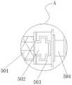
fig. 2 is an enlarged partial cross-sectional view of the utility model at a in fig. 1;
fig. 3 is a schematic view of the elevation structure of the present invention;
FIG. 4 is an enlarged schematic view of the base of the present invention;
fig. 5 is a front view structure diagram of the cleaning mechanism of the present invention.
In the figure: 1. a housing; 2. a material collecting box; 3. a first conduit; 4. a first water pump; 5. a filter structure; 501. filtering with a screen; 502. a clamping block; 503. a card slot; 504. a fixing sheet; 6. a lifting structure; 601. a sleeve; 602. a loop bar; 603. a hose; 604. mounting holes; 605. fixing the bolt; 606. a material tray; 7. a cleaning mechanism; 701. a drive motor; 702. a drive shaft; 703. a connecting plate; 704. a squeegee; 705. brushing a disc; 8. a collection box; 9. a second water pump; 10. a second conduit; 11. a base; 12. a non-slip mat.
Detailed Description
The technical solutions in the embodiments of the present invention will be described clearly and completely with reference to the accompanying drawings in the embodiments of the present invention, and it is obvious that the described embodiments are only some embodiments of the present invention, not all embodiments. Based on the embodiments in the present invention, all other embodiments obtained by a person skilled in the art without creative work belong to the protection scope of the present invention.
Referring to fig. 1-5, the present invention provides an embodiment: a coolant wastewater degreasing device for a machine tool comprises a shell 1 and a collecting box 8, wherein one side of the shell 1 is fixedly connected with a collecting box 2, one end of the collecting box 2 is fixedly connected with a first guide pipe 3, the first guide pipe 3 is fixedly connected with a first water pump 4, the type of the first water pump 4 can be 300QSZ-3.4-13, and a filtering structure 5 is arranged inside the shell 1;
a filter screen 501, a clamping block 502, a clamping groove 503 and a fixing piece 504 are sequentially arranged in the filtering structure 5, the fixing pieces 504 are respectively and fixedly connected to two sides in the shell 1, the clamping groove 503 is fixedly connected to one side of each fixing piece 504, the filter screen 501 is arranged between the clamping grooves 503, and the clamping blocks 502 are fixedly connected to two sides of the filter screen 501;
the width of the outer part of the fixture block 502 is smaller than that of the inner part of the clamping groove 503, the fixture block 502 is embedded in the clamping groove 503, and a clamping structure is formed between the fixture block 502 and the clamping groove 503;
specifically, as shown in fig. 1 and fig. 2, when the mechanism is used, firstly, a filter screen 501, a fixture block 502, a clamping groove 503 and a fixing piece 504 are sequentially arranged in a filtering structure, when the mechanism is used, the filter screen 501 is fixed on one side of the fixture block 502 by connecting the fixture block 502, when the fixture block 502 is embedded in the clamping groove 503, the filter screen 501 can filter the coolant with oil stains, the first water pump 4 is started, the leaked waste liquid is collected, when the filter screen 501 has excessive oil stains, the filter screen 501 is detached to clean the filter screen 501, the second water pump 9 is started to suck the separated oil stains away, and the separated coolant waste water can be further purified, so that the cost is reduced;
one side of the top end of the shell 1 is fixedly connected with a lifting structure 6;
the lifting structure 6 is internally provided with a sleeve 601, a loop bar 602, a hose 603, mounting holes 604, fixing bolts 605 and a material tray 606 in sequence, the loop bar 602 is fixedly connected to one side of the top end of the shell 1, the sleeve 601 is sleeved outside the loop bar 602, the mounting holes 604 are uniformly arranged inside the loop bar 602, the fixing bolts 605 are fixedly connected between the loop bar 602 and the sleeve 601, the material tray 606 is fixedly connected between the top ends of the sleeve 601, the hose 603 is fixedly connected to the bottom end of the material tray 606, the bottom end of the hose 603 is fixedly connected to the top end of the shell 1, and the inside of the hose 603 is communicated with the inside of the shell 1;
the mounting holes 604 are arranged in the sleeve rod 602 at equal intervals, and the diameter of the sleeve 601 is larger than that of the sleeve rod 602;
specifically, as shown in fig. 1 and 3, when the mechanism is used, firstly, a sleeve 601, a loop bar 602, a hose 603, a mounting hole 604, a fixing bolt 605 and a material tray 606 are sequentially arranged in the lifting structure 6, when the mechanism is used, the sleeve 601 is fixedly connected to the bottom end of the material tray 606, the fixing bolt 605 is arranged in the sleeve 601, the mounting holes 604 matched with the fixing bolt 605 are uniformly arranged in the loop bar 602, the height of the feed port is adjusted according to actual needs, the feed port is prevented from being too far away from the discharge port of the equipment, the fixing bolt 605 is rotated out of the mounting hole 604 through a tool, the distance between the sleeve 601 and the loop bar 602 is adjusted, a proper position is selected, and then the fixing bolt 605 is rotated into the mounting hole 604, so that the adjustment is completed, and the mechanism is convenient to use;
a cleaning mechanism 7 is fixedly connected inside the shell 1;
a driving motor 701, a driving shaft 702, a connecting plate 703, a scraping plate 704 and a brush disc 705 are sequentially arranged in the cleaning mechanism 7, the driving motor 701 is fixedly connected to the middle position of the top end of the shell 1, the type of the driving motor 701 can be Y90S-2, the driving shaft 702 is vertically and movably connected to the middle position of the top end in the shell 1, the output end of the driving motor 701 is fixedly connected with the driving shaft 702 through a coupler, and the scraping plate 704 is fixedly connected to two sides of the driving shaft 702;
four groups of scrapers 704 are arranged outside the driving shaft 702, and the scrapers 704 are arranged at equal intervals outside the driving shaft 702;
the bottom end of the connecting plate 703 is fixedly connected with a brush disc 705, and the bottom end of the brush disc 705 is contacted with the top end of the filter screen 501;
specifically, as shown in fig. 1, when the mechanism is used, firstly, a driving motor 701, a driving shaft 702, a connecting plate 703, a scraper 704 and a brush disc 705 are sequentially arranged inside the cleaning structure, when the mechanism is used, the driving motor 701 is started to drive the driving shaft 702 to rotate through the driving shaft 702, at this time, the driving shaft 702 drives the scraper 704 to rotate inside the housing 1 through the connecting plate 703, the scraper 704 scrapes oil stains attached to the inner side wall of the housing 1 in the rotating process, and meanwhile, the rotation of the brush disc 705 stirs the inside to improve the filtering speed;
the other side of the outer portion of the shell 1 is fixedly connected with a collecting box 8, one end of the collecting box 8 is fixedly connected with a second guide pipe 10, the second guide pipe 10 is fixedly connected with a second water pump 9, the type of the second water pump 9 can be 300QSZ-5.4-18.5, four corners of the bottom end of the shell 1 are fixedly connected with a base 11, and an anti-slip pad 12 is fixedly connected inside the base 11.
The working principle is as follows: the utility model discloses when using, at first, filter screen 501 is fixed in one side of fixture block 502 through connecting fixture block 502, when fixture block 502 is embedded into the inside of draw-in groove 503, filter screen 501 just can filter the coolant liquid that has the greasy dirt, start first water pump 4, collect the waste liquid down the seepage, when filter screen 501 has too much greasy dirt, pull down filter screen 501 and wash filter screen 501, start second water pump 9, the greasy dirt that will keep apart is siphoned away, the coolant liquid waste water after the separation can further purify, and the cost is reduced.
Afterwards, sleeve 601 is fixedly connected to the bottom end of charging tray 606, fixing bolt 605 is arranged inside sleeve 601, mounting holes 604 matched with fixing bolt 605 are evenly formed inside sleeve rod 602, the height of a feeding port is adjusted according to actual needs, the feeding port is prevented from being too far away from a discharging port of equipment, fixing bolt 605 is rotated out from the inside of mounting holes 604 through tools, the distance between sleeve 601 and sleeve rod 602 is adjusted, a proper position is selected, fixing bolt 605 is rotated into the inside of mounting holes 604, adjustment is completed, and the use is facilitated.
Finally, through starting driving motor 701, driving motor 701 can take driving shaft 702 to rotate through driving shaft 702, and at this moment, driving shaft 702 can drive scraper blade 704 through connecting plate 703 and rotate in the inside of shell 1, and scraper blade 704 can scrape the adnexed greasy dirt of shell 1 inside wall at rotatory in-process, and simultaneously, the rotation of brush dish 705 can stir inside and improve filter speed.
It is obvious to a person skilled in the art that the invention is not restricted to details of the above-described exemplary embodiments, but that it can be implemented in other specific forms without departing from the spirit or essential characteristics of the invention. The present embodiments are therefore to be considered in all respects as illustrative and not restrictive, the scope of the invention being indicated by the appended claims rather than by the foregoing description, and all changes which come within the meaning and range of equivalency of the claims are therefore intended to be embraced therein. Any reference sign in a claim should not be construed as limiting the claim concerned.
Claims (8)
1. The utility model provides a coolant liquid waste water deoiling dirty device for lathe, includes shell (1) and collecting box (8), its characterized in that: one side of the shell (1) is fixedly connected with a material collecting box (2), one end of the material collecting box (2) is fixedly connected with a first conduit (3), a first water pump (4) is fixedly connected on the first conduit (3), a filtering structure (5) is arranged inside the shell (1), one side of the top end of the shell (1) is fixedly connected with a lifting structure (6), the interior of the shell (1) is fixedly connected with a cleaning mechanism (7), the other side of the outer part of the shell (1) is fixedly connected with a collecting box (8), one end of the collecting box (8) is fixedly connected with a second conduit (10), the second conduit (10) is fixedly connected with a second water pump (9), the all fixedly connected with base (11) in four corners of shell (1) bottom, the equal fixedly connected with slipmat (12) in inside of base (11).
2. The coolant wastewater degreasing device for the machine tool as set forth in claim 1, wherein: the filter structure is characterized in that a filter screen (501), clamping blocks (502), clamping grooves (503) and fixing pieces (504) are sequentially arranged inside the filter structure (5), the fixing pieces (504) are fixedly connected to two sides inside the shell (1) respectively, one side of each fixing piece (504) is fixedly connected with the clamping groove (503), the filter screen (501) is arranged between the clamping grooves (503), and the clamping blocks (502) are fixedly connected to two sides of the filter screen (501).
3. The coolant wastewater degreasing device for the machine tool as set forth in claim 2, wherein: the width of the outer part of the fixture block (502) is smaller than the width of the inner part of the clamping groove (503), the fixture block (502) is embedded in the clamping groove (503), and a clamping structure is formed between the fixture block (502) and the clamping groove (503).
4. The coolant wastewater degreasing device for the machine tool as set forth in claim 1, wherein: the inside of elevation structure (6) has set gradually sleeve (601), loop bar (602), hose (603), mounting hole (604), fixing bolt (605) and charging tray (606), loop bar (602) fixed connection is in one side on shell (1) top, sleeve (601) have all been cup jointed to the outside of loop bar (602), the inside of loop bar (602) all evenly is provided with mounting hole (604), equal fixedly connected with fixing bolt (605) between loop bar (602) and sleeve (601), fixedly connected with charging tray (606) between the top of sleeve (601), and bottom fixedly connected with hose (603) of charging tray (606), the bottom of hose (603) and the top fixed connection of shell (1), the inside of hose (603) is linked together with the inside of shell (1).
5. The coolant wastewater degreasing device for the machine tool as set forth in claim 4, wherein: the mounting holes (604) are arranged in the sleeve rod (602) at equal intervals, and the diameter of the sleeve (601) is larger than that of the sleeve rod (602).
6. The coolant wastewater degreasing device for the machine tool as set forth in claim 1, wherein: the inside of clean mechanism (7) has set gradually driving motor (701), drive shaft (702), connecting plate (703), scraper blade (704) and brush dish (705), driving motor (701) fixed connection is in the intermediate position department on shell (1) top, the vertical swing joint of drive shaft (702) is in the intermediate position department on the inside top of shell (1), the output of driving motor (701) passes through shaft coupling and drive shaft (702) fixed connection, the equal fixedly connected with scraper blade (704) in both sides of drive shaft (702).
7. The coolant wastewater degreasing device for the machine tool as set forth in claim 6, wherein: four groups of scrapers (704) are arranged outside the driving shaft (702), and the scrapers (704) are arranged at equal intervals outside the driving shaft (702).
8. The coolant wastewater degreasing device for the machine tool as set forth in claim 6, wherein: the bottom end of the connecting plate (703) is fixedly connected with a brush disc (705), and the bottom end of the brush disc (705) is contacted with the top end of the filter screen (501).
Priority Applications (1)
| Application Number | Priority Date | Filing Date | Title |
|---|---|---|---|
| CN202123315698.0U CN217103154U (en) | 2021-12-27 | 2021-12-27 | Coolant liquid waste water degreasing device for lathe |
Applications Claiming Priority (1)
| Application Number | Priority Date | Filing Date | Title |
|---|---|---|---|
| CN202123315698.0U CN217103154U (en) | 2021-12-27 | 2021-12-27 | Coolant liquid waste water degreasing device for lathe |
Publications (1)
| Publication Number | Publication Date |
|---|---|
| CN217103154U true CN217103154U (en) | 2022-08-02 |
Family
ID=82590529
Family Applications (1)
| Application Number | Title | Priority Date | Filing Date |
|---|---|---|---|
| CN202123315698.0U Active CN217103154U (en) | 2021-12-27 | 2021-12-27 | Coolant liquid waste water degreasing device for lathe |
Country Status (1)
| Country | Link |
|---|---|
| CN (1) | CN217103154U (en) |
-
2021
- 2021-12-27 CN CN202123315698.0U patent/CN217103154U/en active Active
Similar Documents
| Publication | Publication Date | Title |
|---|---|---|
| CN211985274U (en) | Cleaning tool cleaning device | |
| CN219925579U (en) | Polishing device for electromechanical equipment parts | |
| CN217103154U (en) | Coolant liquid waste water degreasing device for lathe | |
| CN219005732U (en) | Anti-blocking grinding machine | |
| CN211361561U (en) | Dust collector for digit control machine tool | |
| CN116078710B (en) | Antibiotic mould proof belt cleaning device for mahogany furniture | |
| CN218136991U (en) | Optical lens milling and grinding equipment | |
| CN212887065U (en) | Novel sweeps is collected for cylindrical grinder device | |
| CN214351197U (en) | Chip washing device of machining center | |
| CN215613599U (en) | Casing cleaning machine with automatic flip structure | |
| CN213765390U (en) | Grinding device | |
| CN214712345U (en) | Cleaning and collecting device for disc type sheet production workshop | |
| CN114453983A (en) | Main shaft module gantry machining center machine for full-automatic five-surface machining | |
| CN219113683U (en) | Jade polishing workbench waste liquid collecting device | |
| CN219425178U (en) | Cleaning structure for stirrer | |
| CN212653204U (en) | Polisher convenient to wash | |
| CN220094023U (en) | Polishing and soil removing device for aluminum templates | |
| CN221361581U (en) | Precision part cleaning equipment for machining mechanical parts | |
| CN221185731U (en) | CNC is garbage collection device for lathe processing | |
| CN217990214U (en) | Circulating belt cleaning device of commodity station stirring transport vechicle | |
| CN220328048U (en) | Petroleum drilling mud processing device | |
| CN211613577U (en) | Motor spindle production belt cleaning device | |
| CN210936077U (en) | Automatic cleaning device for surface grinding machine workbench | |
| CN221659000U (en) | High-performance high-precision numerical control surface grinding machine convenient for scrap iron cleaning | |
| CN220426162U (en) | Grading crushed stone water recycling device |
Legal Events
| Date | Code | Title | Description |
|---|---|---|---|
| GR01 | Patent grant | ||
| GR01 | Patent grant |