CN217095524U - Ejecting device - Google Patents
Ejecting device Download PDFInfo
- Publication number
- CN217095524U CN217095524U CN202220350226.4U CN202220350226U CN217095524U CN 217095524 U CN217095524 U CN 217095524U CN 202220350226 U CN202220350226 U CN 202220350226U CN 217095524 U CN217095524 U CN 217095524U
- Authority
- CN
- China
- Prior art keywords
- rod
- ejection
- template
- pole
- cylinder body
- Prior art date
- Legal status (The legal status is an assumption and is not a legal conclusion. Google has not performed a legal analysis and makes no representation as to the accuracy of the status listed.)
- Active
Links
Images
Landscapes
- Forging (AREA)
Abstract
The utility model discloses an ejection device, which comprises a forging mechanism, an ejection mechanism and a template for forming a casting, wherein the forging mechanism comprises a first rod for forging and pressing the casting, the ejection mechanism comprises a first connecting part and a second rod for ejecting the casting, the first connecting part is sleeved on the periphery of the first rod, the first connecting part is movably connected with the first rod, the forging end of the first rod is connected with the template, one end of the second rod is fixedly connected with the first connecting part, the other end of the second rod is connected with the template, the first connecting part drives the second rod to move along the length direction of the first rod, the template is provided with a through hole for the first rod and the second rod to pass through, the ejection device has simple structure and easy assembly, ensures that the casting is stressed evenly, and improves the molding quality of the casting, the casting rejection rate is reduced, the production cost is reduced, and the production efficiency is improved.
Description
Technical Field
The utility model is used for forging and pressing device technical field especially relates to an ejecting device.
Background
The liquid forging machine is a machine for casting through hydraulic pressure, the existing liquid forging machine pushes molten metal liquid into a die at a low speed under the action of pressure for extrusion forming, a casting can be obtained after die opening, and the casting can be produced and manufactured through the liquid forging machine in industrial production.
SUMMERY OF THE UTILITY MODEL
An object of the utility model is to solve one of the technical problem that exists among the prior art at least, provide an ejecting device, its quality that can improve the foundry goods reduces the drawing of patterns disability rate of foundry goods.
The utility model provides a technical scheme that its technical problem adopted is:
the utility model provides an ejection device, includes forging mechanism, ejection mechanism and is used for forming the template of foundry goods, forging mechanism is including the first pole that is used for forging and pressing the foundry goods, ejection mechanism includes first connecting part and is used for ejecting foundry goods second pole, first connecting part cover is established the periphery of first pole, first connecting part with first pole swing joint, the forging and pressing end of first pole with the template links to each other, the one end of second pole with first connecting part fixed connection, the other end of second pole with the template links to each other, first connecting part drives the second pole is followed the length direction motion of first pole, be equipped with the confession in the template first pole with the through-hole that the second pole passed.
Preferably, the forging mechanism includes first cylinder body and first piston, be equipped with the confession in the first cylinder body first piston reciprocating motion's first inner chamber, first piston with first pole fixed connection, ejection mechanism includes second cylinder body and second piston, be equipped with the confession in the second cylinder body second piston reciprocating motion's second inner chamber, the second piston cover is established the periphery of first pole, the second piston with first connecting part fixed connection, first cylinder body with second cylinder body fixed connection.
Preferably, the first cylinder body and the second cylinder body are both hydraulic cylinders.
Preferably, a second connecting part is arranged between the first cylinder body and the second cylinder body, the first cylinder body and the second cylinder body are fixedly connected through the second connecting part, a third rod is arranged between the second connecting part and the template, and the second connecting part is fixedly connected with the template through the third rod.
Preferably, the first connecting part includes a first ejecting part provided inside the second cylinder and a second ejecting part provided outside the second cylinder, the first ejecting part is connected to the second piston, and the second ejecting part connects the first ejecting part to the second rod.
Preferably, the second ejection part is an ejection plate, the ejection plate is movably connected with the third rod, and a through hole for the third rod to pass through is formed in the ejection plate.
Preferably, the second rod comprises a fixed rod and an ejector rod, the fixed rod is fixedly connected with the ejector plate, and the ejector rod is detachably connected with the fixed rod.
Preferably, the second rod is provided in plurality, and the plurality of second rods are arranged around the periphery of the first rod.
Preferably, the die plate comprises a fixed die plate for being installed in a liquid forging machine, and the fixed die plate is provided with a through hole for the first rod and the second rod to pass through.
Preferably, the die plate comprises a movable die plate for demolding, and the movable die plate is arranged at one end far away from the ejection mechanism.
One of the above technical solutions has at least one of the following advantages or beneficial effects: the first rod of the ejection device forging mechanism is used for extruding castings, so that the density of the castings is improved, before the templates are opened, the first rod moves along the length direction and stretches into the templates to extrude the castings, the density of the castings is improved, the condition that the thicknesses of the castings are not uniform is avoided, the second rod of the ejection mechanism can eject the castings out of the templates, after the templates are opened, the second rod is driven to move along the length direction of the first rod, the castings are ejected out of the templates by stretching into the templates, the ejection device is simple in structure and easy to assemble, the stress of the castings is uniform, the forming quality of the castings is improved, and the rejection rate of the castings is reduced.
Additional aspects and advantages of the invention will be set forth in part in the description which follows and, in part, will be obvious from the description, or may be learned by practice of the invention.
Drawings
The above and/or additional aspects and advantages of the present invention will become apparent and readily appreciated from the following description of the embodiments, taken in conjunction with the accompanying drawings of which:
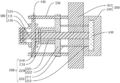
fig. 1 is a cross-sectional view of an embodiment of the present invention.
Detailed Description
This section will describe in detail the embodiments of the present invention, preferred embodiments of the present invention are shown in the attached drawings, which are used to supplement the description of the text part of the specification with figures, so that one can intuitively and vividly understand each technical feature and the whole technical solution of the present invention, but they cannot be understood as the limitation of the protection scope of the present invention.
In the present invention, if there is a description of directions (up, down, left, right, front and back), it is only for convenience of description of the technical solution of the present invention, and it is not intended to indicate or imply that the technical features indicated must have a specific orientation, be constructed and operated in a specific orientation, and thus should not be construed as limiting the present invention.
In the utility model, the meaning of a plurality of is one or more, the meaning of a plurality of is more than two, and the meaning of more than two is understood as not including the number; the terms "above", "below", "within" and the like are understood to include the instant numbers. In the description of the present invention, if there is any description of "first" and "second" only for the purpose of distinguishing technical features, it is not to be understood as indicating or implying relative importance or implicitly indicating the number of indicated technical features or implicitly indicating the precedence of the indicated technical features.
In the present invention, unless otherwise explicitly defined, the terms "set", "install", "connect", and the like are to be understood in a broad sense, and for example, may be directly connected or may be indirectly connected through an intermediate medium; can be fixedly connected, can also be detachably connected and can also be integrally formed; may be mechanically coupled, may be electrically coupled or may be capable of communicating with each other; either as communication within the two elements or as an interactive relationship of the two elements. The technical skill in the art can reasonably determine the specific meaning of the above words in the present invention by combining the specific contents of the technical solution.
The embodiment of the present invention provides an ejection apparatus, referring to fig. 1, including a forging mechanism 100, an ejection mechanism 200 and a template 300 for forming a casting 600, the forging mechanism 100 includes a first rod 110 for forging the casting 600, the first rod 110 is used for extruding the casting 600 to improve the compactness of the casting 600, the ejection mechanism 200 includes a first connecting component 220 and a second rod 210 for ejecting the casting 600, the second rod 210 can eject the casting 600 from the template 300, the first connecting component 220 is sleeved on the periphery of the first rod 110, the first connecting component 220 is movably connected with the first rod 110, the forged end of the first rod 110 is connected with the template 300, one end of the second rod 210 is fixedly connected with the first connecting component 220, the other end of the second rod 210 is connected with the template 300, the first connecting component 220 drives the second rod 210 to move along the length direction of the first rod 110, the template 300 is provided with a through hole for the first rod 110 and the second rod 210 to pass through, before the template 300 is opened, the first rod 110 moves along the length direction and extends into the template 300 to extrude the casting 600, the density of the casting 600 is improved, the condition that the thickness of the casting 600 is not uniform is avoided, then the template 300 is opened, the second rod 210 is driven to move along the length direction of the first rod 110 and extends into the template 300 to eject the casting 600 from the template 300, and the forging mechanism 100 and the ejection mechanism 200 can be separately adjusted and controlled, so that the stress of the casting 600 is uniform, the forming quality is improved, the ejection device is simple in structure and easy to assemble, the uniform stress of the casting is realized, the casting quality is improved, the casting rejection rate is reduced, the production cost is effectively reduced, and the production efficiency is improved.
Referring to fig. 1, the forging mechanism 100 includes a first cylinder 120 and a first piston 130, a first inner cavity for reciprocating the first rod 110 is provided in the first cylinder 120, the first rod 110 is fixedly connected to the first rod 110, the ejection mechanism 200 includes a second cylinder 230 and a second piston 240, a second inner cavity for reciprocating the second piston 240 is provided in the second cylinder 230, the second piston 240 is sleeved on the outer circumference of the first rod 110, the second piston 240 is fixedly connected to a first connecting part 220, and the first cylinder 120 is fixedly connected to the second cylinder 230. According to the technical requirements of different product requirements, the temperature of the first rod 110 and the pressure and the speed of the first rod for extruding the casting 600 are controlled by adjusting the parameters of the first cylinder 120 such as the pressure, the temperature and the speed to improve the density of the casting 600, the temperature of the first connecting part 220 and the second rod 210 and the pressure and the speed for ejecting the casting 600 are controlled by adjusting the parameters of the second cylinder 230 such as the pressure, the temperature and the speed to realize uniform stress on the casting 600, improve the quality of the casting 600 and reduce the rejection rate of the casting.
As a preferred embodiment of the present invention, the first cylinder 120 and the second cylinder 230 are hydraulic cylinders, the first rod 100 is pressed by hydraulic pressure to extrude the casting 600, and the second rod 210 is pressed by hydraulic pressure to eject the casting 600.
Referring to fig. 1, a second connecting member 400 is disposed between the first cylinder and the second cylinder 230, the second connecting member 400 fixedly connects the first cylinder 120 and the second cylinder 230, a third rod 500 is disposed between the second connecting member 400 and the mold plate 300, the second connecting member 400 is fixedly connected to the mold plate 300 through the third rod 500, preferably, 4 third rods 500 are disposed, the second connecting member 400 is a connecting plate, and the third rod 500 fixes four corners of the connecting plate to the mold plate 300.
Referring to fig. 1, the first connection part 220 includes a first ejecting part 221 provided inside the second cylinder 230 and a second ejecting part 222 provided outside the second cylinder 230, the first ejecting part 221 being connected to the second piston 240, the second ejecting part 222 connecting the first ejecting part 221 to the second rod 210.
Referring to fig. 1, the second ejection member 222 is an ejection plate 222, the ejection plate 222 is movably connected to a third rod 500, a through hole for the third rod 500 to pass through is formed in the ejection plate 222, and the third rod 500 provides a guiding and supporting function for the second ejection member 222.
Referring to fig. 1, the second rod 210 includes a fixed rod 211 and an ejector rod 212, the fixed rod 211 is fixedly connected to the ejector plate 222, the ejector rod 212 is detachably connected to the fixed rod 211, and the ejector rod 212 can be replaced according to the size of the mold 300 during use, so as to eject the casting 300 from the mold 300.
Preferably, the number of the second rods 210 is more than one, and the plurality of second rods 210 are arranged around the periphery of the first rod 110, so that the casting 600 is uniformly stressed and smoothly ejected, and preferably, the number of the second rods 210 is 4, and the second rods are arranged around the periphery of the first rod 110.
Referring to fig. 1, the die plate 300 includes a fixed die plate 310 for installation in the liquid forging machine, and the fixed die plate 310 is provided with through holes for the first and second rods 110 and 210 to pass through, so that the ejection device is conveniently installed in the liquid forging machine, and is integrally formed with the liquid forging machine for convenient use.
Referring to fig. 1, the mold plate 300 includes a movable mold plate 320 for demolding, the movable mold plate 320 being disposed at an end remote from the ejection mechanism 200 so as to open the mold plate 300 for ejection of the casting 600.
The installation method of the ejection device comprises the following steps:
the method comprises the following steps: the second piston 240 is sleeved on the first rod 110, and the second connecting part 400 is sleeved on the first rod 110;
step two: the first piston 130 is fitted over the first rod 110;
step three: the first ejection part 221 is fitted over the first rod 110;
step four: the first cylinder 120 is sleeved on one end of the first rod 110, so that the first piston 130 is positioned in the first inner cavity of the first cylinder 120, and the first cylinder 120 is fixedly connected with the second connecting member 400 by using a screw;
step five: the second cylinder 230 is sleeved on the second piston 240, so that the second piston 240 is located in the second inner cavity of the second cylinder 230, and the second cylinder 230 is fixedly connected with the second connecting part 400 by using screws;
step six: sleeving the second ejection part 222 on the first rod 110, and fixedly connecting the second ejection part 222 and the first ejection part 221 through screws;
step seven: the four corners of the second connecting part 400 and the second ejection part 222 are respectively inserted into the third rod 500, the second connecting part 400 and the third rod 500 are fixedly connected through nuts, the second ejection part 222 and the third rod 500 are not fixed and are movably connected, and in the working process, the third rod 500 provides a guiding and supporting function for the second ejection part 222;
step eight: after the above assembly is completed, the above structure is integrally mounted on the template 300 in the liquid forging machine by confirmation and debugging.
In the description herein, references to the description of the term "example," "an embodiment," or "some embodiments," etc., mean that a particular feature, structure, material, or characteristic described in connection with the embodiment or example is included in at least one embodiment or example of the invention. In this specification, the schematic representations of the terms used above do not necessarily refer to the same embodiment or example. Furthermore, the particular features, structures, materials, or characteristics described may be combined in any suitable manner in any one or more embodiments or examples.
The invention is not limited to the above embodiments, and those skilled in the art can make equivalent modifications or substitutions without departing from the spirit of the invention, and such equivalent modifications or substitutions are included in the scope defined by the claims of the present application.
Claims (10)
1. An ejection device, characterized in that: including forging mechanism, ejection mechanism and the template that is used for forming the foundry goods, forging mechanism is including the first pole that is used for forging and pressing the foundry goods, ejection mechanism includes first connecting part and is used for ejecting foundry goods second pole, first connecting part cover is established the periphery of first pole, first connecting part with first pole swing joint, the forging and pressing end of first pole with the template links to each other, the one end of second pole with first connecting part fixed connection, the other end of second pole with the template links to each other, first connecting part drives the second pole is followed the length direction motion of first pole, be equipped with the confession in the template first pole with the through-hole that the second pole passed.
2. The ejection device of claim 1, wherein: forging mechanism includes first cylinder body and first piston, be equipped with the confession in the first cylinder body first piston reciprocating motion's first inner chamber, first piston with first pole fixed connection, ejection mechanism includes second cylinder body and second piston, be equipped with the confession in the second cylinder body second piston reciprocating motion's second inner chamber, the second piston cover is established the periphery of first pole, the second piston with first connecting part fixed connection, first cylinder body with second cylinder body fixed connection.
3. The ejection device of claim 2, wherein: the first cylinder body and the second cylinder body are hydraulic cylinders.
4. The ejection device of claim 2, wherein: and a second connecting part is arranged between the first cylinder body and the second cylinder body, the second connecting part fixedly connects the first cylinder body and the second cylinder body, a third rod is arranged between the second connecting part and the template, and the second connecting part is fixedly connected with the template through the third rod.
5. The ejection device of claim 4, wherein: the first connecting part comprises a first ejection part arranged inside the second cylinder body and a second ejection part arranged outside the second cylinder body, the first ejection part is connected with the second piston, and the second ejection part connects the first ejection part with the second rod.
6. The ejection device of claim 5, wherein: the second ejection part is an ejection plate, the ejection plate is movably connected with the third rod, and a through hole for the third rod to pass through is formed in the ejection plate.
7. The ejection device of claim 6, wherein: the second rod comprises a fixed rod and an ejector rod, the fixed rod is fixedly connected with the ejector plate, and the ejector rod is detachably connected with the fixed rod.
8. The ejection device of claim 7, wherein: the second rod is provided with a plurality of, a plurality of the second rod is around setting up in the periphery of first pole.
9. The ejection device of claim 1, wherein: the template comprises a fixed template which is used for being installed in a liquid forging machine, and through holes for the first rods and the second rods to penetrate through are formed in the fixed template.
10. Ejection device according to claim 9, characterized in that: the template comprises a movable template for demolding, and the movable template is arranged at one end far away from the ejection mechanism.
Priority Applications (1)
| Application Number | Priority Date | Filing Date | Title |
|---|---|---|---|
| CN202220350226.4U CN217095524U (en) | 2022-02-21 | 2022-02-21 | Ejecting device |
Applications Claiming Priority (1)
| Application Number | Priority Date | Filing Date | Title |
|---|---|---|---|
| CN202220350226.4U CN217095524U (en) | 2022-02-21 | 2022-02-21 | Ejecting device |
Publications (1)
| Publication Number | Publication Date |
|---|---|
| CN217095524U true CN217095524U (en) | 2022-08-02 |
Family
ID=82599280
Family Applications (1)
| Application Number | Title | Priority Date | Filing Date |
|---|---|---|---|
| CN202220350226.4U Active CN217095524U (en) | 2022-02-21 | 2022-02-21 | Ejecting device |
Country Status (1)
| Country | Link |
|---|---|
| CN (1) | CN217095524U (en) |
-
2022
- 2022-02-21 CN CN202220350226.4U patent/CN217095524U/en active Active
Similar Documents
| Publication | Publication Date | Title |
|---|---|---|
| CN203003115U (en) | Die-casting die for manufacturing wind blade | |
| CN217095524U (en) | Ejecting device | |
| CN216325006U (en) | Local extrusion device of horizontal die casting machine | |
| CN210553225U (en) | Portable demoulding structure of hardware mould | |
| CN213166779U (en) | Cable color bar extrusion die | |
| CN210702460U (en) | Die casting round pin quick change mechanism under die casting die | |
| CN217775519U (en) | Oil pressure cable-stayed hot chamber die casting machine for open-close die | |
| CN213530714U (en) | Die-casting die for deep-cavity thin-wall shell | |
| CN214027018U (en) | Ejector rod quick-change structure | |
| CN110789066A (en) | Six-way pipe fitting injection mold | |
| CN217098603U (en) | Double-colored scissors device of moulding plastics | |
| CN215467984U (en) | Die-casting die for brake handle of motor vehicle | |
| CN210615077U (en) | Local extrusion mechanism of mould | |
| CN217648862U (en) | Mold capable of effectively shortening main runner | |
| CN219581672U (en) | Diamond tool bit mould capable of rapidly opening mould | |
| CN220612256U (en) | Die casting die of compressor bracket | |
| CN216968532U (en) | Air guide type step combined die | |
| CN211052483U (en) | Washing machine components of a whole that can function independently axle is convenient for pressfitting form removal's mould | |
| CN209379884U (en) | Extruding pin assembly for thin-wall product | |
| CN220464606U (en) | Silica gel return bend forming die | |
| CN220826251U (en) | Injection mold forming device | |
| CN215039753U (en) | Injection mold for plastic products convenient for rapid demoulding | |
| CN218053721U (en) | Automatic ejection device for injection mold | |
| CN216884909U (en) | Injection molding and punching die for producing parts with holes | |
| CN210908046U (en) | Automobile parts die casting die convenient to dismantle |
Legal Events
| Date | Code | Title | Description |
|---|---|---|---|
| GR01 | Patent grant | ||
| GR01 | Patent grant |