CN217093621U - Feed arrangement is used in rice processing with adjustable flow - Google Patents
Feed arrangement is used in rice processing with adjustable flow Download PDFInfo
- Publication number
- CN217093621U CN217093621U CN202122455514.4U CN202122455514U CN217093621U CN 217093621 U CN217093621 U CN 217093621U CN 202122455514 U CN202122455514 U CN 202122455514U CN 217093621 U CN217093621 U CN 217093621U
- Authority
- CN
- China
- Prior art keywords
- fixedly connected
- plate
- fixed
- motor
- limiting
- Prior art date
- Legal status (The legal status is an assumption and is not a legal conclusion. Google has not performed a legal analysis and makes no representation as to the accuracy of the status listed.)
- Active
Links
Images


Abstract
The utility model provides a feed arrangement is used in rice processing with adjustable flow relates to rice processing technology field, the framework top is close to the fixed frame of right side fixedly connected with of department, there is first motor at fixed frame top, the first transmission pole of first motor power output shaft fixedly connected with, fixed frame top is run through to first transmission pole bottom to fixedly connected with disc, the disc bottom is close to right side fixedly connected with fixed block of department, fixed block inner chamber articulates there is the connection cross rod, through mutually supporting between first motor, fixed block, gag lever post, the removal post isotructure, can realize that first motor drives first transmission pole and rotate, and first transmission pole drives and connects U template and spacing U template and rotate, and spacing U template drives the removal post and reciprocates to the flow of control rice feeding.
Description
Technical Field
The utility model relates to a rice processing field, more specifically is a feed arrangement is used in rice processing with adjustable flow.
Background
The rice is a finished product prepared by cleaning, milling and finishing the rice, is a basic food for supplementing nutrition, is an essential food on dining tables of people, is rich in carbohydrate, also contains protein, fat, vitamins and the like, and is easy to generate impurities when being stocked due to large stocked amount.
However, the existing feeding device for rice processing has some problems in use, the existing feeding device cannot control and adjust the feeding speed of the rice in use, the workload of the device is improved, and meanwhile, impurities in the rice cannot be screened.
SUMMERY OF THE UTILITY MODEL
In order to solve current feed arrangement in use can not control the regulation to the input speed of rice, improved the work load nature of device, can not sieve the impurity in the rice simultaneously, the utility model aims at providing a feed arrangement is used in rice processing with adjustable flow.
In order to achieve the above purpose, the utility model adopts the following technical scheme: a flow adjustable feeding device for rice processing, the rice processing comprises:
a frame body, a fixed frame is fixedly connected at the top of the frame body close to the right side, a first motor is arranged at the top of the fixed frame, a first transmission rod is fixedly connected with a power output shaft of the first motor, the bottom end of the first transmission rod penetrates through the top of the fixed frame and is fixedly connected with a disc, a fixed block is fixedly connected at the bottom of the disc close to the right side, a connecting cross rod is hinged in an inner cavity of the fixed block, the outer edge of the connecting cross rod is hinged with a connecting U-shaped plate, a limiting rod is fixedly connected at the bottom of the connecting U-shaped plate, a limiting U-shaped plate is fixedly connected at the bottom of the limiting rod, a limiting cross rod is hinged in an inner cavity of the limiting U-shaped plate, a round pipe is arranged at the top of the frame body close to the right side in a penetrating manner and is fixedly connected with the top end of the round pipe, the top end of the round pipe penetrates through the bottom of the fixed frame and is fixedly connected with the fixed frame, a moving column is arranged in an inner cavity of the round pipe, and a limiting block is fixedly connected with the top end of the moving column, the top of the limiting block is hinged to the edge of the outer side of the limiting cross rod, and the left side of the fixing frame is fixedly connected with a feeding pipe;
the right side of the fixed plate is fixedly connected to the left side of the frame body and close to the rear side, a second motor is arranged at the rear side of the fixed plate and close to the right side, a power output shaft of the second motor is fixedly connected with a second transmission rod, the front end of the second transmission rod is inserted into the rear side of the fixed plate, a first grooved pulley is sleeved on the outer edge of the second transmission rod, a second grooved pulley is arranged on the left side of the first grooved pulley, a belt is arranged between the first grooved pulley and the second grooved pulley, the first grooved pulley and the second grooved pulley are movably connected through the belt, a rotating rod is fixedly connected to the circle center of the second grooved pulley, the front end of the rotating rod is inserted into the rear side of the fixed plate, a sliding groove is arranged on the front side of the fixed plate, a movable groove is arranged on the rear side of an inner cavity of the sliding groove, a movable plate is movably connected to the inner cavity of the sliding groove, two fixed columns are fixedly connected to the rear side of the movable plate, and cylinders are fixedly connected to the top and the bottom of the front side of the fixed plate, the cylinder outside edge fixedly connected with spring, the equal fixedly connected with connecting plate of movable plate top and bottom center department, the connecting plate front side all articulates there is the swing piece, cylindrical one end fixed connection in adjacent swing piece one side is kept away from to the spring.
Preferably, the framework left and right sides is the opening setting, there is the conveyer belt framework inner chamber, the equal fixedly connected with backup pad in both sides around the conveyer belt, common fixed connection in framework inner chamber bottom is in the backup pad bottom.
Preferably, the left side of the conveying belt is provided with an inclined plate, and the front side and the rear side of the inclined plate are fixedly connected to the side wall of the inner cavity of the frame.
Preferably, fixed frame top fixedly connected with protection casing, first motor top fixed connection is at protection casing inner chamber top, the protection casing bottom sets up for the opening.
Preferably, the rear end of the fixing column penetrates through the movable groove, and supporting columns are fixedly connected to the front sides of the first grooved wheel and the second grooved wheel.
Preferably, the top of the second motor is fixedly connected with an L-shaped plate, and one side of the L-shaped plate, which is far away from the second motor, is fixedly connected to the rear side of the fixing plate.
Preferably, the front side of the moving plate is fixedly connected with a collecting frame, and the bottom of the collecting frame is provided with a plurality of filtering holes.
Compared with the prior art, the utility model discloses the beneficial effect who realizes:
1. in the utility model, through the mutual cooperation among the structures such as the first motor, the fixed block, the limiting rod, the movable column and the like, the first motor can drive the first transmission rod to rotate, the first transmission rod drives the connecting U-shaped plate and the limiting U-shaped plate to rotate, and the limiting U-shaped plate drives the movable column to move up and down, thereby controlling the flow rate of rice feeding;
2. the utility model discloses in, through mutually supporting between second motor, movable plate, spring, fixed column isotructure, can realize that the second motor drives the second transfer line and rotates, the second transfer line drives first sheave and second sheave and rotates, and first sheave and second sheave drive the fixed column through the support column and remove about, and the fixed column drives and collects the frame and remove to impurity in the rice sieves.
Drawings
The invention is described in further detail below with reference to the following figures and detailed description:
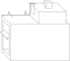
FIG. 1 is a perspective view of a component frame of the present invention;
fig. 2 is a front sectional view of the present invention;
fig. 3 is a rear sectional view of the present invention;
fig. 4 is a front view of the present invention.
The structure in the figure is as follows: 1. a frame body; 2. a fixing plate; 3. a fixing frame; 4. a first motor; 5. a first drive lever; 6. a disc; 7. a fixed block; 8. connecting a cross rod; 9. connecting the U-shaped plate; 10. a limiting rod; 11. a limiting U-shaped plate; 12. a limiting block; 13. moving the column; 14. a limiting cross rod; 15. a circular tube; 16. a support plate; 17. a conveyor belt; 18. a sloping plate; 19. a cylinder; 20. a spring; 21. a swing block; 22. a connecting plate; 23. moving the plate; 24. fixing a column; 25. a second motor; 26. a second transmission rod; 27. a first sheave; 28. a second sheave; 29. a support pillar; 30. rotating the rod; 31. a belt; 32. and (5) collecting the frame.
Detailed Description
The following description is provided for illustrative purposes, and other advantages and features of the present invention will become apparent to those skilled in the art from the following detailed description.
Referring to fig. 1 to 4, it should be understood that the structures, ratios, sizes, etc. shown in the drawings attached to the present specification are only used for matching with the contents disclosed in the specification, so as to be known and read by those skilled in the art, and are not used for limiting the practical limitations of the present invention, so they do not have the essential significance in the technology, and any modification of the structures, changes of the ratio relationship, or adjustment of the sizes should still fall within the scope of the present invention. Meanwhile, the terms such as "upper", "lower", "left", "right", "middle" and "one" used in the present specification are for convenience of description, and are not intended to limit the scope of the present invention, and changes or adjustments of the relative relationship thereof may be made without substantial technical changes, and the present invention is also regarded as the scope of the present invention.
The utility model provides a feed arrangement is used in rice processing with adjustable flow carries out the detailed description below to each part of a feed arrangement is used in rice processing with adjustable flow:
the frame body 1, a fixed frame 3 is fixedly connected at the position, close to the right side, of the top of the frame body 1, a first motor 4 is arranged at the top of the fixed frame 3, a first transmission rod 5 is fixedly connected to a power output shaft of the first motor 4, the bottom end of the first transmission rod 5 penetrates through the top of the fixed frame 3, a disc 6 is fixedly connected to the bottom of the disc 6, a fixed block 7 is fixedly connected at the position, close to the right side, of the bottom of the disc 6, a connecting cross rod 8 is hinged to an inner cavity of the fixed block 7, a connecting U-shaped plate 9 is hinged to the outer edge of the connecting cross rod 8, a limiting rod 10 is fixedly connected to the bottom of the connecting U-shaped plate 9, a limiting U-shaped plate 11 is fixedly connected to the bottom end of the limiting rod 10, a limiting cross rod 14 is hinged to an inner cavity of the limiting U-shaped plate 11, a circular tube 15 is arranged at the position, close to the right side, of the top of the frame body 1 in a penetrating manner and fixedly connected with the bottom of the fixed frame 3, the top end of the circular tube 15 penetrates through the bottom of the fixed frame 3 and is fixedly connected with the fixed frame, a moving column 13, a limiting block 12 is arranged in the inner cavity of the circular tube 15, the top of a limiting block 12 is hinged to the edge of the outer side of a limiting cross rod 14, the left side of a fixing frame 3 is fixedly connected with a feeding pipe, the top of the fixing frame 3 is fixedly connected with a protective cover, the top of a first motor 4 is fixedly connected to the top of an inner cavity of the protective cover, the bottom of the protective cover is arranged in an opening mode, the left side and the right side of a frame body 1 are both arranged in an opening mode, an inner cavity of the frame body 1 is provided with a conveyor belt 17, the front side and the rear side of the conveyor belt 17 are both fixedly connected with supporting plates 16, the bottoms of the supporting plates 16 are jointly and fixedly connected to the bottom of the inner cavity of the frame body 1, an inclined plate 18 is arranged on the left side and the rear side of the inner cavity of the frame body 1, the first motor 4 drives a first transmission rod 5 to rotate, the first transmission rod 5 drives a connecting U-shaped plate 9 and a limiting U-shaped plate 11 to rotate, the limiting U-shaped plate 11 drives a movable column 13 to move up and down, and accordingly the flow of rice feeding is controlled;
the right side of the fixed plate 2 is fixedly connected to the left side of the frame body 1 close to the rear side, the rear side of the fixed plate 2 close to the right side is provided with a second motor 25, a power output shaft of the second motor 25 is fixedly connected with a second transmission rod 26, the front end of the second transmission rod 26 is inserted into the rear side of the fixed plate 2, the outer edge of the second transmission rod 26 is sleeved with a first grooved pulley 27, the left side of the first grooved pulley 27 is provided with a second grooved pulley 28, a belt 31 is arranged between the first grooved pulley 27 and the second grooved pulley 28, the first grooved pulley 27 and the second grooved pulley 28 are movably connected through the belt 31, the circle center of the second grooved pulley 28 is fixedly connected with a rotating rod 30, the front end of the rotating rod 30 is inserted into the rear side of the fixed plate 2, the front side of the fixed plate 2 is provided with a sliding groove, the rear side of the inner cavity of the sliding groove is provided with a movable groove, the inner cavity of the sliding groove is movably connected with a movable plate 23, the rear side of the movable plate 23 is fixedly connected with two fixed columns 24, the top and the bottom of the front side of the fixed plate 2 are both fixedly connected with columns 19, the outer edge of the cylinder 19 is fixedly connected with a spring 20, the centers of the top and the bottom of a movable plate 23 are fixedly connected with connecting plates 22, the front sides of the connecting plates 22 are hinged with swinging blocks 21, one end of the spring 20 far away from the cylinder 19 is fixedly connected to one side of the adjacent swinging block 21, the front side of the movable plate 23 is fixedly connected with a collecting frame 32, the bottom of the collecting frame 32 is provided with a plurality of filtering holes, the top of a second motor 25 is fixedly connected with an L-shaped plate, one side of the L-shaped plate far away from a second motor 25 is fixedly connected to the rear side of the fixed plate 2, the rear end of the fixed column 24 penetrates through a movable groove, the front sides of the first grooved wheel 27 and the second grooved wheel 28 are fixedly connected with supporting columns 29, the second motor 25 drives a second transmission rod 26 to rotate, the second transmission rod 26 drives the first grooved wheel 27 and the second grooved wheel 28 to rotate, and the first grooved wheel 27 and the second grooved wheel 28 drive the fixed column 24 to move left and right through the supporting columns 29, the fixed column 24 drives the collection frame 32 to move left and right, so that impurities in the rice are screened.
In the using process, an operator pours rice into the feeding pipe, the rice enters the fixed frame 3, the first motor 4 is started through an external power supply, the first motor 4 drives the first transmission rod 5 to rotate, the first transmission rod 5 drives the disc 6 to rotate, the disc 6 drives the fixed block 7 to rotate, the fixed block 7 drives the connecting U-shaped plate 9 to rotate and move up and down through the connecting cross rod 8, the connecting U-shaped plate 9 drives the limiting rod 10 to rotate, the limiting rod 10 drives the limiting U-shaped plate 11 to rotate and move up and down, the limiting U-shaped plate 11 drives the limiting block 12 to move up and down through the limiting cross rod 14, the limiting block 12 drives the moving column 13 to move up and down, thereby the feeding flow of the rice is controlled through the moving column 13, the working efficiency of the device is improved, the rice falls into the top of the conveying belt 17, the conveying belt 17 is started, the conveying belt 17 conveys the rice to the inside of the collection frame 32 through the inclined plate 18, at this time, the second motor 25 is started through an external power supply, the second motor 25 drives the second transmission rod 26 to rotate, the second transmission rod 26 drives the first grooved pulley 27 to rotate, the first grooved pulley 27 drives the second grooved pulley 28 to rotate through the belt 31, the second grooved pulley 28 drives the rotating rod 30 to rotate, the first grooved pulley 27 and the second grooved pulley 28 drive the supporting column 29 to rotate, the supporting column 29 drives the fixed column 24 to move left and right, the fixed column 24 drives the movable plate 23 to move left and right, the movable plate 23 drives the connecting plate 22 to move left and right, the connecting plate 22 drives the swinging block 21 to swing, the swinging block 21 drives the spring 20 to stretch, meanwhile, the movable plate 23 drives the collection frame 32 to move left and right, and the collection frame 32 screens the rice inside.
The above embodiments are merely illustrative of the principles and effects of the present invention, and are not to be construed as limiting the invention. Modifications and variations can be made to the above-described embodiments by those skilled in the art without departing from the spirit and scope of the present invention. Accordingly, it is intended that all equivalent modifications or changes which may be made by those skilled in the art without departing from the spirit and technical spirit of the present invention be covered by the claims of the present invention.
Claims (7)
1. A flow-adjustable feeding device for rice processing, characterized in that the rice processing comprises:
the frame body (1), the top of the frame body (1) is close to a right side and fixedly connected with a fixed frame (3), the top of the fixed frame (3) is provided with a first motor (4), a power output shaft of the first motor (4) is fixedly connected with a first transmission rod (5), the bottom end of the first transmission rod (5) penetrates through the top of the fixed frame (3) and is fixedly connected with a disc (6), the bottom of the disc (6) is close to the right side and fixedly connected with a fixed block (7), the inner cavity of the fixed block (7) is hinged with a connecting cross rod (8), the outer edge of the connecting cross rod (8) is hinged with a connecting U-shaped plate (9), the bottom of the connecting U-shaped plate (9) is fixedly connected with a limiting rod (10), the bottom end of the limiting rod (10) is fixedly connected with a limiting U-shaped plate (11), the inner cavity of the limiting U-shaped plate (11) is hinged with a limiting cross rod (14), a round pipe (15) penetrates through the top of the frame body (1) close to the right side and is fixedly connected with the frame body, the top end of the round pipe (15) penetrates through the bottom of the fixed frame (3) and is fixedly connected with the fixed frame, a moving column (13) is arranged in the inner cavity of the round pipe (15), the top end of the moving column (13) is fixedly connected with a limiting block (12), the top of the limiting block (12) is hinged to the edge of the outer side of a limiting cross rod (14), and the left side of the fixed frame (3) is fixedly connected with a feeding pipe;
the right side of the fixing plate (2) is fixedly connected to the left side of the frame body (1) and close to the rear side, a second motor (25) is arranged at the rear side of the fixing plate (2) and close to the right side, a second transmission rod (26) is fixedly connected to a power output shaft of the second motor (25), the front end of the second transmission rod (26) is inserted into the rear side of the fixing plate (2), a first grooved pulley (27) is sleeved on the outer edge of the second transmission rod (26), a second grooved pulley (28) is arranged on the left side of the first grooved pulley (27), a belt (31) is arranged between the first grooved pulley (27) and the second grooved pulley (28), the first grooved pulley (27) and the second grooved pulley (28) are movably connected through the belt (31), a rotating rod (30) is fixedly connected to the circle center of the second grooved pulley (28), and the front end of the rotating rod (30) is inserted into the rear side of the fixing plate (2), the utility model discloses a swing block, including fixed plate (2), spout (23), fixed plate (2) front side, spout inner chamber rear side, spout inner chamber swing joint has movable plate (23), two fixed columns (24) of movable plate (23) rear side fixedly connected with, fixed plate (2) front side top and bottom department equal fixedly connected with cylinder (19), cylinder (19) outside edge fixedly connected with spring (20), movable plate (23) top and bottom center department equal fixedly connected with connecting plate (22), connecting plate (22) front side all articulates there is swing piece (21), the one end fixed connection that cylinder (19) were kept away from in spring (20) is in adjacent swing piece (21) one side.
2. The feeding device for rice processing with adjustable flow rate of claim 1, wherein: the utility model discloses a conveying belt, including framework (1), conveyer belt (17), the equal fixedly connected with backup pad (16) in both sides around conveyer belt (17), the common fixed connection in framework (1) inner chamber bottom in backup pad (16) bottom is the opening setting for the framework (1) left and right sides, there is conveyer belt (17) framework (1) inner chamber.
3. The feeding device for rice processing with adjustable flow rate of claim 2, wherein: there is swash plate (18) conveyer belt (17) left side, equal fixed connection in framework (1) inner chamber lateral wall in both sides around swash plate (18).
4. The adjustable-flow feeding device for rice processing as claimed in claim 1, wherein: the protection cover is fixedly connected to the top of the fixed frame (3), the top of the first motor (4) is fixedly connected to the top of the inner cavity of the protection cover, and the bottom of the protection cover is provided with an opening.
5. The feeding device for rice processing with adjustable flow rate of claim 1, wherein: the rear end of the fixed column (24) penetrates through the movable groove, and supporting columns (29) are fixedly connected to the front sides of the first grooved wheel (27) and the second grooved wheel (28).
6. The adjustable-flow feeding device for rice processing as claimed in claim 1, wherein: the top of the second motor (25) is fixedly connected with an L-shaped plate, and one side of the L-shaped plate, which is far away from the second motor (25), is fixedly connected to the rear side of the fixing plate (2).
7. The feeding device for rice processing with adjustable flow rate of claim 1, wherein: the front side of the moving plate (23) is fixedly connected with a collecting frame (32), and the bottom of the collecting frame (32) is provided with a plurality of filtering holes.
Priority Applications (1)
| Application Number | Priority Date | Filing Date | Title |
|---|---|---|---|
| CN202122455514.4U CN217093621U (en) | 2021-10-12 | 2021-10-12 | Feed arrangement is used in rice processing with adjustable flow |
Applications Claiming Priority (1)
| Application Number | Priority Date | Filing Date | Title |
|---|---|---|---|
| CN202122455514.4U CN217093621U (en) | 2021-10-12 | 2021-10-12 | Feed arrangement is used in rice processing with adjustable flow |
Publications (1)
| Publication Number | Publication Date |
|---|---|
| CN217093621U true CN217093621U (en) | 2022-08-02 |
Family
ID=82588349
Family Applications (1)
| Application Number | Title | Priority Date | Filing Date |
|---|---|---|---|
| CN202122455514.4U Active CN217093621U (en) | 2021-10-12 | 2021-10-12 | Feed arrangement is used in rice processing with adjustable flow |
Country Status (1)
| Country | Link |
|---|---|
| CN (1) | CN217093621U (en) |
-
2021
- 2021-10-12 CN CN202122455514.4U patent/CN217093621U/en active Active
Similar Documents
| Publication | Publication Date | Title |
|---|---|---|
| CN107414993A (en) | A kind of bamboo product processing, which is used, matches somebody with somebody adhesive dispenser | |
| CN208853241U (en) | A kind of rice processing removal of impurities feed device | |
| CN210527603U (en) | Automatic height-adjusting's grain baling press | |
| CN105725224A (en) | Walnut shell breaking device and using method thereof | |
| CN107231944A (en) | A kind of edible mushroom automatic bottling machine | |
| CN217093621U (en) | Feed arrangement is used in rice processing with adjustable flow | |
| CN208928566U (en) | A kind of multistage oscillatory type Choice of Chinese medicine material device | |
| CN107352283B (en) | Raw coal conveying device | |
| CN113118017A (en) | High-efficient grinder of chinese-medicinal material with multistage screening function | |
| CN113245182A (en) | Sieving mechanism is used in processing of trichosanthes seed | |
| CN206028114U (en) | Red date grader | |
| CN209715738U (en) | A kind of ramulus mori Edible mushroom processing automatic sorting device | |
| CN111151332A (en) | Food grinder and food preparation machine thereof | |
| CN209554396U (en) | A kind of drop type rice material recoil blanking device | |
| CN210632436U (en) | Medicinal material multi-stage screening device for herbal pieces-production | |
| CN114870937A (en) | Colloid mill for producing capsule and tablet | |
| CN110586249B (en) | Equipment for separating wheat bran, wheat germ and endosperm | |
| CN108654788B (en) | Dry tea pre-crushing device containing stem and leaf separation | |
| CN214865286U (en) | Novel honeysuckle is cleaned device | |
| CN208244797U (en) | Devices for husking rice is used in a kind of follow-on rice processing | |
| CN206371396U (en) | A kind of more preferable peeled shrimp impurity removing machine of impurity-eliminating effect | |
| CN108340512A (en) | A kind of plastic processing feed device | |
| CN216064131U (en) | Numerical control screening and shunting device for porridge and rice | |
| CN212975795U (en) | Raw materials sorting facilities is used in nut processing | |
| CN2530738Y (en) | Swinging rotary type screen sieve |
Legal Events
| Date | Code | Title | Description |
|---|---|---|---|
| GR01 | Patent grant | ||
| GR01 | Patent grant |