CN217083670U - Glass thickness measuring device - Google Patents
Glass thickness measuring device Download PDFInfo
- Publication number
- CN217083670U CN217083670U CN202220844759.8U CN202220844759U CN217083670U CN 217083670 U CN217083670 U CN 217083670U CN 202220844759 U CN202220844759 U CN 202220844759U CN 217083670 U CN217083670 U CN 217083670U
- Authority
- CN
- China
- Prior art keywords
- sliding
- guide
- fixed
- glass
- guide plate
- Prior art date
- Legal status (The legal status is an assumption and is not a legal conclusion. Google has not performed a legal analysis and makes no representation as to the accuracy of the status listed.)
- Active
Links
Images
Landscapes
- Length Measuring Devices By Optical Means (AREA)
Abstract
The application discloses a glass thickness measuring device, which relates to the technical field of thickness measurement, and adopts the technical scheme that the glass thickness measuring device comprises a sliding table seat, a clamping piece arranged at the top end of the sliding table seat, longitudinal sliding components fixed on two sides of the sliding table seat, an installation frame arranged on the longitudinal sliding components and a detection component arranged on the installation frame; the longitudinal sliding assembly comprises mounting seats fixed at the top end and the bottom end of the sliding platform seat, a guide rod fixed between the two mounting seats, a sliding block connected to the guide rod in a sliding manner and a transverse connecting rod fixedly connected with the sliding block; the mounting rack is connected with the transverse connecting rod in a sliding manner; the detection assembly comprises a laser thickness gauge arranged on the mounting rack and a driving piece driving the laser thickness gauge to move. This application has the effect that can conveniently carry out thickness detection to large-scale glass's different positions.
Description
Technical Field
The utility model relates to a thickness measurement technical field particularly, relates to a glass thickness measuring device.
Background
At present, glass substrate production lines generally use mechanical thickness gauges, such as vernier calipers and micrometers, to measure the thickness of glass. In actual production, the size of the produced glass is bipolar differentiated, the glass is larger and larger, the glass is smaller and smaller, the thickness of the glass is also the same, the control requirement on the thickness of the glass is stricter, the error of a common mechanical thickness measuring instrument is larger, if a measuring tool such as a micrometer is used for measuring the thickness of a large glass in a central area, the length and the width of the produced glass substrate are more than 2 meters, and the traditional measuring tool is difficult to measure.
SUMMERY OF THE UTILITY MODEL
The utility model discloses a main aim at overcomes prior art's is not enough, provides a glass thickness measuring device, can conveniently carry out thickness detection to large-scale glass's different positions.
In order to achieve the above object, the utility model adopts the following technical scheme: a glass thickness measuring device comprises a sliding table seat, a clamping piece arranged at the top end of the sliding table seat, longitudinal sliding components fixed on two sides of the sliding table seat, an installation frame arranged on the longitudinal sliding components and a detection component arranged on the installation frame; the longitudinal sliding assembly comprises mounting seats fixed at the top end and the bottom end of the sliding platform seat, a guide rod fixed between the two mounting seats, a sliding block connected to the guide rod in a sliding manner and a transverse connecting rod fixedly connected with the sliding block; the mounting rack is connected with the transverse connecting rod in a sliding manner; the detection assembly comprises a laser thickness gauge arranged on the mounting rack and a driving piece driving the laser thickness gauge to move.
Preferably, the detection assembly further comprises a guide plate driven by the driving part to move and a guide block matched with the guide plate, a guide groove for placing the guide block is formed in the guide plate, and the laser thickness gauge is arranged on the guide plate.
Preferably, a floating joint is arranged on one side, close to the glass, of the guide plate, and a vertical shifting fork is fixed at one end, far away from the guide plate, of the floating joint; the vertical shifting fork comprises a connecting part fixedly connected with the floating joint and a guide part vertically fixed at one end, far away from the floating joint, of the connecting part, and the laser thickness gauge is fixed on the connecting part.
Preferably, a guide pillar is vertically fixed at one end of the guide plate, which is far away from the driving part, a connecting plate is connected to the guide pillar in a sliding manner, the floating joint is fixed on the connecting plate, and an elastic part which drives the connecting plate to move in the direction far away from the guide plate is arranged between the guide plate and the connecting plate.
Preferably, an aluminum profile frame is fixed to one side of the slide pedestal.
The utility model discloses following beneficial effect has:
the detection assembly is moved to a position to be detected of the glass through the longitudinal sliding assembly and the mounting frame, the thickness of the glass is detected through the monitoring assembly, and the detection of different positions is convenient for detecting the thickness of the glass at different positions only by driving the detection assembly to different positions through the longitudinal sliding assembly and the mounting frame;
the mutual cooperation between deflector and the guide block can make laser thickness gauge keep stable at the in-process that removes to increase the accuracy of test.
Drawings
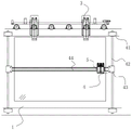
FIG. 1 is a front view of an embodiment;
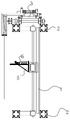
FIG. 2 is a side view of an embodiment;
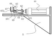
FIG. 3 is a schematic diagram of a structure embodying a detection assembly.
Wherein the figures include the following reference numerals: 1. a slide pedestal; 2. an aluminum profile frame; 3. a clamping member; 4. a longitudinal sliding assembly; 41. a mounting seat; 42. a guide bar; 43. a slider; 44. a transverse connecting rod; 5. a mounting frame; 6. a detection component; 61. a cylinder; 62. a guide plate; 621. a guide groove; 63. a guide post; 64. a spring; 65. a connecting plate; 66. a floating joint; 67. a vertical shifting fork; 671. a connecting portion; 672. a guide portion; 68. a laser thickness gauge; 69. and a guide block.
Detailed Description
The present invention will be further explained with reference to the accompanying drawings.
The technical solutions in the embodiments of the present invention will be clearly and completely described below with reference to the drawings in the embodiments of the present invention, and it is obvious that the described embodiments are only a part of the embodiments of the present invention, and not all of the embodiments. All other embodiments, which can be derived by a person skilled in the art from the embodiments given herein without making any creative effort, shall fall within the protection scope of the present invention.
Example (b): a glass thickness measuring device, see fig. 1 and 2, includes slide pedestal 1, fixes aluminium alloy frame 2 in slide pedestal 1 one side, installs holder 3 on slide pedestal 1 top, fixes the vertical subassembly 4 that slides in slide pedestal 1 both sides, installs mounting bracket 5 on vertical subassembly 4 that slides and sets up the detection component 6 on mounting bracket 5.
The longitudinal sliding assembly 4 comprises mounting seats 41 fixed at the top end and the bottom end of the sliding platform base 1, a guide rod 42 fixed between the two mounting seats 41, a sliding block 43 connected to the guide rod 42 in a sliding manner, and a transverse connecting rod 44 fixedly connected with the sliding block 43.
The number of the guide rods 42 is two, and the guide rods are symmetrically arranged on two sides of the slide pedestal 1, and the corresponding mounting seats 41 are also fixed on two sides of the slide pedestal 1. The two guide rods 42 are both vertically arranged, and the two sliding blocks 43 connected to the two guide rods 42 in a sliding manner are located at the same height. Two ends of the transverse connecting rod 44 are respectively fixedly connected with the two sliding blocks 43, and the transverse connecting rod 44 is horizontally arranged. The mounting bracket 5 is slidably connected to the transverse link 44.
Referring to fig. 3, the detecting assembly 6 includes a cylinder 61 having a cylinder body fixed on the mounting frame 5, a guide plate 62 fixed on a piston rod of the cylinder 61, a guide post 63 fixed on one end of the guide plate 62 away from the cylinder 61, a spring 64 sleeved on the guide post 63, a connecting plate 65 slidably connected with the guide post 63, a floating joint 66 fixed on one end of the connecting plate 65 away from the guide plate 62, a vertical shift fork 67 fixed on one end of the floating joint 66 away from the connecting plate 65, a laser thickness gauge 68 fixed on the vertical shift fork 67, and a guide block 69 fixed on the mounting frame 5.
A guide groove 621 is formed in the bottom end of the guide plate 62, and the guide groove 621 is used for placing the guide block 69; the guide plate 62 is slidably connected to the guide block 69 and can only slide along the length direction of the guide block 69 under the limit of the guide groove 621.
The two ends of the spring 64 are fixedly connected with the guide plate 62 and the connecting plate 65 respectively, and drive the connecting plate 65 to move in a direction away from the guide plate 62.
The vertical shift fork 67 comprises a connecting part 671 fixedly connected with the floating joint 66 and a guide part 672 vertically fixed at one end of the connecting part 671 far away from the floating joint 66; the laser thickness gauge 68 is fixed to the connecting portion 66. The connecting portion 66 fixedly connected to the floating joint 66 can rotate relative to the floating joint 66. The guide part 672 is a plane and can be attached to the glass to be detected; after the guide part 672 is attached to the glass to be detected, the connecting part 671 of the vertical shifting fork 67 can be perpendicular to the glass to be detected, so that the laser thickness gauge 68 can be perpendicular to the glass. In the process that the guide 672 and glass are pasted, the floating joint 66 can provide the rotation allowance for the deviation rectification of the vertical shifting fork 67, so that the deviation rectification of the vertical shifting fork 67 is facilitated.
The use process comprises the following steps: the detection assembly 6 is moved to the position where the glass is to be detected by the longitudinal sliding assembly 4 and the mounting bracket 5. And then, a piston rod of the air cylinder 61 extends out, so that the guide part 672 of the vertical shifting fork 67 is attached to the glass, the laser thickness gauge 68 is positioned, and then the laser thickness gauge works to detect the thickness of the glass. After the test is completed, the piston rod of the cylinder 61 is retracted. And the position of the detection component 6 is changed through the longitudinal sliding component 4 and the mounting rack 5, so that different positions of the glass are detected.
In the description of the present invention, it should be noted that the terms "front end", "rear end", "left and right", "upper", "lower", "horizontal", and the like indicate orientations or positional relationships based on the orientations or positional relationships shown in the drawings, and are only for convenience of description and simplification of description, but do not indicate or imply that the device or element referred to must have a specific orientation, be constructed and operated in a specific orientation, and thus, should not be construed as limiting the present invention.
In the description of the present invention, it should also be noted that, unless otherwise explicitly specified or limited, the terms "disposed," "mounted," "connected," and "communicating" are to be construed broadly, e.g., as meaning fixedly connected, detachably connected, or integrally connected; can be mechanically or electrically connected; they may be connected directly or indirectly through intervening media, or they may be interconnected between two elements. The specific meaning of the above terms in the present invention can be understood according to specific situations by those skilled in the art.
The above description is only a preferred embodiment of the present invention and is not intended to limit the present invention, and various modifications and changes may be made by those skilled in the art. Any modification, equivalent replacement, or improvement made within the spirit and principle of the present invention should be included in the protection scope of the present invention.
Claims (5)
1. The utility model provides a glass thickness measuring device which characterized in that: the device comprises a sliding platform seat (1), a clamping piece (3) arranged at the top end of the sliding platform seat (1), longitudinal sliding components (4) fixed on two sides of the sliding platform seat (1), an installation frame (5) arranged on the longitudinal sliding components (4) and a detection component (6) arranged on the installation frame (5); the longitudinal sliding assembly (4) comprises mounting seats (41) fixed at the top end and the bottom end of the sliding platform seat (1), a guide rod (42) fixed between the two mounting seats (41), a sliding block (43) connected to the guide rod (42) in a sliding mode and a transverse connecting rod (44) fixedly connected with the sliding block (43); the mounting rack (5) is connected with the transverse connecting rod (44) in a sliding manner; the detection assembly (6) comprises a laser thickness gauge (68) arranged on the mounting rack (5) and a driving piece for driving the laser thickness gauge (68) to move.
2. The glass thickness measuring apparatus according to claim 1, wherein: the detection assembly (6) further comprises a guide plate (62) driven by the driving piece to move and a guide block (69) matched with the guide plate (62), a guide groove (621) for the guide block (69) to place is formed in the guide plate (62), and the laser thickness gauge (68) is arranged on the guide plate (62).
3. The glass thickness measuring apparatus according to claim 2, wherein: a floating joint (66) is arranged on one side, close to the glass, of the guide plate (62), and a vertical shifting fork (67) is fixed at one end, far away from the guide plate (62), of the floating joint (66); the vertical shifting fork (67) comprises a connecting part (671) fixedly connected with the floating joint (66) and a guide part (672) vertically fixed at one end, far away from the floating joint (66), of the connecting part (671), and the laser thickness gauge (68) is fixed on the connecting part (671).
4. A glass thickness measuring apparatus according to claim 3, wherein: one end, far away from the driving piece, of the guide plate (62) is vertically fixed with a guide column (63), the guide column (63) is connected with a connecting plate (65) in a sliding mode, the floating joint (66) is fixed on the connecting plate (65), and an elastic piece which drives the connecting plate (65) to move towards the direction far away from the guide plate (62) is arranged between the guide plate (62) and the connecting plate (65).
5. The glass thickness measuring device according to claim 1, wherein: an aluminum profile frame (2) is fixed on one side of the sliding platform seat (1).
Priority Applications (1)
| Application Number | Priority Date | Filing Date | Title |
|---|---|---|---|
| CN202220844759.8U CN217083670U (en) | 2022-04-13 | 2022-04-13 | Glass thickness measuring device |
Applications Claiming Priority (1)
| Application Number | Priority Date | Filing Date | Title |
|---|---|---|---|
| CN202220844759.8U CN217083670U (en) | 2022-04-13 | 2022-04-13 | Glass thickness measuring device |
Publications (1)
| Publication Number | Publication Date |
|---|---|
| CN217083670U true CN217083670U (en) | 2022-07-29 |
Family
ID=82499093
Family Applications (1)
| Application Number | Title | Priority Date | Filing Date |
|---|---|---|---|
| CN202220844759.8U Active CN217083670U (en) | 2022-04-13 | 2022-04-13 | Glass thickness measuring device |
Country Status (1)
| Country | Link |
|---|---|
| CN (1) | CN217083670U (en) |
-
2022
- 2022-04-13 CN CN202220844759.8U patent/CN217083670U/en active Active
Similar Documents
| Publication | Publication Date | Title |
|---|---|---|
| CN201434643Y (en) | Window size checking tool of universal joint retaining rack | |
| CN110579165A (en) | Glass flatness testing device | |
| CN217083670U (en) | Glass thickness measuring device | |
| CN111637820A (en) | Device and method for measuring outer diameter of cutter handle and height of groove | |
| CN218865020U (en) | Three-dimensional size rapid detection device for pipe piece finished product | |
| CN216846080U (en) | Novel indentation size measuring instrument | |
| CN214951187U (en) | Glass flatness detection device | |
| CN215261517U (en) | Rod piece side shape and position checking fixture | |
| CN212808119U (en) | Testing arrangement of pitch waterproofing membrane heat resistance | |
| CN112362021B (en) | Automobile air conditioner compressor eccentric pin verticality and height detection device | |
| CN201438098U (en) | Calibration auxiliary device for outside micrometer | |
| CN111854562B (en) | Universal glass lifter guide rail detection tool and detection method | |
| CN210718990U (en) | Jig device for detecting adjustable flatness | |
| CN210374963U (en) | Glass flatness testing device | |
| CN211855253U (en) | Terminal height needle check out test set | |
| CN110307794B (en) | High-precision intelligent aperture testing device and testing method | |
| CN207066329U (en) | Brake-toggle shaft symmetry degree gauge | |
| CN220750999U (en) | Frame gauge | |
| CN217179443U (en) | Auxiliary frame detection tool | |
| CN213455263U (en) | Special gauge for measuring distance of shaft fork steel ball | |
| CN214470509U (en) | Height detection gauge for welding face of rear supporting block of engine transmission | |
| CN220626005U (en) | Board bending test equipment | |
| CN221571283U (en) | Aeroengine blade molded line comprehensive measuring tool | |
| CN213842080U (en) | Clamp for fixing measuring instrument | |
| CN217930129U (en) | Deep hole measuring device |
Legal Events
| Date | Code | Title | Description |
|---|---|---|---|
| GR01 | Patent grant | ||
| GR01 | Patent grant |