CN217077286U - Integrated intelligent domestic sewage treatment device - Google Patents
Integrated intelligent domestic sewage treatment device Download PDFInfo
- Publication number
- CN217077286U CN217077286U CN202220099412.5U CN202220099412U CN217077286U CN 217077286 U CN217077286 U CN 217077286U CN 202220099412 U CN202220099412 U CN 202220099412U CN 217077286 U CN217077286 U CN 217077286U
- Authority
- CN
- China
- Prior art keywords
- tank
- aeration
- sewage treatment
- anoxic
- membrane
- Prior art date
- Legal status (The legal status is an assumption and is not a legal conclusion. Google has not performed a legal analysis and makes no representation as to the accuracy of the status listed.)
- Active
Links
- 239000010865 sewage Substances 0.000 title claims abstract description 37
- XLYOFNOQVPJJNP-UHFFFAOYSA-N water Substances O XLYOFNOQVPJJNP-UHFFFAOYSA-N 0.000 claims abstract description 50
- 238000005273 aeration Methods 0.000 claims abstract description 42
- 239000012528 membrane Substances 0.000 claims abstract description 39
- 238000004062 sedimentation Methods 0.000 claims abstract description 37
- 238000005276 aerator Methods 0.000 claims abstract description 12
- 239000000945 filler Substances 0.000 claims description 24
- 206010021143 Hypoxia Diseases 0.000 claims description 19
- 239000010802 sludge Substances 0.000 claims description 16
- 238000010992 reflux Methods 0.000 claims description 10
- 239000003814 drug Substances 0.000 claims description 8
- 238000005406 washing Methods 0.000 claims description 7
- 238000011001 backwashing Methods 0.000 claims description 3
- 238000005086 pumping Methods 0.000 claims 1
- 238000010276 construction Methods 0.000 abstract description 5
- 230000007246 mechanism Effects 0.000 abstract description 3
- 238000012545 processing Methods 0.000 abstract description 3
- 230000007613 environmental effect Effects 0.000 abstract description 2
- QVGXLLKOCUKJST-UHFFFAOYSA-N atomic oxygen Chemical compound [O] QVGXLLKOCUKJST-UHFFFAOYSA-N 0.000 description 11
- 229910052760 oxygen Inorganic materials 0.000 description 11
- 239000001301 oxygen Substances 0.000 description 11
- 230000037452 priming Effects 0.000 description 10
- 238000012423 maintenance Methods 0.000 description 5
- 238000000034 method Methods 0.000 description 4
- 238000004891 communication Methods 0.000 description 3
- 238000013461 design Methods 0.000 description 3
- 239000010840 domestic wastewater Substances 0.000 description 3
- 230000007547 defect Effects 0.000 description 2
- 238000010586 diagram Methods 0.000 description 2
- 238000004519 manufacturing process Methods 0.000 description 2
- 241000894006 Bacteria Species 0.000 description 1
- 230000009286 beneficial effect Effects 0.000 description 1
- 230000003851 biochemical process Effects 0.000 description 1
- 238000004140 cleaning Methods 0.000 description 1
- 230000009194 climbing Effects 0.000 description 1
- 239000002131 composite material Substances 0.000 description 1
- 230000009193 crawling Effects 0.000 description 1
- 238000005516 engineering process Methods 0.000 description 1
- 230000005484 gravity Effects 0.000 description 1
- 239000012535 impurity Substances 0.000 description 1
- 238000007689 inspection Methods 0.000 description 1
- 230000001788 irregular Effects 0.000 description 1
- 239000007788 liquid Substances 0.000 description 1
- 244000005700 microbiome Species 0.000 description 1
- 239000005416 organic matter Substances 0.000 description 1
- 239000002245 particle Substances 0.000 description 1
- 238000002360 preparation method Methods 0.000 description 1
- 230000002035 prolonged effect Effects 0.000 description 1
- 238000004065 wastewater treatment Methods 0.000 description 1
Images

Abstract
The utility model discloses an intelligent domestic sewage treatment plant of integral type relates to environmental engineering sewage technical field. The device comprises a shell, wherein a water inlet is formed in one side of the shell, and an anoxic tank, an aerobic tank, a sedimentation tank, an aeration tank, a membrane tank and a device room are sequentially arranged in the shell; the bottom ends of the anoxic tank, the aerobic tank, the aeration tank and the membrane tank are all fixed with aeration pipe fixing supports, and the upper ends of the aeration pipe fixing supports are fixed with microporous aerators; and the Roots blower is positioned on the inner side of the equipment room and is respectively connected with the anoxic tank, the aerobic tank, the aeration tank and the microporous aerator on the inner side of the membrane tank through multi-way pipes. The utility model discloses a through concentrating on a device with a plurality of sewage treatment mechanism, need not to increase two heavy ponds, reduce the construction cost and the area of integrated processing system, need not to increase two heavy ponds, alleviate the operation and maintain burden, reduce system equipment expense; the content of suspended matters in the produced water is reduced, and the quality of the effluent is stable.
Description
Technical Field
The utility model relates to an environmental engineering sewage technical field, intelligent domestic sewage treatment plant of specific formula as an organic whole.
Background
The integrated domestic wastewater treatment device generally comprises process links such as a biochemical regulation tank, an anaerobic tank, an anoxic tank, an aerobic tank, a secondary sedimentation tank and the like, and various processes are often carried out under the condition of unstable equipment operation caused by overlarge load during design, the quality of effluent water is difficult to discharge up to the standard, and large-particle impurities in the produced water are accumulated in the equipment to cause the reduction of the service life of the equipment and even the over-standard discharge.
Aiming at the situation, the scheme adopted at present is that a primary sedimentation tank is arranged in front of equipment, and sewage after passing through the primary sedimentation tank enters the integrated equipment for treatment;
the existing scheme of additionally arranging the primary sedimentation tank still has some defects:
1. the primary sedimentation tank is built, so that the floor area of the integrated water treatment system is increased, and the construction cost of the integrated water treatment system is increased;
2. the integrated water treatment system has small treatment scale, most integrated water treatment systems have no stationer, few operation and maintenance personnel are mainly used for regular inspection and maintenance, and the operation and maintenance burden can be increased by adding the primary sedimentation tank.
3. The water produced by the integrated device is the water discharged from the secondary sedimentation tank, the sludge in the secondary sedimentation tank is increased due to long-time use, the irregular manual sludge discharge often occurs in the actual operation, in order to ensure the stable operation of the produced water, the MBR process is adopted as a secondary biochemical process, and the membrane produced water is used for replacing the water produced by the secondary sedimentation tank, thereby ensuring the stable standard discharge of the produced water
The utility model provides a defect to prior art existence, need not too much increase area, can play than the better processing apparatus in second grade good oxygen pond again to the steady operation of the follow-up technology of effectual protection
SUMMERY OF THE UTILITY MODEL
An object of the utility model is to provide an intelligent domestic sewage treatment plant of integral type to current problem has been solved: the primary sedimentation tank is built, so that the occupied area of the integrated water treatment system is increased, and the construction cost of the integrated water treatment system is increased.
In order to achieve the above object, the utility model provides a following technical scheme: the integrated intelligent domestic sewage treatment device comprises a shell, wherein a water inlet is formed in one side of the shell, and an anoxic tank, an aerobic tank, a sedimentation tank, an aeration tank, a membrane tank and a device room are sequentially arranged in the shell;
the bottom ends of the anoxic tank, the aerobic tank, the aeration tank and the membrane tank are all fixed with aeration pipe fixing supports, and the upper ends of the aeration pipe fixing supports are fixed with microporous aerators;
the roots blower is positioned at the inner side of the equipment room and is respectively connected with the anoxic tank, the aerobic tank, the aeration tank and the microporous aerator at the inner side of the membrane tank through multi-way pipes;
a combined filler fixing support is fixed on the inner wall of the anoxic tank, a combined filler lacing wire is fixed on the inner side of the combined filler fixing support, and the combined filler lacing wire is used for fixing combined fillers;
the anoxic tank is communicated with the aerobic tank through a first communicating pipe, and the aerobic tank is communicated with the sedimentation tank through a second communicating pipe;
a sludge reflux pump is fixed in the sedimentation tank and used for conveying sludge back to the aerobic tank;
the sedimentation tank and the aeration tank are communicated through a first connecting through groove, and a plurality of combined fillers are fixed inside the aeration tank;
the aeration tank is communicated with the membrane tank through a second connecting through groove, and an MBR membrane module is fixed inside the membrane tank;
the membrane bioreactor is characterized by also comprising a self-sucking pump, wherein the self-sucking pump is used for generating negative pressure on the MBR membrane component and sucking water out, and the output end of the self-sucking pump is connected with a water producing port.
Preferably, an anoxic circulating pump is further fixed in the anoxic tank and used for conveying sewage at the upper part of the anoxic tank to the bottom.
Preferably, the inner walls of the anoxic tank, the aerobic tank, the aeration tank and the membrane tank are all fixed with crawling ladders, and the upper end of the shell is provided with a plurality of inlets.
Preferably, the input end of the anoxic circulating pump is positioned at the upper end inside the anoxic tank, and the output end of the anoxic circulating pump is positioned at the bottom end inside the anoxic tank.
Preferably, the input end of the sludge reflux pump is positioned at the bottom end inside the sedimentation tank, and the output end of the sludge reflux pump is positioned at the bottom end inside the aerobic tank.
Preferably, the number of the self-sucking pumps is two, the self-sucking pumps are connected through a multi-way pipe, and the self-sucking pumps are further connected with a backwashing water tank and a medicine washing water tank through the multi-way pipe.
Preferably, one end of the first communication pipe is positioned at the upper end of the inner wall of the anoxic tank, and the other end of the first communication pipe is positioned at the bottom end of the aerobic tank.
Preferably, one end of the second communicating pipe is positioned at the upper end of the inner wall of the aerobic tank, and the other end of the second communicating pipe is positioned at the bottom end of the sedimentation tank.
Preferably, the first connecting through groove is formed in the upper end of the interior of the aeration tank, and the second connecting through groove is formed in the bottom end of the inner wall of the membrane tank.
Preferably, the device also comprises a control cabinet, wherein the control cabinet is electrically connected with the Roots blower, the self-priming pump, the anoxic circulating pump and the sludge reflux pump respectively.
Compared with the prior art, the beneficial effects of the utility model are that:
1. the utility model integrates a plurality of sewage treatment mechanisms into one device, so that a secondary sedimentation tank is not required to be added, the construction cost and the occupied area of the integrated treatment system are reduced, the secondary sedimentation tank is not required to be added, the operation and maintenance burden is reduced, and the system equipment cost is reduced; the content of suspended matters in produced water is reduced, and the quality of the effluent is stable;
2. the utility model discloses an integrate the design for the device dismantles simply, simple to operate, and area is little, and can be applicable to the domestic waste water in different areas according to different operating mode preparation different specifications.
Drawings
In order to more clearly illustrate the technical solutions of the embodiments of the present invention, the drawings used in the description of the embodiments will be briefly introduced below, and it is obvious that the drawings in the following description are only some embodiments of the present invention, and it is obvious for those skilled in the art that other drawings can be obtained according to these drawings without creative efforts.
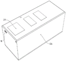
Fig. 1 is a schematic overall structure diagram of the present invention;
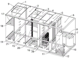
FIG. 2 is an overall internal structure view of the present invention;
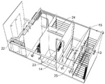
FIG. 3 is an overall internal side view of the present invention;
FIG. 4 is a second overall view structural diagram of the present invention;
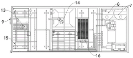
fig. 5 is a plan view of the whole of the present invention.
In the figure: 1. an anoxic tank; 2. an aerobic tank; 3. a sedimentation tank; 4. an aeration tank; 5. a membrane tank; 6. a device room; 7. a medicine washing water tank; 8. a backwash water tank; 9. a water inlet; 10. a self-priming pump; 11. a control cabinet; 12. a Roots blower; 13. an anoxic circulation pump; 14. a sludge reflux pump; 15. a microporous aerator; 16. an MBR membrane module; 17. a combined filler fixing bracket; 18. combining filler and lacing wire; 19. an aeration pipe fixing bracket; 20. combining fillers; 21. climbing a ladder; 22. a water producing port; 23. a second communicating pipe; 24. a first connecting through groove; 25. a first communication pipe; 26. a housing; 27. an inlet; 28. the second is connected the logical groove.
Detailed Description
The technical solutions in the embodiments of the present invention will be described clearly and completely with reference to the accompanying drawings in the embodiments of the present invention, and it is obvious that the described embodiments are only some embodiments of the present invention, not all embodiments.
Referring to fig. 1-5, the integrated intelligent domestic sewage treatment device comprises a housing 26, a water inlet 9 is formed in one side of the housing 26, sewage is conveyed to the water inlet 9 through a water pump, an electromagnetic flowmeter and an electric ball valve are arranged at the water inlet 9, the water inlet flow to be controlled is set through an internal program of a control cabinet 11, namely, the size of the valve is adjusted through the electric ball valve, and the water inlet flow is controlled.
Further, an anoxic tank 1, an aerobic tank 2, a sedimentation tank 3, an aeration tank 4, a membrane tank 5 and an equipment room 6 are sequentially arranged on the inner side of the shell 26;
specifically, the bottom ends of the anoxic tank 1, the aerobic tank 2, the aeration tank 4 and the membrane tank 5 are respectively fixed with an aeration pipe fixing support 19, the upper end of the aeration pipe fixing support 19 is fixed with a microporous aerator 15, the upper end of the aeration pipe fixing support is matched with the microporous aerator 15, a Roots blower 12 is also arranged at the inner side of the equipment room 6, and the Roots blower 12 is respectively connected with the microporous aerators 15 at the inner sides of the anoxic tank 1, the aerobic tank 2, the aeration tank 4 and the membrane tank 5 through multi-way pipes;
by opening the roots blower 12, the roots blower 12 aerates the inner sides of the anoxic tank 1, the aerobic tank 2, the aeration tank 4 and the membrane tank 5, so that the microporous aerators 15 positioned at the inner sides of the anoxic tank 1, the aerobic tank 2, the aeration tank 4 and the membrane tank 5 start to work simultaneously to generate a large amount of micro bubbles.
Further, a combined filler fixing support 17 is fixed on the inner wall of the anoxic tank 1, a combined filler lacing wire 18 is fixed on the inner side of the combined filler fixing support 17, the combined filler lacing wire 18 is used for fixing a combined filler 20, sewage can be preliminarily cleaned by arranging the combined filler 20, an anoxic circulating pump 13 is further fixed inside the anoxic tank 1, and the anoxic circulating pump 13 is used for conveying the sewage at the upper part inside the anoxic tank 1 to the bottom;
specifically, the input of oxygen deficiency circulating pump 13 is located the inside upper end in oxygen deficiency pond 1, and the output of oxygen deficiency circulating pump 13 is located the inside bottom in oxygen deficiency pond 1 for the sewage of oxygen deficiency pond 1 upper end passes through oxygen deficiency circulating pump 13 and carries the bottom in oxygen deficiency pond 1.
The sewage at the upper part of the anoxic tank 1 is conveyed to the bottom by the anoxic circulating pump 13, so that the aim of sewage circulation is fulfilled, and the contact time between the sewage and the combined filler 20 is prolonged.
Further, oxygen deficiency pond 1 and good oxygen pond 2 carry out through connection through first communicating pipe 25, the one end of first communicating pipe 25 is located the upper end of 1 inner wall in oxygen deficiency pond, the other end of first communicating pipe 25 is located the bottom of good oxygen pond 2, make 1 inside through the sewage of processing in oxygen deficiency pond enter into the bottom in good oxygen pond 2 through first communicating pipe 25, be equipped with micropore aerator 15 through the bottom at good oxygen pond 2, utilize roots's fan 12 to aerate it, increase the oxygen content in the sewage, then utilize the microorganism of production in the sewage, organic matter to in the sewage degrades.
Further, good oxygen pond 2 carries out through connection through second communicating pipe 23 and sedimentation tank 3, and the one end that the second communicated pipe 23 is located the upper end of good oxygen pond 2 inner walls, and the other end that the second communicated pipe 23 is located the bottom of sedimentation tank 3 for sewage flows to 3 bottoms of sedimentation tank through second communicating pipe 23 from good oxygen pond 2 upper ends, then through the action of gravity, deposits mud.
Further, the inside of sedimentation tank 3 still is fixed with mud backwash pump 14 for in carrying mud back to good oxygen pond 2, specifically, the input of mud backwash pump 14 is located the inside bottom of sedimentation tank 3, and the output of mud backwash pump 14 is located the inside bottom in good oxygen pond 2.
The sludge reflux pump 14 is opened, so that the sludge in the sedimentation tank 3 is conveyed back to the bottom end of the aerobic tank 2, and the clear liquid at the upper end of the sedimentation tank 3 flows into the aeration tank 4 through the first connecting through groove 24;
specifically, the sedimentation tank 3 and the aeration tank 4 are communicated through a first connecting through groove 24, a plurality of combined fillers 20 are fixed inside the aeration tank 4, the aeration tank 4 and the membrane tank 5 are communicated through a second connecting through groove 28, the first connecting through groove 24 is arranged at the upper end inside the aeration tank 4, and the second connecting through groove 28 is arranged at the bottom end of the inner wall of the membrane tank 5;
the water is fed from the upper end of the aeration tank 4, the water is discharged from the bottom, and the composite filler 20 is fixed in the middle, so that the biological bacteria can be effectively solidified.
At the inside of membrane cisterna 5 be fixed with MBR membrane module 16, self priming pump 10 in addition, self priming pump 10 is used for producing the negative pressure to MBR membrane module 16, draws out water, and the output of self priming pump 10 is connected with produces mouth of a river 22, and the surface of producing mouth of a river 22 is provided with electromagnetic flowmeter.
The water is pumped out by the MBR membrane module 16 by utilizing the negative pressure of the self-priming pump 10 and is discharged by the water production port 22 after reaching the standard.
Further, self priming pump 10 has two, connect through many siphunculuss between the self priming pump 10, one of them self priming pump 10 is used for reserve, when another self priming pump 10 breaks down, can start reserve self priming pump 10, self priming pump 10 still has backwash water tank 8 and medicine washing water tank 7 through many siphunculuss connection, when the device moves an end time, through the program of 11 inside settings of switch board, carry water to membrane cisterna 5 from backwash water tank 8 and carry out the backwash automatically, when MBR 16 blocks up, when detecting the outlet speed of producing mouth of a river 22 and reducing the critical value that the inside program set up, carry the medicine from medicine washing water tank 7 to membrane cisterna 5 automatically and wash, realize unmanned on duty full automatic control operation.
And the control cabinet 11, the control cabinet 11 respectively with roots's fan 12, self priming pump 10, electromagnetic flowmeter, electronic ball valve, oxygen deficiency circulating pump 13 and sludge reflux pump 14 electric connection, make the device realize the automation through preset's procedure.
The control cabinet 11, the Roots blower 12, the medicine washing water tank 7 and the backwashing water tank 8 are positioned on the inner side of the equipment room 6.
Preferably, in order to clean the inside of the housing 26, the inner walls of the anoxic tank 1, the aerobic tank 2, the aeration tank 4 and the membrane tank 5 are respectively fixed with a ladder stand 21, and the upper end of the housing 26 is provided with a plurality of inlets 27, so that when the inside of the device is cleaned integrally, the inside can be accessed through the ladder stand 21 by opening the inlets 27, and the cleaning can be conveniently performed.
By integrating a plurality of sewage treatment mechanisms in one device, a secondary sedimentation tank is not required to be built, the construction cost and the floor area of the integrated treatment system are reduced, the secondary sedimentation tank is not required to be added, the operation and maintenance burden is reduced, and the equipment cost of the system is reduced; the content of suspended matters in produced water is reduced, and the quality of the effluent is stable;
through the integrated design, the device is simple to disassemble and install and occupies small area;
and different specifications can be manufactured according to different working conditions, and the device is suitable for domestic wastewater in different regions.
It is obvious to a person skilled in the art that the invention is not restricted to details of the above-described exemplary embodiments, but that it can be implemented in other specific forms without departing from the spirit or essential characteristics of the invention. The present embodiments are therefore to be considered in all respects as illustrative and not restrictive, the scope of the invention being indicated by the appended claims rather than by the foregoing description, and all changes which come within the meaning and range of equivalency of the claims are therefore intended to be embraced therein. Any reference sign in a claim should not be construed as limiting the claim concerned.
Claims (10)
1. Intelligent sewage treatment plant of integral type, including shell (26), its characterized in that: a water inlet (9) is formed in one side of the shell (26), and an anoxic tank (1), an aerobic tank (2), a sedimentation tank (3), an aeration tank (4), a membrane tank (5) and an equipment room (6) are sequentially arranged in the inner side of the shell (26); the bottom ends of the anoxic tank (1), the aerobic tank (2), the aeration tank (4) and the membrane tank (5) are respectively fixed with an aeration pipe fixing support (19), and the upper end of the aeration pipe fixing support (19) is fixed with a microporous aerator (15); a Roots blower (12) is also arranged at the inner side of the equipment room (6), and the Roots blower (12) is respectively connected with the anoxic tank (1), the aerobic tank (2), the aeration tank (4) and the microporous aerator (15) at the inner side of the membrane tank (5) through multi-way pipes; a combined filler fixing support (17) is fixed on the inner wall of the anoxic tank (1), a combined filler lacing wire (18) is fixed on the inner side of the combined filler fixing support (17), and the combined filler lacing wire (18) is used for fixing a combined filler (20); the anoxic tank (1) is communicated with the aerobic tank (2) through a first communicating pipe (25), and the aerobic tank (2) is communicated with the sedimentation tank (3) through a second communicating pipe (23); a sludge return pump (14) is fixed in the sedimentation tank (3) and used for conveying sludge back to the aerobic tank (2); the sedimentation tank (3) is communicated with the aeration tank (4) through a first connecting through groove (24), and a plurality of combined fillers (20) are fixed inside the aeration tank (4); the aeration tank (4) is communicated with the membrane tank (5) through a second connecting through groove (28), and an MBR membrane module (16) is fixed inside the membrane tank (5); and the self-priming pump (10) is used for generating negative pressure on the MBR membrane module (16) and pumping water out, and the output end of the self-priming pump (10) is connected with a water generating port (22).
2. The integrated intelligent domestic sewage treatment device according to claim 1, wherein: the inside in oxygen deficiency pond (1) still is fixed with oxygen deficiency circulating pump (13), oxygen deficiency circulating pump (13) are used for carrying the sewage of upper portion to the bottom in oxygen deficiency pond (1).
3. The integrated intelligent domestic sewage treatment device according to claim 2, wherein: the inner walls of the anoxic tank (1), the aerobic tank (2), the aeration tank (4) and the membrane tank (5) are all fixed with a ladder stand (21), and the upper end of the shell (26) is provided with a plurality of inlets (27).
4. The integrated intelligent domestic sewage treatment device according to claim 3, wherein: the input of oxygen deficiency circulating pump (13) is located the inside upper end in oxygen deficiency pond (1), the output of oxygen deficiency circulating pump (13) is located the inside bottom in oxygen deficiency pond (1).
5. The integrated intelligent domestic sewage treatment device according to claim 4, wherein: the input end of the sludge reflux pump (14) is positioned at the bottom end inside the sedimentation tank (3), and the output end of the sludge reflux pump (14) is positioned at the bottom end inside the aerobic tank (2).
6. The integrated intelligent domestic sewage treatment apparatus according to claim 5, wherein: the automatic medicine washing device is characterized in that the number of the self-sucking pumps (10) is two, the self-sucking pumps (10) are connected through multi-way pipes, and the self-sucking pumps (10) are further connected with a backwashing water tank (8) and a medicine washing water tank (7) through the multi-way pipes.
7. The integrated intelligent domestic sewage treatment device according to claim 6, wherein: one end of the first communicating pipe (25) is positioned at the upper end of the inner wall of the anoxic tank (1), and the other end of the first communicating pipe (25) is positioned at the bottom end of the aerobic tank (2).
8. The integrated intelligent domestic sewage treatment apparatus according to claim 7, wherein: one end of the second communicating pipe (23) is positioned at the upper end of the inner wall of the aerobic tank (2), and the other end of the second communicating pipe (23) is positioned at the bottom end of the sedimentation tank (3).
9. The integrated intelligent domestic sewage treatment device according to claim 8, wherein: the first connecting through groove (24) is arranged at the upper end inside the aeration tank (4), and the second connecting through groove (28) is arranged at the bottom end of the inner wall of the membrane tank (5).
10. The integrated intelligent domestic sewage treatment device according to claim 9, wherein: and the control cabinet (11) is also arranged, and the control cabinet (11) is respectively and electrically connected with the Roots blower (12), the self-priming pump (10), the anoxic circulating pump (13) and the sludge reflux pump (14).
Priority Applications (1)
| Application Number | Priority Date | Filing Date | Title |
|---|---|---|---|
| CN202220099412.5U CN217077286U (en) | 2022-01-15 | 2022-01-15 | Integrated intelligent domestic sewage treatment device |
Applications Claiming Priority (1)
| Application Number | Priority Date | Filing Date | Title |
|---|---|---|---|
| CN202220099412.5U CN217077286U (en) | 2022-01-15 | 2022-01-15 | Integrated intelligent domestic sewage treatment device |
Publications (1)
| Publication Number | Publication Date |
|---|---|
| CN217077286U true CN217077286U (en) | 2022-07-29 |
Family
ID=82541853
Family Applications (1)
| Application Number | Title | Priority Date | Filing Date |
|---|---|---|---|
| CN202220099412.5U Active CN217077286U (en) | 2022-01-15 | 2022-01-15 | Integrated intelligent domestic sewage treatment device |
Country Status (1)
| Country | Link |
|---|---|
| CN (1) | CN217077286U (en) |
-
2022
- 2022-01-15 CN CN202220099412.5U patent/CN217077286U/en active Active
Similar Documents
| Publication | Publication Date | Title |
|---|---|---|
| CN209635975U (en) | Integrated continuous operation intensified denitrification and dephosphorization MBR membrane bioreactor equipment | |
| KR200385782Y1 (en) | high concentration sludge collector and mixing apparatus | |
| CN217077286U (en) | Integrated intelligent domestic sewage treatment device | |
| CN100526230C (en) | Diaphragm type oxygenate apparatus | |
| CN105541029A (en) | Unpowered backflow integrated reclaimed water reuse device | |
| CN216377819U (en) | Self-balancing integration MBR sewage treatment device | |
| CN211644769U (en) | MBR sewage treatment system | |
| CN206188491U (en) | Membrane bioreactor that sewage sludge integration was handled | |
| CN214270604U (en) | Single-power sewage treatment system and sewage treatment tank thereof | |
| CN201021441Y (en) | Film oxygen charging device | |
| CN209537092U (en) | Country sewage Intelligent treatment integrated apparatus | |
| CN110950434A (en) | MBR sewage treatment system and control method thereof | |
| CN216890314U (en) | Wastewater treatment system | |
| CN206109150U (en) | One -piece type sewage treatment unit of HBNA series | |
| CN206203982U (en) | A kind of new microbubble aerobe aeration tank | |
| JP3419257B2 (en) | Immersion membrane solid-liquid separator | |
| CN209940785U (en) | Novel domestic sewage integrated treatment device | |
| CN110627330A (en) | A textile printing and dyeing effluent treatment plant for reuse of reclaimed water | |
| CN209906444U (en) | Membrane siphon goes out water MBR device | |
| CN215102710U (en) | Sewage treatment device | |
| CN215327196U (en) | SBR improvement type integrated sewage equipment | |
| CN218539429U (en) | Land-saving unpowered internal reflux sewage treatment device | |
| CN211367131U (en) | Domestic sewage treatment equipment | |
| CN214060274U (en) | High-efficient sewage treatment biochemical system | |
| CN219518402U (en) | Automatic off-line medicine of MBR membrane module washes integration equipment |
Legal Events
| Date | Code | Title | Description |
|---|---|---|---|
| GR01 | Patent grant | ||
| GR01 | Patent grant | ||
| TR01 | Transfer of patent right |
Effective date of registration: 20240401 Address after: No.513, 5th floor, No.62 nongnong Road East, Jinshui District, Zhengzhou City, Henan Province, 450000 Patentee after: Guchuan Construction Group Co.,Ltd. Country or region after: China Address before: 201400 Room 309, building 9, phase I, excellence Century Center, Lane 1288, Wangyuan South Road, Fengxian District, Shanghai Patentee before: Wang Wei Country or region before: China |