CN217056825U - Rigid plugging device for leakage of pressurized fluid pipeline - Google Patents
Rigid plugging device for leakage of pressurized fluid pipeline Download PDFInfo
- Publication number
- CN217056825U CN217056825U CN202123033454.3U CN202123033454U CN217056825U CN 217056825 U CN217056825 U CN 217056825U CN 202123033454 U CN202123033454 U CN 202123033454U CN 217056825 U CN217056825 U CN 217056825U
- Authority
- CN
- China
- Prior art keywords
- pipeline
- groove
- pressurized fluid
- fluid pipeline
- cavity
- Prior art date
- Legal status (The legal status is an assumption and is not a legal conclusion. Google has not performed a legal analysis and makes no representation as to the accuracy of the status listed.)
- Active
Links
Images

Landscapes
- Pipeline Systems (AREA)
Abstract
The utility model provides a pressure fluid pipeline rigid plugging device for seepage, including its inner band cavity, its both ends take the casing of first pipeline recess, its characterized in that the casing is formed by the combination of two the same half shells, is equipped with the gland of its upper band second pipeline recess in the first pipeline recess at every half shell both ends, is equipped with in the second pipeline recess of gland and presses the sealing washer that fluid pipeline connects mutually to join in marriage with the pressure, and first pipeline recess outer end is equipped with first semicircular ring flange, is equipped with a plurality of first screws on this first semicircular ring flange. The two half shells can be quickly wrapped and fixed behind the leakage position of the pressurized fluid pipeline, the two ends of the shell are sealed through the gland and the sealing ring, the blocking of the leakage position of the pressurized fluid pipeline is completed, the pipeline does not need to be separated or welded, the operation is simple, the sealing effect is good, the working efficiency can be improved, the waste of resources can be reduced, and the working efficiency is high.
Description
Technical Field
The utility model relates to a piping installation technical field especially relates to a pressure fluid pipeline rigidity plugging device for seepage.
Background
The fluid medium is transported under pressure in a liquid medium transportation mode commonly used by traditional enterprises, and a fluid pipeline has a hollow section and is used for transporting oil, natural gas, coal gas, water and certain solid materials. At present, the pipeline connection of the pressurized fluid is mainly carried out through a flange plate and a threaded opening. In the prior art, after a pipeline connected with a threaded port leaks, a binding, isolating or manufacturing clamp is adopted to wrap a leakage point and establish a sealing cavity, so that the leakage part of the pipeline is sealed, but when a pipeline interface with fluid in the pipeline is sealed, a large amount of fluid is sprayed when the pipeline is separated for operation, so that the waste of resources is caused; in addition, when the sealing tape is directly wound on the outer side of the pipeline for plugging, firstly, the sealing effect is poor, and secondly, the aging is easy, so that the service life is influenced; the welding requires a special tool for operation, which is troublesome. Therefore, there is a need for improvements in the prior art.
SUMMERY OF THE UTILITY MODEL
An object of the utility model is to provide a pressure fluid pipeline rigidity plugging device for seepage, the device is sealed effectual, can improve work efficiency, can also reduce the waste of resource, convenient operation.
In order to achieve the above object, the utility model provides a following technical scheme: the rigid plugging device is characterized in that the shell is formed by combining two identical half shells, a gland with a second pipeline groove is arranged in the first pipeline groove at the two ends of each half shell, a sealing ring matched with the pressurized fluid pipeline is arranged in the second pipeline groove of the gland, a first semicircular flange plate is arranged at the outer end of the first pipeline groove, and a plurality of first screw holes are formed in the first semicircular flange plate so as to wrap and fix the two half shells at the leakage position of the pressurized fluid pipeline, then the two ends of the shell are sealed through the gland and the sealing ring, and the plugging of the leakage position of the pressurized fluid pipeline is completed.
The outer end of the gland is provided with a second semicircular flange plate, the second semicircular flange plate is provided with a plurality of second screw holes matched with the plurality of first screw holes in the first semicircular flange plate at the outer end of the first pipeline groove of the shell, and each second screw hole is internally provided with a screw or a bolt and a nut so that the gland can be fixed on the shell through the screw or the bolt and the nut.
A groove is symmetrically formed in one of the semi-rectangular body combination surfaces of the shell, a protrusion matched with the groove is symmetrically formed in the other semi-rectangular body combination surface of the shell, a corresponding sealing gasket is arranged in the groove, the groove and the protrusion are located on the outer side of the cavity, and therefore after the two semi-rectangular bodies are combined, the two semi-rectangular bodies are located through the groove and the protrusion which are arranged mutually and sealed through the sealing gasket.
The two half shells of the shell respectively comprise a cavity which is trapezoidal, the left end and the right end of the cavity are respectively provided with a first pipeline groove communicated with the cavity, the first pipeline groove is provided with a semi-cylindrical shape matched with the pressurized fluid pipeline, the front side and the rear side of the cavity are respectively provided with a rectangular flange, the rectangular flange is provided with a plurality of screw holes, and each screw hole is internally provided with a bolt and a nut, so that after the two half shells are wrapped on the pressurized fluid pipeline and folded, the two half shells are connected into a sealed whole through the screw holes on the rectangular flange and the bolts and nuts in the screw holes, and further the leakage part of the pressurized fluid pipeline is blocked.
Compared with the prior art, the utility model discloses following beneficial effect has: by adopting the technical scheme, the two half shells can be quickly wrapped and fixed behind the leakage part of the pressurized fluid pipeline, the two ends of the shell are sealed through the gland and the sealing ring, the blocking of the leakage part of the pressurized fluid pipeline is completed, the pipeline does not need to be separated or welded, the operation is simple, the sealing effect is good, the working efficiency can be improved, the waste of resources can be reduced, and the working efficiency is high.
Drawings
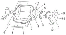
FIG. 1 is a schematic diagram of the explosion structure of the present invention;
fig. 2 is a schematic plan view of the present invention.
Detailed Description
The technical solutions in the embodiments of the present invention will be clearly and completely described below with reference to the accompanying drawings in the embodiments of the present invention, and it is obvious that the described embodiments are only some embodiments of the present invention, not all embodiments; based on the embodiments in the present invention, all other embodiments obtained by a person skilled in the art without creative work belong to the protection scope of the present invention.
Examples
Referring to fig. 1-2, the present invention provides a rigid plugging device for leakage of pressurized fluid pipeline, which comprises a housing 1 having a cavity 2 therein and first pipeline grooves 5 at two ends thereof, wherein: the casing 1 is formed by combining two identical half casings, a gland 6 with a second pipeline groove 61 is arranged in a first pipeline groove 5 at two ends of each half casing, a sealing ring 8 matched with the pressurized fluid pipeline A is arranged in a second pipeline groove 61 of the gland 6, a first semicircular flange 51 is arranged at the outer end of the first pipeline groove 5, and a plurality of first screw holes 7 are arranged on the first semicircular flange 51 so as to wrap and fix the two half casings at the leakage position of the pressurized fluid pipeline A and seal two ends of the casing 1 through the gland 6 and the sealing ring 8 to complete the plugging of the leakage position of the pressurized fluid pipeline A;
a second semicircular flange 63 is arranged at the outer end of the gland 6, a plurality of second screw holes 62 matched with the plurality of first screw holes 7 on the first semicircular flange 51 at the outer end of the first pipeline groove 5 of the shell 1 are arranged on the second semicircular flange 63, and a screw or a bolt and a nut are arranged in each second screw hole 62 so that the gland 6 can be fixed on the shell 1 through the screw or the bolt and the nut;
a groove 3 is symmetrically arranged on one semi-rectangular combined surface of the shell 1, a protrusion matched and connected with the groove 3 is symmetrically arranged on the other semi-rectangular combined surface, a corresponding sealing gasket (not shown) is arranged in the groove 3, and the groove 3 and the protrusion are both positioned outside the cavity 2, so that after the two semi-rectangular bodies are combined, the positioning is carried out through the mutually arranged groove 3 and protrusion, and then the sealing is carried out through the sealing gasket.
The two half shells of the shell 1 all comprise a cavity 2, the cavity 2 is trapezoidal, the left end and the right end of the cavity 2 are respectively provided with a first pipeline groove 5 communicated with the cavity 2, the first pipeline groove 5 is semi-cylindrical and matched with the pressurized fluid pipeline A, the front side and the rear side of the cavity 2 are respectively provided with a rectangular flange, the rectangular flange is provided with a plurality of screw holes 4, each screw hole 4 is internally provided with a bolt and a nut, so that the two half shells are wrapped on the pressurized fluid pipeline A and closed, and then connected into a sealed whole through the screw holes on the rectangular flange and the bolts and nuts in the screw holes, and further blocking the leakage part of the pressurized fluid pipeline A.
Although embodiments of the present invention have been shown and described, it will be appreciated by those skilled in the art that changes, modifications, substitutions and alterations can be made in these embodiments without departing from the principles and spirit of the invention, the scope of which is defined in the appended claims and their equivalents.
Claims (4)
1. The utility model provides a pressure fluid pipeline rigid plugging device for seepage, includes its interior tape cavity, its both ends take the casing of first pipeline recess, its characterized in that the casing is formed by the combination of same two half shells, is equipped with the gland of its area second pipeline recess in the first pipeline recess at every half shell both ends, is equipped with the sealing washer that matches with the pressure fluid pipeline in the second pipeline recess of gland, and first pipeline recess outer end is equipped with first semicircle ring flange, is equipped with a plurality of first screws on this first semicircle ring flange.
2. The rigid plugging device for leakage of a pressurized fluid pipeline according to claim 1, wherein: the outer end of the gland is provided with a second semicircular flange plate, the second semicircular flange plate is provided with a plurality of second screw holes matched with the first screw holes in the first semicircular flange plate at the outer end of the first pipeline groove of the shell, and each second screw hole is internally provided with a screw or a bolt and a nut.
3. The rigid plugging device for the leakage of the pressurized fluid pipeline according to claim 1, wherein the combination surface of one of the semi-rectangular bodies of the casing is symmetrically provided with a groove, the combination surface of the other semi-rectangular body is symmetrically provided with a protrusion matched and connected with the groove, the groove is internally provided with a corresponding sealing gasket, and the groove and the protrusion are both positioned outside the cavity.
4. A rigid blocking device for leakage from a pressurized fluid pipeline according to claim 1, wherein each of the two half shells of the housing comprises a trapezoidal cavity, the left and right ends of the cavity are respectively provided with a first pipeline groove communicated with the cavity, the first pipeline groove is provided with a semi-cylindrical shape matched with the pressurized fluid pipeline, the front and rear sides of the cavity are respectively provided with a rectangular flange, the rectangular flange is provided with a plurality of screw holes, and each screw hole is provided with a bolt and a nut.
Priority Applications (1)
| Application Number | Priority Date | Filing Date | Title |
|---|---|---|---|
| CN202123033454.3U CN217056825U (en) | 2021-12-06 | 2021-12-06 | Rigid plugging device for leakage of pressurized fluid pipeline |
Applications Claiming Priority (1)
| Application Number | Priority Date | Filing Date | Title |
|---|---|---|---|
| CN202123033454.3U CN217056825U (en) | 2021-12-06 | 2021-12-06 | Rigid plugging device for leakage of pressurized fluid pipeline |
Publications (1)
| Publication Number | Publication Date |
|---|---|
| CN217056825U true CN217056825U (en) | 2022-07-26 |
Family
ID=82476600
Family Applications (1)
| Application Number | Title | Priority Date | Filing Date |
|---|---|---|---|
| CN202123033454.3U Active CN217056825U (en) | 2021-12-06 | 2021-12-06 | Rigid plugging device for leakage of pressurized fluid pipeline |
Country Status (1)
| Country | Link |
|---|---|
| CN (1) | CN217056825U (en) |
-
2021
- 2021-12-06 CN CN202123033454.3U patent/CN217056825U/en active Active
Similar Documents
| Publication | Publication Date | Title |
|---|---|---|
| CN217056825U (en) | Rigid plugging device for leakage of pressurized fluid pipeline | |
| CN212319069U (en) | Double containment structure clamp formula flange | |
| CN209943736U (en) | High-pressure hydraulic pipe fitting sealing joint | |
| CN216843553U (en) | Gas power generation pipeline sealing connection device | |
| CN216955043U (en) | Small-bore flange junction gas tightness detection device | |
| CN215891562U (en) | Plugging device suitable for marine hose connector is used in test of suppressing | |
| CN213900310U (en) | Rotary CF blind flange plugging structure | |
| CN212361246U (en) | Plugging device | |
| CN213206855U (en) | Large-diameter reinforced concrete drain pipe connecting structure | |
| CN213512544U (en) | Anti-loosening steel pipe flange | |
| CN218863516U (en) | Convenient operation's pipe connection spare | |
| CN210800425U (en) | Pressure reducing valve applied to curved pipeline | |
| CN208703347U (en) | A kind of connection structure of tap water inlet pipe and water supplying pipe | |
| CN105546239A (en) | External connecting type buckle structure | |
| CN213744264U (en) | Wind power device oil leakage prevention plate with high sealing performance | |
| CN218326672U (en) | Leakage-proof device for tap water supply pipeline | |
| CN212298041U (en) | Flange with good sealing effect | |
| CN205534699U (en) | Circumscribed buckle structure | |
| CN203614974U (en) | Connector for quick connection of oil filter oil pipes | |
| CN221075600U (en) | Hydraulic part joint structure with sealing assembly | |
| CN221879713U (en) | High-sealing horizontal centrifugal pump | |
| CN220583698U (en) | Hydraulic test tool for narrow sealing surface booster shell | |
| CN212584467U (en) | EPDM pipeline sealing element | |
| CN217714070U (en) | Special quick repair joint for steel-plastic composite pipe | |
| CN212929094U (en) | Flange plate |
Legal Events
| Date | Code | Title | Description |
|---|---|---|---|
| GR01 | Patent grant | ||
| GR01 | Patent grant |