CN217019455U - High-precision flat tongs machine tool fixture - Google Patents
High-precision flat tongs machine tool fixture Download PDFInfo
- Publication number
- CN217019455U CN217019455U CN202123213567.1U CN202123213567U CN217019455U CN 217019455 U CN217019455 U CN 217019455U CN 202123213567 U CN202123213567 U CN 202123213567U CN 217019455 U CN217019455 U CN 217019455U
- Authority
- CN
- China
- Prior art keywords
- plate
- machine tool
- electric putter
- base
- placing
- Prior art date
- Legal status (The legal status is an assumption and is not a legal conclusion. Google has not performed a legal analysis and makes no representation as to the accuracy of the status listed.)
- Active
Links
Images
Landscapes
- Jigs For Machine Tools (AREA)
Abstract
The utility model discloses a high-precision flat tongs machine tool fixture which comprises a base, wherein a placing plate is rotatably connected to the base, a mounting groove is formed in the upper end of the base, a first electric push rod is mounted in the mounting groove, a sliding plate is mounted at the output end of the first electric push rod, a supporting plate is hinged between the sliding plate and the placing plate, a positioning block is mounted on the placing plate, a U-shaped plate is fixedly connected to the placing plate, two opposite guide grooves are formed in the inner wall of the U-shaped plate, rack plates are slidably connected to the two guide grooves, clamping columns are mounted at one ends of the two rack plates and one end of a second electric push rod, and a second electric push rod is mounted on the U-shaped plate. The clamping device not only can stably clamp workpieces with different height surfaces and has wide application range, but also can clamp plane workpieces, and simultaneously can accurately adjust the angles of the workpieces to improve the machining precision.
Description
Technical Field
The utility model relates to the technical field of clamps, in particular to a high-precision flat tongs machine tool clamp.
Background
The jig is a device for fixing a processing object to occupy a correct position for receiving construction or inspection in a machine manufacturing process.
Although the existing clamp can stably clamp workpieces, the workpieces with different clamping surfaces cannot be effectively treated; meanwhile, the prior art discloses a high-precision flat tongs machine tool clamp with the application number of CN201520337574.8, and the precision of the angle adjustment of the clamped workpiece is not high, and the improvement is needed.
Therefore, a high-precision flat tongs machine tool clamp is designed to solve the problems.
SUMMERY OF THE UTILITY MODEL
The utility model aims to solve the defects in the prior art and provides a high-precision flat tongs machine tool clamp.
In order to achieve the purpose, the utility model adopts the following technical scheme:
the utility model provides a high-accuracy flat-nose pliers machine tool fixture, includes the base, it places the board to rotate to be connected with on the base, the upper end of base is equipped with the mounting groove, install first electric putter in the mounting groove, the slide is installed to first electric putter's output, the slide with place between the board articulated be connected with the backup pad, place and install the locating piece on the board, place fixedly connected with U template on the board, the inner wall of U template is equipped with two relative guide ways, two equal sliding connection has rack board, two in the guide way the centre gripping post is all installed with second electric putter's one end to rack board, install second electric putter on the U template, second electric putter extends to in the U template, just the gear is installed to second electric putter's output, the gear meshes with two rack boards mutually.
Preferably, the front and back end of placing the board is installed the connecting block, two the connecting block passes through the axostylus axostyle and is connected with the base is articulated.
Preferably, the support plate is hinged with the upper end of the sliding plate, and the support plate is hinged with the bottom of the placing plate.
Preferably, the clamping column is fixedly connected with a rubber pad at one end opposite to the rack plate.
Preferably, the guide groove has a U-shape.
Preferably, the output end of the second electric push rod is provided with a mounting rack, and the gear is arranged on the mounting rack.
Compared with the prior art, the utility model has the beneficial effects that:
1. the work of second electric putter drives gear, two rack plates and two centre gripping post removals, and when one of them centre gripping post offseted with the eminence of work piece, along with second electric putter's removal for the rack plate that corresponds offsets with the work piece removes, thereby drive gear rotates, and another rack plate of gear drive removes, and then drives another centre gripping post and offset with the work piece, thereby can carry out stable centre gripping to the work piece, and can be applicable to the work piece of height difference, and application scope is wide.
2. First electric putter drive slide removes, under the backup pad effect, can drive places the board and rotates to the realization can carry out accurate regulation to the angle modulation of work piece through first electric putter to the angle of work piece.
In conclusion, the utility model can not only stably clamp workpieces with different height surfaces and has wide application range, but also clamp plane workpieces, and can accurately adjust the angle of the workpieces so as to improve the processing precision.
Drawings
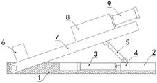
FIG. 1 is a schematic structural view of a high-precision flat tongs machine tool clamp provided by the utility model;
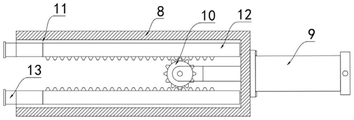
fig. 2 is a top view of a U-shaped plate in a high-precision flat tongs machine tool clamp.
In the figure: the clamping device comprises a base 1, a mounting groove 2, a first electric push rod 3, a sliding plate 4, a supporting plate 5, a positioning block 6, a placing plate 7, a U-shaped plate 8, a second electric push rod 9, a gear 10, a guide groove 11, a rack plate 12 and a clamping column 13.
Detailed Description
The technical solutions in the embodiments of the present invention will be clearly and completely described below with reference to the drawings in the embodiments of the present invention, and it is obvious that the described embodiments are only a part of the embodiments of the present invention, and not all of the embodiments.
Referring to fig. 1-2, the high-precision flat tongs machine tool clamp comprises a base 1, wherein a placing plate 7 is rotatably connected to the base 1, connecting blocks are mounted at the front end and the rear end of the placing plate 7, and the two connecting blocks are hinged to the base 1 through a shaft rod; the upper end of base 1 is equipped with mounting groove 2, installs first electric putter 3 in the mounting groove 2, and slide 4 is installed to first electric putter 3's output, and slide 4 and place articulated backup pad 5 that is connected with between the board 7, backup pad 5 and the articulated connection in upper end of slide 4, backup pad 5 and the articulated connection in bottom of placing board 7.
The positioning block 6 is installed on the placing plate 7, the U-shaped plate 8 is fixedly connected to the placing plate 7, two opposite guide grooves 11 are formed in the inner wall of the U-shaped plate 8, rack plates 12 are connected to the two guide grooves 11 in a sliding mode, and the guide grooves 11 are in a U-shaped shape, so that the rack plates 12 can slide stably; the clamping columns 13 are arranged at one ends of the two rack plates 12 and the second electric push rod 9, and the clamping columns 13 are fixedly connected with rubber pads at the ends back to the rack plates 12, so that a workpiece can be protected.
Install second electric putter 9 on the U-shaped board 8, in second electric putter 9 extended to U-shaped board 8, and gear 10 is installed to second electric putter 9's output, and the mounting bracket is installed to second electric putter 9's output, and gear 10 installs on the mounting bracket, and gear 10 meshes with two rack plates 12 mutually.
When the clamping device is used, a workpiece is abutted to the positioning block 6, then the second electric push rod 9 is started, the second electric push rod 9 works to drive the gear 10, the two rack plates 12 and the two clamping columns 13 to move, when one clamping column 13 is abutted to the high position of the workpiece, the rack plate 12 corresponding to the workpiece is moved along with the movement of the second electric push rod 9, so that the gear 10 is driven to rotate, the gear 10 drives the other rack plate 12 to move in a transmission manner, and the other clamping column 13 is driven to abut to the workpiece, so that the workpiece can be stably clamped, the clamping device can be suitable for workpieces with different heights and different surfaces, and the application range is wide;
when the angle adjustment is carried out to the work piece to needs, start 3 drive slides 4 removals of electric putter, under backup pad 5 effects, can drive and place board 7 and rotate to the realization can carry out accurate regulation to the angle adjustment of work piece, can carry out accurate regulation to the angle of work piece through electric putter 13.
The above description is only for the preferred embodiment of the present invention, but the scope of the present invention is not limited thereto, and any person skilled in the art should be considered to be within the technical scope of the present invention, and equivalent alternatives or modifications according to the technical solution of the present invention and the inventive concept thereof should be covered by the scope of the present invention.
Claims (6)
1. The utility model provides a high-accuracy flat-nose pliers machine tool fixture, includes base (1), its characterized in that, rotate on base (1) and be connected with and place board (7), the upper end of base (1) is equipped with mounting groove (2), install first electric putter (3) in mounting groove (2), slide (4) are installed to the output of first electric putter (3), articulated between slide (4) and the board of placing (7) are connected with backup pad (5), install locating piece (6) on placing board (7), fixedly connected with U template (8) on placing board (7), the inner wall of U template (8) is equipped with two relative guide ways (11), two equal sliding connection has rack plate (12) in guide way (11), two centre gripping post (13) are all installed to the one end of rack plate (12) and second electric putter (9), install second electric putter (9) on U template (8), second electric putter (9) extend to in U template (8), just gear (10) are installed to the output of second electric putter (9), gear (10) and two rack plates (12) mesh mutually.
2. A high-precision flat-nose pliers machine tool clamp as claimed in claim 1, characterized in that the front and back ends of the placing plate (7) are provided with connecting blocks, and the two connecting blocks are hinged with the base (1) through a shaft rod.
3. A high precision flat nose pliers machine tool clamp according to claim 1, characterized in that the support plate (5) is hinged with the upper end of the sliding plate (4), the support plate (5) is hinged with the bottom of the placing plate (7).
4. The high-precision flat tongs machine tool clamp according to claim 1, characterized in that a rubber pad is fixedly connected to the end of the clamping column (13) opposite to the rack plate (12).
5. A high precision flat nose pliers machine tool clamp according to claim 1, characterized in that the guide groove (11) is U-shaped.
6. A high precision flat nose pliers machine tool clamp according to claim 1, characterized in that the output of the second electric push rod (9) is mounted with a mounting bracket, on which the gear (10) is mounted.
Priority Applications (1)
| Application Number | Priority Date | Filing Date | Title |
|---|---|---|---|
| CN202123213567.1U CN217019455U (en) | 2021-12-20 | 2021-12-20 | High-precision flat tongs machine tool fixture |
Applications Claiming Priority (1)
| Application Number | Priority Date | Filing Date | Title |
|---|---|---|---|
| CN202123213567.1U CN217019455U (en) | 2021-12-20 | 2021-12-20 | High-precision flat tongs machine tool fixture |
Publications (1)
| Publication Number | Publication Date |
|---|---|
| CN217019455U true CN217019455U (en) | 2022-07-22 |
Family
ID=82442873
Family Applications (1)
| Application Number | Title | Priority Date | Filing Date |
|---|---|---|---|
| CN202123213567.1U Active CN217019455U (en) | 2021-12-20 | 2021-12-20 | High-precision flat tongs machine tool fixture |
Country Status (1)
| Country | Link |
|---|---|
| CN (1) | CN217019455U (en) |
-
2021
- 2021-12-20 CN CN202123213567.1U patent/CN217019455U/en active Active
Similar Documents
| Publication | Publication Date | Title |
|---|---|---|
| CN211029331U (en) | Chamfer edging device is used in processing of environmental protection alloy stick | |
| CN111872717A (en) | Anchor clamps for numerical control machining | |
| CN104999301A (en) | Machine tool machining center with clamp special for long-bar-shaped workpiece | |
| CN213946366U (en) | Anchor clamps with angle modulation function | |
| CN214081085U (en) | Anchor clamps for machine-building | |
| CN111975684B (en) | Clamp for repeatedly positioning workpieces | |
| CN214722323U (en) | Improved part tool positioning clamp | |
| CN217019455U (en) | High-precision flat tongs machine tool fixture | |
| CN211387843U (en) | Clamp structure for CNC (computer numerical control) machining | |
| CN218575548U (en) | Quick positioning and fixing clamp for machine manufacturing | |
| CN212445081U (en) | Stator processing is with adjusting frock | |
| CN213289480U (en) | Positioning device for machined part | |
| CN213731389U (en) | Workpiece positioning device for electric automation processing | |
| CN220944211U (en) | Clamp for numerical control machine tool | |
| CN221435727U (en) | Fixing tool for photovoltaic module bracket machining | |
| CN220761758U (en) | Lying clamp suitable for machining large workpiece | |
| CN221474232U (en) | Clamping device for machine tool | |
| CN221538915U (en) | Numerical control machine tool machining diagonal bracing clamp capable of being finely adjusted | |
| CN219788274U (en) | Workpiece clamping device | |
| CN217372013U (en) | High-precision instrument clamp | |
| CN216940215U (en) | Machining device | |
| CN220783855U (en) | Tool clamp capable of protecting workpiece | |
| CN221755501U (en) | Machine tool fixture convenient for loading and unloading | |
| CN221676448U (en) | Multi-station clamping tool | |
| CN218284583U (en) | Machining center high accuracy adjustment subassembly |
Legal Events
| Date | Code | Title | Description |
|---|---|---|---|
| GR01 | Patent grant | ||
| GR01 | Patent grant |