CN216999941U - Landscape circulating water filters recycling apparatus - Google Patents
Landscape circulating water filters recycling apparatus Download PDFInfo
- Publication number
- CN216999941U CN216999941U CN202122476349.0U CN202122476349U CN216999941U CN 216999941 U CN216999941 U CN 216999941U CN 202122476349 U CN202122476349 U CN 202122476349U CN 216999941 U CN216999941 U CN 216999941U
- Authority
- CN
- China
- Prior art keywords
- wall
- water
- movable block
- collecting vessel
- filter screen
- Prior art date
- Legal status (The legal status is an assumption and is not a legal conclusion. Google has not performed a legal analysis and makes no representation as to the accuracy of the status listed.)
- Active
Links
Images

Abstract
The utility model discloses a device for filtering and recycling garden landscape circulating water, and belongs to the technical field of garden landscapes. The utility model provides a landscape circulating water filters recycling apparatus, includes the collecting vessel, its characterized in that: the collecting vessel upper end is equipped with the funnel, and the collecting vessel upper end is equipped with the filter screen, and the filter screen upper end is equipped with the axis of rotation, and the axis of rotation upper end is equipped with the impeller, and the inside upper end one side of collecting vessel articulates there is the closing plate, and the closing plate upper end has set firmly sealed the pad, and the activity inslot portion is equipped with the movable block, and the movable block outer wall is equipped with a plurality of water pipes, and collecting vessel outer wall left end is equipped with the bolt. According to the utility model, the water in the collecting barrel can flow out from different water outlets when the movable block (15) is rotated through arranging the plurality of water outlets, so that the water outlet amount can be conveniently controlled by workers according to different plant habits, the plants can be protected, and the water can be saved.
Description
Technical Field
The utility model relates to the technical field of landscape architecture, in particular to a device for filtering and recycling circulating water of landscape architecture.
Background
The lack of water resources has become a worldwide problem, needs to use a large amount of water resources when irrigating in gardens, wherein in rainy day, have a large amount of rainwater to flow away and lead to water waste, can not irrigate trees in the arid period that the water resource lacked. Traditional rainwater collection device is after collecting the rainwater, and the staff is difficult to master the water consumption according to the plant habit difference when using, easily leads to the water consumption too much or too little, not only can cause water waste, easily leads to the plant to die moreover or the water consumption is not enough to influence the plant normal growth. In view of this, we propose a landscape circulating water filtration recycles device.
SUMMERY OF THE UTILITY MODEL
1. Technical problem to be solved
The utility model aims to provide a device for filtering and recycling landscape circulating water so as to solve the problems in the background technology.
2. Technical scheme
The utility model provides a landscape circulating water filters recycling device, includes the collecting vessel, the collecting vessel upper end is equipped with the funnel, the collecting vessel upper end is equipped with the filter screen, the filter screen upper end is equipped with the axis of rotation, the axis of rotation upper end is equipped with the impeller, axis of rotation downside outer wall has set firmly the scraper blade, the inside upper end one side of collecting vessel articulates there is the closing plate, the closing plate upper end has set firmly sealed the pad, the closing plate lower extreme has set firmly the float, collecting vessel inner wall one end has set firmly the dog, the collecting vessel right-hand member runs through and is equipped with the fixture block, fixture block one end has set firmly the spring, a plurality of delivery ports have been seted up to collecting vessel inner wall left end, the activity groove has been seted up to collecting vessel outer wall left end, the inside movable block that is equipped with of activity groove, the movable block outer wall is equipped with a plurality of water pipes, collecting vessel outer wall left end is equipped with the bolt.
Preferably, the lower end of the rotating shaft is limited at the upper end of the filter screen and is rotationally connected with the filter screen, and the lower end of the scraper is in sliding contact with the upper end of the filter screen.
Preferably, the upper end of the stop block is connected with the lower end of the right side of the sealing plate, one side of the lower end of the clamping block is of an inclined structure, and one side of the right end of the sealing plate is in extrusion contact with one side of the lower end of the clamping block.
Preferably, the bolt end runs through the collecting vessel outer wall and with movable block outer wall extrusion contact, movable block upper and lower both sides outer wall and activity inslot wall sliding contact.
Preferably, the water pipe end runs through the movable block left end and communicates with the delivery port, and a plurality of the water pipe is the slope form setting.
3. Advantageous effects
Compared with the prior art, the utility model has the advantages that:
1. according to the utility model, the water outlets are arranged, so that the water pipes on the movable block can correspond to different water outlets respectively, so that water in the collecting barrel can flow out from different water outlets, and further, the water outlet quantity can be controlled by workers according to different plant habits, the plants can be protected, and meanwhile, the water can be saved.
2. According to the utility model, the impeller is arranged to clean leaves and sundries on the filter screen when the scraper is driven to rotate, so that blockage is avoided, the upper end of the collecting barrel can be automatically blocked when the collecting barrel is full of water through the arranged buoy, and waste caused by water loss is avoided.
Drawings
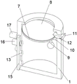
FIG. 1 is a schematic view of the overall structure of the present invention;
FIG. 2 is a schematic view of a seal plate portion structure of the present invention;
the numbering in the figures illustrates: 1. a collection barrel; 2. a funnel; 3. filtering with a screen; 4. a rotating shaft; 5. an impeller; 6. a squeegee; 7. a sealing plate; 8. a gasket; 9. floating; 10. a stopper; 11. a clamping block; 12. a spring; 13. a water outlet; 14. a movable groove; 15. a movable block; 16. a water pipe; 17. and (4) bolts.
Detailed Description
In the description of the present invention, it is to be understood that the terms "center", "longitudinal", "lateral", "length", "width", "thickness", "upper", "lower", "front", "rear", "left", "right", "vertical", "horizontal", "top", "bottom", "inner", "outer", "clockwise", "counterclockwise", and the like, indicate orientations and positional relationships based on those shown in the drawings, and are used only for convenience of description and simplicity of description, and do not indicate or imply that the equipment or element being referred to must have a particular orientation, be constructed and operated in a particular orientation, and thus, should not be considered as limiting the present invention.
In the description of the present invention, "a plurality" means two or more unless specifically defined otherwise.
In the description of the present invention, it should be noted that, unless otherwise explicitly specified or limited, the terms "mounted", "provided", "fitted/connected", "connected", and the like, are to be interpreted broadly, such as "connected", which may be fixedly connected, detachably connected, or integrally connected; can be mechanically or electrically connected; they may be connected directly or indirectly through intervening media, or they may be interconnected between two elements. The specific meanings of the above terms in the present invention can be understood in a specific case to those of ordinary skill in the art.
Referring to fig. 1-2, the present invention provides a technical solution:
the utility model provides a landscape circulating water filters device of recycling, including collecting vessel 1, 1 upper end of collecting vessel is equipped with funnel 2, 1 upper end of collecting vessel is equipped with filter screen 3, filter screen 3 upper end is equipped with axis of rotation 4, 4 upper ends of axis of rotation are equipped with impeller 5, 4 downside outer walls in axis of rotation have set firmly scraper blade 6, 1 inside upper end one side of collecting vessel articulates there is closing plate 7, the closing plate 7 upper end has set firmly sealed pad 8, 7 lower extremes of closing plate have set firmly cursory 9, 1 inner wall one end of collecting vessel has set firmly dog 10, 1 right-hand member of collecting vessel runs through and is equipped with fixture block 11, fixture block 11 one end has set firmly spring 12, a plurality of delivery ports 13 have been seted up to 1 inner wall left end of collecting vessel, movable groove 14 has been seted up to 1 outer wall left end of collecting vessel, the inside movable block 15 that is equipped with of movable block, 15 outer wall is equipped with a plurality of water pipes 16, 1 outer wall left end of collecting vessel is equipped with bolt 17.
Specifically, the lower end of the rotating shaft 4 is limited at the upper end of the filter screen 3 and is rotatably connected with the filter screen, and the lower end of the scraper 6 is in sliding contact with the upper end of the filter screen 3. The scraper 6 can clear up leaf and debris on the filter screen 3 after rotating, avoids causing the jam.
Furthermore, the upper end of the stopper 10 is connected with the lower end of the right side of the sealing plate 7, one side of the lower end of the clamping block 11 is in an inclined structure, and one side of the right end of the sealing plate 7 is in extrusion contact with one side of the lower end of the clamping block 11. Can extrude the fixture block 11 when sealing plate 7 rises and make the fixture block 11 shrink, later the fixture block 11 can be fixed sealing plate 7 under the effect of spring 12 to can plug up collecting vessel 1 upper end voluntarily, avoid moisture to run off.
Further, the tail end of the bolt 17 penetrates through the outer wall of the collecting barrel 1 and is in extrusion contact with the outer wall of the movable block 15, and the outer walls of the upper side and the lower side of the movable block 15 are in sliding contact with the inner wall of the movable groove 14. The movable block 15 can be fixed by the provided bolt 17.
Furthermore, the end of the water pipe 16 penetrates through the left end of the movable block 15 and is communicated with the water outlet 13, and the plurality of water pipes 16 are arranged in an inclined shape. The water pipes 16 on the movable block 15 correspond to different water outlets 13 respectively, so that water in the collecting barrel 1 can flow out from different water outlets 13, and the water outlet amount can be controlled by the staff conveniently according to plant habits.
The working principle is as follows: when the device is required to work, rainwater can flow into the collecting barrel 1 through the filter screen 3 through the funnel 2 in rainy days, when the rainwater impacts the impeller 5, the impeller 5 can be rotated, so that the scraper 6 rotates, leaves and sundries on the filter screen 3 can be cleaned after the scraper 6 rotates, and blockage is avoided, wherein when the water level in the collecting barrel 1 rises, the water can enable the buoy 9 to rise, the buoy 9 rises to enable the sealing plate 7 and the sealing gasket 8 to rise, the clamping block 11 can be extruded when the sealing plate 7 rises to enable the clamping block 11 to shrink, then the clamping block 11 can fix the sealing plate 7 under the action of the spring 12, so that the upper end of the collecting barrel 1 can be automatically blocked, and the water loss is avoided, when the movable block 15 is rotated through the plurality of water outlets 13, the plurality of water pipes 16 on the movable block 15 correspond to the different water outlets 13 respectively, so that the water in the collecting barrel 1 can flow out of the different water outlets 13, and then be convenient for the staff according to the different control water yield of plant habit, can the using water wisely when protecting the plant, can be fixed with movable block 15 through the bolt 17 that sets up.
The foregoing shows and describes the general principles, principal features, and advantages of the utility model. It should be understood by those skilled in the art that the present invention is not limited to the above embodiments, and the above embodiments and descriptions are only preferred examples of the present invention and are not intended to limit the present invention, and that various changes and modifications may be made without departing from the spirit and scope of the present invention, which fall within the scope of the claimed invention. The scope of the utility model is defined by the appended claims and equivalents thereof.
Claims (5)
1. The utility model provides a landscape circulating water filters recycling apparatus, includes collecting vessel (1), its characterized in that: the improved garbage collection device is characterized in that a funnel (2) is arranged at the upper end of a collection barrel (1), a filter screen (3) is arranged at the upper end of the collection barrel (1), a rotating shaft (4) is arranged at the upper end of the filter screen (3), an impeller (5) is arranged at the upper end of the rotating shaft (4), a scraper (6) is fixedly arranged on the outer wall of the lower side of the rotating shaft (4), a sealing plate (7) is hinged to one side of the upper end inside the collection barrel (1), a sealing gasket (8) is fixedly arranged at the upper end of the sealing plate (7), a buoy (9) is fixedly arranged at the lower end of the sealing plate (7), a stop block (10) is fixedly arranged at one end of the inner wall of the collection barrel (1), a clamping block (11) penetrates through the right end of the collection barrel (1), a spring (12) is fixedly arranged at one end of the clamping block (11), a plurality of water outlets (13) are formed at the left end of the inner wall of the collection barrel (1), a movable groove (14) is formed at the left end of the outer wall of the collection barrel (1), the improved garbage collection device is characterized in that a movable block (15) is arranged inside the movable groove (14), a plurality of water pipes (16) are arranged on the outer wall of the movable block (15), and a bolt (17) is arranged at the left end of the outer wall of the collection barrel (1).
2. The landscape circulating water filtering and recycling device according to claim 1, characterized in that: the lower end of the rotating shaft (4) is limited at the upper end of the filter screen (3) and is rotationally connected with the filter screen, and the lower end of the scraper (6) is in sliding contact with the upper end of the filter screen (3).
3. The landscape circulating water filtering and recycling device according to claim 1, characterized in that: the sealing plate is characterized in that the upper end of the stop block (10) is connected with the lower end of the right side of the sealing plate (7), one side of the lower end of the clamping block (11) is of an inclined structure, and one side of the right end of the sealing plate (7) is in extrusion contact with one side of the lower end of the clamping block (11).
4. The landscape circulating water filtering and recycling device according to claim 1, characterized in that: bolt (17) end runs through collecting vessel (1) outer wall and with movable block (15) outer wall extrusion contact, both sides outer wall and activity groove (14) inner wall sliding contact about movable block (15).
5. The landscape circulating water filtering and recycling device according to claim 1, characterized in that: the tail end of the water pipe (16) penetrates through the left end of the movable block (15) and is communicated with the water outlet (13), and the water pipe (16) is arranged in an inclined manner.
Priority Applications (1)
| Application Number | Priority Date | Filing Date | Title |
|---|---|---|---|
| CN202122476349.0U CN216999941U (en) | 2021-10-14 | 2021-10-14 | Landscape circulating water filters recycling apparatus |
Applications Claiming Priority (1)
| Application Number | Priority Date | Filing Date | Title |
|---|---|---|---|
| CN202122476349.0U CN216999941U (en) | 2021-10-14 | 2021-10-14 | Landscape circulating water filters recycling apparatus |
Publications (1)
| Publication Number | Publication Date |
|---|---|
| CN216999941U true CN216999941U (en) | 2022-07-19 |
Family
ID=82380287
Family Applications (1)
| Application Number | Title | Priority Date | Filing Date |
|---|---|---|---|
| CN202122476349.0U Active CN216999941U (en) | 2021-10-14 | 2021-10-14 | Landscape circulating water filters recycling apparatus |
Country Status (1)
| Country | Link |
|---|---|
| CN (1) | CN216999941U (en) |
-
2021
- 2021-10-14 CN CN202122476349.0U patent/CN216999941U/en active Active
Similar Documents
| Publication | Publication Date | Title |
|---|---|---|
| CN216999941U (en) | Landscape circulating water filters recycling apparatus | |
| CN109479676A (en) | A method of it is used using the rainwater circulatory system for roof garden pouring | |
| CN212053092U (en) | Protective siphon drainage collection system | |
| CN209845875U (en) | Hold and arrange integrative rainwater height and utilize ecological irrigation equipment | |
| CN208113608U (en) | A kind of gardens municipal administration needle-inserted above and below ground irrigator | |
| CN216600978U (en) | Agricultural greenhouse seed culture apparatus | |
| CN207846536U (en) | A kind of agricultural irrigation rain collector | |
| CN207582224U (en) | A kind of water-storing device for sponge city | |
| CN217217710U (en) | Irrigation equipment is collected to town road rainwater | |
| CN210238736U (en) | Municipal administration rainwater cycle recycle collecting pit | |
| CN211647014U (en) | Gardens retaining corridor | |
| CN212588923U (en) | Sprinkler for preventing wheat from falling into spring and being cold | |
| CN212035280U (en) | Environment-friendly irrigation hydraulic engineering equipment | |
| CN212026448U (en) | Automatic water replenishing water tank for field irrigation | |
| CN208572872U (en) | A kind of planting tree high-efficient irrigation device | |
| CN209924030U (en) | Rainwater collection device is used in gardens | |
| CN208604673U (en) | A kind of garden architecture object roof rain water collecting reuse means | |
| CN211458311U (en) | Agricultural water-saving irrigation device | |
| CN210482451U (en) | Rainwater collecting device | |
| CN218091053U (en) | Novel rainwater is collected and is irrigated for economy under forest device | |
| CN217117064U (en) | Agricultural planting is with irrigating big-arch shelter with filtration | |
| CN213486192U (en) | Distributed self-control drip irrigation emitter | |
| CN218451244U (en) | Agricultural irrigation ware with water conservation accuse water function | |
| CN217896385U (en) | Drainage mouth device is drawn in field irrigation | |
| CN215692340U (en) | Gardens sewage treatment device of environmental protection |
Legal Events
| Date | Code | Title | Description |
|---|---|---|---|
| GR01 | Patent grant | ||
| GR01 | Patent grant |