CN216997973U - Furniture production waste liquid cyclic utilization equipment - Google Patents
Furniture production waste liquid cyclic utilization equipment Download PDFInfo
- Publication number
- CN216997973U CN216997973U CN202220489521.8U CN202220489521U CN216997973U CN 216997973 U CN216997973 U CN 216997973U CN 202220489521 U CN202220489521 U CN 202220489521U CN 216997973 U CN216997973 U CN 216997973U
- Authority
- CN
- China
- Prior art keywords
- waste liquid
- base body
- cup
- furniture production
- production waste
- Prior art date
- Legal status (The legal status is an assumption and is not a legal conclusion. Google has not performed a legal analysis and makes no representation as to the accuracy of the status listed.)
- Active
Links
Images


Abstract
The utility model discloses a recycling device for furniture production waste liquid; the base body is of a cuboid structure, a cavity is formed in the base body, and the base body is provided with a water inlet and drainage mechanism; the method comprises the following steps: the closed door is arranged on the outer side of the substrate, the closed door and the substrate form a rotating mechanism, and the closed door is provided with a control mechanism; the filtering cup is a cylindrical mechanism, a through hole is formed in the surface of the filtering cup, and the filtering cup is provided with a filtering and adsorbing mechanism. This furniture production waste liquid cyclic utilization equipment is provided with convenient to detach and maintains the mechanism, can the person of facilitating the use carry out periodic maintenance to it, only needs to open the positive airtight door of base member, then unscrews the fixing bolt who filters the cup upper end threaded rod outside with the spanner, can will filter the cup from the inside separation of base member, then takes 2 filter mesh boards out and adsorb the material and change, leads to the brush at last and carries out surface washing to the stirring rod and can accomplish the maintenance, and is very convenient, has increased the practicality.
Description
Technical Field
The utility model relates to the technical field of wastewater treatment, in particular to furniture production waste liquid recycling equipment.
Background
The waste water treatment means that the waste water is treated by physical, chemical and biological methods, so that the waste water is purified, and the pollution is reduced, so that the waste water is recycled and reused, water resources are fully utilized, more waste liquid is generated during furniture production, and the existing waste liquid recycling equipment on the market has many defects such as:
for example, a waste water treatment apparatus with a waste water recycling function, disclosed in publication No. CN213623714U, lacks a maintenance mechanism which is easy to disassemble, so that the apparatus has a long service life, has much dirt inside, and is difficult to clean and maintain, and therefore, the apparatus has low practicability;
and traditional liquid waste treatment equipment lacks a hierarchical purification mechanism, leads to the impurity in the waste liquid effectively to be clear away, causes the waste liquid after the processing still not up to standard, and work efficiency is lower, therefore the device practicality is not high.
Therefore, a furniture production waste liquid recycling device is provided so as to solve the problems.
SUMMERY OF THE UTILITY MODEL
The utility model aims to provide furniture production waste liquid recycling equipment to solve the problems that the existing market is inconvenient to disassemble and maintain and a grading purification mechanism is lacked in the background technology.
In order to achieve the purpose, the utility model provides the following technical scheme: a furniture production waste liquid recycling device;
the base body is of a cuboid structure, a cavity is formed in the base body, and the base body is provided with a water inlet and drainage mechanism;
the method comprises the following steps:
the closed door is arranged on the outer side of the substrate, the closed door and the substrate form a rotating mechanism, and the closed door is provided with a control mechanism;
the filtering cup is a cylindrical mechanism, a through hole is formed in the surface of the filtering cup, and the filtering cup is provided with a filtering and adsorbing mechanism;
the servo motor is arranged at the bottom end of the base body, is waterproof and is provided with a stirring mechanism.
By adopting the technical scheme, the device can be provided with a graded purification mechanism, waste liquid can be purified step by step, the maximum purification effect is achieved, only the water inlet pipe on the right side of the upper end of the substrate is needed to be opened, at the moment, the waste liquid flows into the substrate along the water inlet pipe, the waste liquid firstly enters the filter cup, the through hole on the surface of the filter cup filters and sieves larger impurity particles in the waste liquid, the first-stage filtration is completed, the waste liquid then flows into the filter mesh plate, the filter mesh plate filters and sieves particle impurities in the waste liquid for the second time, the waste liquid then upwells and contacts the adsorption material, the adsorption material absorbs pigment precipitates in the waste liquid, and finally the waste liquid enters the compartment where the stirring rod is located, at the moment, the control panel outside the operation sealing door starts the servo motor in the substrate, the servo motor drives the bevel gear set to rotate, and the bevel gear set drives the rotating shaft to rotate, the main gear at the upper end of the rotating shaft drives the main gear to rotate, the main gear drives the branch gear to rotate, the branch gear drives the stirring rod to rotate, the stirring rod stirs the waste liquid, then the reagent tube at the left side of the basal body is opened to add a proper amount of chemical reagent to purify the waste liquid, thereby realizing the graded filtration, ensuring the clean treatment of the waste liquid to the utmost extent, leading the finally treated waste liquid to flow out along the drain pipe for repeated use, the device is also provided with a mechanism convenient for disassembly and maintenance, which can be conveniently maintained regularly by a user, the user only needs to open the airtight door on the front surface of the substrate and then unscrew the fixing bolt on the outer side of the threaded rod at the upper end of the filter cup by a spanner, the filter cup can be separated from the inside of the base body, then 2 filter mesh plates and adsorption materials are taken out for replacement, and finally the stirring rod is subjected to surface washing through the brush, so that maintenance can be completed, the filter cup is very convenient, and the practicability is increased.
As a preferred technical solution of the present invention, the water inlet and outlet mechanism of the base body includes:
the inlet tube, it sets up the upper end of base member, the left end below of base member still is provided with the drain pipe to the left side top of base member is provided with the reagent pipe.
Adopt above-mentioned technical scheme to make the device possess feeding discharge mechanism, can put into the device with pending waste liquid when opening the inlet tube inside, and the drain pipe is used for discharging the waste liquid after handling, and reagent pipe is used for adding proper amount chemical reagent and purifies the waste liquid.
As a preferred embodiment of the present invention, the control mechanism of the airtight door includes:
and the control panel is arranged on the front surface of the airtight door.
Adopt above-mentioned technical scheme to make the device be convenient for operate, sealed door inboard is provided with sealed the pad, ensures to completely cut off the compartment of base member inside for the jump level purification treatment can not appear in the waste liquid, and control panel convenient to use person controls the device.
As a preferable technical solution of the present invention, the filtering and adsorbing mechanism of the filter cup includes:
the threaded rods are arranged at the upper end of the filter cup and are provided with 4 threaded rods, and the surfaces of the threaded rods are connected with fixing bolts.
Adopt above-mentioned technical scheme can make the device convenient to detach maintain, unscrew the fixing bolt who filters the cup upper end threaded rod outside with the spanner, can follow the inside separation of base member with filtering the cup, flow into the inside back of base member when the waste liquid along the inlet tube, the waste liquid at first gets into and filters the cup, filters the great foreign particles screening in the through-hole of filtering the cup surface to the waste liquid, accomplishes first order and filters.
As a preferable aspect of the present invention, the stirring mechanism of the servo motor includes:
the rotating shaft is arranged inside the base body, a bevel gear set is arranged on the outer side of the rotating shaft, and a limiting bearing is further arranged on the outer side of the rotating shaft;
the main gear is arranged at the top end of the rotating shaft, the main gear and the branch gear form a gear meshing mechanism, and the upper end of the branch gear is connected with the stirring rod.
Adopt above-mentioned technical scheme can make the device possess rabbling mechanism, and the control panel who operates the airtight door outside starts the inside servo motor of base member, and servo motor drives bevel gear group and rotates, and bevel gear group drives the pivot rotation, and the pivot drives the main gear rotation of its upper end, and the main gear drives the branch gear rotation, and the branch gear drives the stirring rod rotation, and the stirring rod stirs the waste liquid.
As a preferable technical solution of the present invention, the filtering and adsorbing mechanism of the filter cup further includes:
the filter screen hole plate is arranged in the base body, 2 filter screen hole plates are arranged, and adsorption materials are arranged between the filter screen hole plates.
Adopt above-mentioned technical scheme to make the device possess impurity filtering mechanism, the waste liquid flows into the filter screen hole board, and the filter screen hole board carries out secondary filter screening to the particulate impurity in the waste liquid, and the waste liquid upwards gushes to contact the absorption material afterwards, and the pigment deposit of absorption material in to the waste liquid absorbs.
Compared with the prior art, the utility model has the beneficial effects that:
1. the furniture production waste liquid recycling equipment is provided with a grading purification mechanism, waste liquid can be purified step by step, the maximum purification effect is achieved, only the water inlet pipe on the right side of the upper end of a base body needs to be opened, at the moment, the waste liquid flows into the base body along the water inlet pipe, the waste liquid firstly enters a filter cup, a through hole in the surface of the filter cup filters and screens large impurity particles in the waste liquid, primary filtration is completed, the waste liquid then flows into a filter mesh plate, the filter mesh plate filters and screens particle impurities in the waste liquid for the second time, the waste liquid then rushes upwards to contact with an adsorption material, the adsorption material absorbs pigment precipitates in the waste liquid, the waste liquid finally enters a compartment where a stirring rod is located, at the moment, a control panel on the outer side of an operation sealing door starts a servo motor inside the base body, the servo motor drives a bevel gear set to rotate, and the bevel gear set drives a rotating shaft to rotate, the rotating shaft drives the main gear at the upper end of the rotating shaft to rotate, the main gear drives the branch gear to rotate, the branch gear drives the stirring rod to rotate, the stirring rod stirs the waste liquid, then the reagent tube on the left side of the basal body is opened, and a proper amount of chemical reagent is added to purify the waste liquid, so that graded filtration is realized, the waste liquid is ensured to be completely treated to the maximum extent, and finally the treated waste liquid flows out along the drainage pipe to be reused;
2. this furniture production waste liquid cyclic utilization equipment is provided with convenient to detach and maintains the mechanism, can the person of facilitating the use carry out periodic maintenance to it, only needs to open the positive airtight door of base member, then unscrews the fixing bolt who filters the cup upper end threaded rod outside with the spanner, can will filter the cup from the inside separation of base member, then takes 2 filter mesh boards out and adsorb the material and change, leads to the brush at last and carries out surface washing to the stirring rod and can accomplish the maintenance, and is very convenient, has increased the practicality.
Drawings
FIG. 1 is a schematic view of the main sectional structure of the present invention;
FIG. 2 is a schematic front view of the present invention;
FIG. 3 is a schematic three-dimensional structure of the filter cup of the present invention;
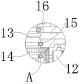
FIG. 4 is an enlarged view of the structure at A in FIG. 1 according to the present invention;
FIG. 5 is an enlarged view of the structure at B in FIG. 1 according to the present invention.
In the figure: 1. a substrate; 2. a water inlet pipe; 3. a drain pipe; 4. a reagent tube; 5. a sealing door; 6. a control panel; 7. a filter cup; 8. a threaded rod; 9. fixing the bolt; 10. filtering the mesh plate; 11. an adsorption material; 12. a servo motor; 13. a rotating shaft; 14. a bevel gear set; 15. a limiting bearing; 16. a main gear; 17. gear division; 18. a stirring rod.
Detailed Description
The technical solutions in the embodiments of the present invention will be clearly and completely described below with reference to the drawings in the embodiments of the present invention, and it is obvious that the described embodiments are only a part of the embodiments of the present invention, and not all of the embodiments.
Referring to fig. 1-5, the present invention provides a technical solution: a furniture production waste liquid recycling device; the shape of the base body 1 is a cuboid structure, a cavity is arranged in the base body 1, and the base body 1 is provided with a water inlet and drainage mechanism; the water inlet and drainage mechanism of the base body 1 comprises: the water inlet pipe 2 is arranged at the upper end of the base body 1, the water outlet pipe 3 is further arranged below the left end of the base body 1, and the reagent pipe 4 is arranged above the left side of the base body 1, so that the device is provided with a feeding and discharging mechanism, when the water inlet pipe 2 is opened, waste liquid to be treated can be placed into the device, the water outlet pipe 3 is used for discharging the treated waste liquid, and the reagent pipe 4 is used for adding a proper amount of chemical reagent to purify the waste liquid;
the method comprises the following steps:
the sealed door 5 is arranged on the outer side of the substrate 1, the sealed door 5 and the substrate 1 form a rotating mechanism, and the sealed door 5 is provided with a control mechanism; the control mechanism of the airtight door 5 comprises: the control panel 6 is arranged on the front side of the sealed door 5, so that the device is convenient to operate, the sealing gasket is arranged on the inner side of the sealed door 5, so that the compartment inside the matrix 1 can be isolated, the waste liquid cannot undergo grade-skipping purification treatment, and the control panel 6 is convenient for a user to control the device;
the shape of the filter cup 7 is a cylindrical mechanism, a through hole is formed in the surface of the filter cup 7, and the filter cup 7 is provided with a filtering and adsorbing mechanism; the filtering and adsorbing mechanism of the filter cup 7 comprises: threaded rod 8 sets up in the upper end of filtering cup 7, and threaded rod 8 is provided with 4 altogether, and threaded rod 8's surface is connecting fixing bolt 9, and the filtration adsorption apparatus who filters cup 7 still includes: the filter mesh plate 10 is arranged inside the matrix 1, 2 filter mesh plates 10 are arranged, and the adsorption material 11 is arranged between the filter mesh plates 10, so that the device is convenient to disassemble and maintain, the fixing bolt 9 on the outer side of the threaded rod 8 at the upper end of the filter cup 7 is unscrewed by a wrench, the filter cup 7 can be separated from the inside of the matrix 1, when waste liquid flows into the matrix 1 along the water inlet pipe 2, the waste liquid firstly enters the filter cup 7, the through holes on the surface of the filter cup 7 filter and screen larger impurity particles in the waste liquid, the first-stage filtration is completed, the waste liquid flows into the filter mesh plate 10, the filter mesh plate 10 carries out secondary filtration and screening on the particle impurities in the waste liquid, then the waste liquid upwards gushes to contact the adsorption material 11, and the adsorption material 11 absorbs pigment precipitates in the waste liquid;
the servo motor 12 is arranged at the inner bottom end of the base body 1, the servo motor 12 is waterproof, and the servo motor 12 is provided with a stirring mechanism; the stirring mechanism of the servo motor 12 includes: the rotating shaft 13 is arranged in the base body 1, the outer side of the rotating shaft 13 is provided with a bevel gear set 14, and the outer side of the rotating shaft 13 is also provided with a limiting bearing 15; the main gear 16 is arranged at the top end of the rotating shaft 13, the main gear 16 and the sub-gear 17 form a gear meshing mechanism, and the upper end of the sub-gear 17 is connected with the stirring rod 18, so that the device is provided with a stirring mechanism, the control panel 6 outside the airtight door 5 is operated to start the servo motor 12 inside the basal body 1, the servo motor 12 drives the bevel gear set 14 to rotate, the bevel gear set 14 drives the rotating shaft 13 to rotate, the rotating shaft 13 drives the main gear 16 at the upper end of the rotating shaft to rotate, the main gear 16 drives the sub-gear 17 to rotate, the sub-gear 17 drives the stirring rod 18 to rotate, and the stirring rod 18 stirs the waste liquid;
the working principle is as follows: when the furniture production waste liquid recycling equipment is used, firstly, the water inlet pipe 2 on the right side of the upper end of the base body 1 is opened, at the moment, waste liquid flows into the base body 1 along the water inlet pipe 2, the waste liquid firstly enters the filter cup 7, the through holes on the surface of the filter cup 7 filter and screen large impurity particles in the waste liquid to complete first-stage filtration, then the waste liquid flows into the filter mesh plate 10, the filter mesh plate 10 performs secondary filtration and screening on the particle impurities in the waste liquid, then the waste liquid upwards swells and contacts the adsorption material 11, the adsorption material 11 absorbs pigment precipitates in the waste liquid, finally the waste liquid enters the compartment where the stirring rod 18 is located, at the moment, the control panel 6 on the outer side of the operation sealed door 5 starts the servo motor 12 in the base body 1, the servo motor 12 drives the bevel gear set 14 to rotate, the bevel gear set 14 drives the rotating shaft 13 to rotate, and the rotating shaft 13 drives the main gear 16 on the upper end to rotate, the main gear 16 drives the branch gear 17 to rotate, the branch gear 17 drives the stirring rod 18 to rotate, the stirring rod 18 stirs the waste liquid, then the reagent pipe 4 on the left side of the basal body 1 is opened, a proper amount of chemical reagent is added to purify the waste liquid, so that the classified filtration is realized, the waste liquid is ensured to be completely treated to the maximum extent, and the finally treated waste liquid flows out along the drain pipe 3 for repeated use.
To thereby carry out a series of tasks, the contents of which are not described in detail in the present specification are prior art well known to those skilled in the art.
It will be evident to those skilled in the art that the utility model is not limited to the details of the foregoing illustrative embodiments, and that the present invention may be embodied in other specific forms without departing from the spirit or essential attributes thereof. The present embodiments are therefore to be considered in all respects as illustrative and not restrictive, the scope of the utility model being indicated by the appended claims rather than by the foregoing description, and all changes which come within the meaning and range of equivalency of the claims are therefore intended to be embraced therein. Any reference sign in a claim should not be construed as limiting the claim concerned.
Claims (6)
1. A furniture production waste liquid recycling device;
the water inlet and drainage structure comprises a base body (1), wherein the appearance of the base body is of a cuboid structure, a cavity is formed in the base body (1), and a water inlet and drainage mechanism is arranged on the base body (1);
it is characterized by comprising the following steps:
the closed door (5) is arranged on the outer side of the base body (1), the closed door (5) and the base body (1) form a rotating mechanism, and the closed door (5) is provided with a control mechanism;
the filtering cup (7) is a cylindrical mechanism, a through hole is formed in the surface of the filtering cup (7), and the filtering cup (7) is provided with a filtering and adsorbing mechanism;
servo motor (12), it sets up the inside bottom of base member (1), servo motor (12) are waterproof, and servo motor (12) are provided with rabbling mechanism.
2. The furniture production waste liquid recycling device according to claim 1, characterized in that: the water inlet and drainage mechanism of the base body (1) comprises:
the water inlet pipe (2) is arranged at the upper end of the base body (1), a water outlet pipe (3) is further arranged below the left end of the base body (1), and a reagent pipe (4) is arranged above the left side of the base body (1).
3. The furniture production waste liquid recycling device according to claim 1, characterized in that: the control mechanism of the airtight door (5) comprises:
and the control panel (6) is arranged on the front surface of the closed door (5).
4. The furniture production waste liquid recycling device according to claim 1, characterized in that: the filtration and adsorption mechanism of the filter cup (7) comprises:
the threaded rods (8) are arranged at the upper ends of the filter cups (7), the number of the threaded rods (8) is totally 4, and the surfaces of the threaded rods (8) are connected with fixing bolts (9).
5. The furniture production waste liquid recycling device according to claim 1, characterized in that: the stirring mechanism of the servo motor (12) comprises:
the rotating shaft (13) is arranged inside the base body (1), a bevel gear set (14) is arranged on the outer side of the rotating shaft (13), and a limiting bearing (15) is further arranged on the outer side of the rotating shaft (13);
the main gear (16) is arranged at the top end of the rotating shaft (13), the main gear (16) and the branch gear (17) form a gear meshing mechanism, and the upper end of the branch gear (17) is connected with the stirring rod (18).
6. The furniture production waste liquid recycling device according to claim 4, characterized in that: the filtration and adsorption mechanism of the filter cup (7) further comprises:
the filter screen plate (10) is arranged inside the base body (1), the number of the filter screen plates (10) is 2, and adsorption materials (11) are arranged between the filter screen plates (10).
Priority Applications (1)
| Application Number | Priority Date | Filing Date | Title |
|---|---|---|---|
| CN202220489521.8U CN216997973U (en) | 2022-03-09 | 2022-03-09 | Furniture production waste liquid cyclic utilization equipment |
Applications Claiming Priority (1)
| Application Number | Priority Date | Filing Date | Title |
|---|---|---|---|
| CN202220489521.8U CN216997973U (en) | 2022-03-09 | 2022-03-09 | Furniture production waste liquid cyclic utilization equipment |
Publications (1)
| Publication Number | Publication Date |
|---|---|
| CN216997973U true CN216997973U (en) | 2022-07-19 |
Family
ID=82369331
Family Applications (1)
| Application Number | Title | Priority Date | Filing Date |
|---|---|---|---|
| CN202220489521.8U Active CN216997973U (en) | 2022-03-09 | 2022-03-09 | Furniture production waste liquid cyclic utilization equipment |
Country Status (1)
| Country | Link |
|---|---|
| CN (1) | CN216997973U (en) |
-
2022
- 2022-03-09 CN CN202220489521.8U patent/CN216997973U/en active Active
Similar Documents
| Publication | Publication Date | Title |
|---|---|---|
| CN112387031B (en) | A exhaust gas filtering device for chemical production | |
| CN106045205A (en) | Industrial wastewater treatment device | |
| CN213231741U (en) | Industrial wastewater filtering device | |
| CN216997973U (en) | Furniture production waste liquid cyclic utilization equipment | |
| CN112850953A (en) | Waste water solid-liquid separation device | |
| CN216236386U (en) | High-efficient centrifugal sewage treatment plant | |
| CN214571121U (en) | Effluent treatment plant is used in pesticide production | |
| CN207418475U (en) | A kind of organic waste water treating device | |
| CN211935795U (en) | Environment-friendly filter equipment for sewage treatment | |
| CN213285901U (en) | Filtration equipment for industrial wastewater treatment | |
| CN112028374B (en) | Copper industry sewage treatment plant with metal recovery function | |
| CN115463745A (en) | Automatic extraction and enrichment device for micro-nano plastics in soil/sediment and using method thereof | |
| CN212246594U (en) | Sewage treatment equipment based on sewage centralized treatment technology | |
| CN213357141U (en) | Green sewage grading cleaning equipment | |
| CN209619154U (en) | A kind of sewage treatment sludge filtration device | |
| CN206799332U (en) | A kind of industrial wastewater heavy metal ion oxidation-adsorption circulation and stress environmental protection reaction unit | |
| CN111661961A (en) | Sewage treatment equipment based on sewage centralized treatment technology | |
| CN219440816U (en) | Domestic sewage quick purification device | |
| CN212581625U (en) | Oil-water separator with multiple filtering mechanism | |
| CN215311325U (en) | But discharge apparatus that peculiar smell was eliminated for industrial waste treatment | |
| CN213965359U (en) | Water pollution administers and uses filter equipment | |
| CN219991381U (en) | Environment-friendly treatment equipment for lead-containing wastewater | |
| CN213623560U (en) | Laboratory effluent treatment plant | |
| CN220788218U (en) | Water treatment separation equipment | |
| CN220642671U (en) | Fertilizer waste water recovery filter equipment |
Legal Events
| Date | Code | Title | Description |
|---|---|---|---|
| GR01 | Patent grant | ||
| GR01 | Patent grant |