CN216980309U - Ignition coil for natural gas generator set - Google Patents
Ignition coil for natural gas generator set Download PDFInfo
- Publication number
- CN216980309U CN216980309U CN202122905885.8U CN202122905885U CN216980309U CN 216980309 U CN216980309 U CN 216980309U CN 202122905885 U CN202122905885 U CN 202122905885U CN 216980309 U CN216980309 U CN 216980309U
- Authority
- CN
- China
- Prior art keywords
- fixedly connected
- shell
- sides
- ignition coil
- shaped movable
- Prior art date
- Legal status (The legal status is an assumption and is not a legal conclusion. Google has not performed a legal analysis and makes no representation as to the accuracy of the status listed.)
- Active
Links
Images


Landscapes
- Ignition Installations For Internal Combustion Engines (AREA)
Abstract
The utility model belongs to the field of ignition coils, and particularly relates to an ignition coil for a natural gas generator set, which comprises an inner shell; a metal shell is sleeved on the outer side of the inner shell; the top parts of the inner shell and the metal shell are provided with end covers together; the end cover and the top ends of the two sides of the metal shell are both provided with through holes together; the top ends of the two sides of the inner shell are provided with transverse grooves; one sides of the two transverse grooves close to each other are provided with a circular cavity together; the through hole and the transverse groove are both connected with a T-shaped movable rod in a sliding manner; the other end of each T-shaped movable rod is fixedly connected with a cross rod, and the cross rods are located in the circular cavities; the outer sides of the T-shaped movable rods are sleeved with first springs; one end of the first spring is fixedly connected with the end cover, and the other end of the first spring is fixedly connected with the T-shaped movable rod; the structure is convenient for installing the external shell of the ignition coil, does not need injection molding, is favorable for reducing the cost and quickens the assembly efficiency.
Description
Technical Field
The utility model relates to the field of ignition coils, in particular to an ignition coil for a natural gas generator set.
Background
The ignition coil is an ignition device for a generator set.
The core components of the ignition device are an ignition coil and a switching device, the energy of the ignition coil is increased, and a spark plug can generate sparks with enough energy.
In the prior art, when the external shell of the ignition coil is assembled, injection molding is needed, so that special molding equipment is needed, but the injection molding mode has high cost and low efficiency; therefore, an ignition coil for a natural gas generator set is provided to solve the above problems.
SUMMERY OF THE UTILITY MODEL
In order to make up for the defects of the prior art and solve the problems that when the outer shell of the ignition coil is assembled, the injection molding is needed, and therefore special molding equipment is needed, but the mode of assembling the outer shell through the injection molding is high in cost and low in efficiency, the utility model provides the ignition coil for the natural gas generator set.
The technical scheme adopted by the utility model for solving the technical problems is as follows: the utility model relates to an ignition coil for a natural gas generator set, which comprises an inner shell; a metal shell is sleeved on the outer side of the inner shell; the top parts of the inner shell and the metal shell are jointly provided with an end cover; the end cover and the top ends of the two sides of the metal shell are both provided with through holes together; the top ends of the two sides of the inner shell are both provided with transverse grooves; one sides of the two transverse grooves close to each other are provided with a round cavity together; the through hole and the transverse groove are both connected with a T-shaped movable rod in a sliding manner; the other end of each T-shaped movable rod is fixedly connected with a cross rod, and the cross rods are located in the circular cavities; the outer sides of the T-shaped movable rods are sleeved with first springs; one end of the first spring is fixedly connected with the end cover, and the other end of the first spring is fixedly connected with the T-shaped movable rod; the structure is convenient for installing the external shell of the ignition coil, does not need injection molding, is favorable for reducing the cost and quickens the assembly efficiency.
Preferably, a supporting shell is arranged inside the inner shell; an iron core is arranged inside the supporting shell; a primary coil is wound on the outer side of the iron core; the outer ring surface of the supporting shell is provided with a winding groove; the supporting shell is wound with a secondary coil through a winding slot; the bottom end of the supporting shell is fixedly connected with a connecting rod; an inserting groove is formed in the bottom end of the inner shell; the bottom end of the inserting groove is provided with an inner cavity; a group of second springs is fixedly connected to the bottom end of the inner cavity; the top ends of the second springs are fixedly connected with an extrusion plate; the bottom end of the connecting rod is fixedly connected with a clamping rod, and the clamping rod is positioned in the inner cavity; this structure is convenient for install and dismantle the coil assembly, provides convenience when installing this ignition coil for the staff.
Preferably, sliding grooves are formed in the two sides of the inner part of the inner shell; the top end and the bottom end of the two sides of the supporting shell are fixedly connected with sliding rods, and the other ends of the sliding rods are located in the sliding grooves and are in sliding fit with the sliding grooves; the position of the supporting shell is limited, and the rotating condition of the supporting shell is avoided.
Preferably, a group of guide rods is fixedly connected to the bottom end of the extrusion plate; the bottom end of the inner cavity is provided with a group of guide grooves, and the bottom ends of the guide rods are positioned in the guide grooves and are in sliding fit with the guide grooves; the limiting effect is realized.
Preferably, both sides of the guide groove are provided with limiting sliding grooves; the bottom ends of the two sides of the guide rod are fixedly connected with limiting slide rods, and the other ends of the limiting slide rods are positioned in the limiting slide grooves and are in sliding fit with the limiting slide grooves; can carry on spacingly to the removal orbit of guide bar, avoid appearing the condition emergence that the guide bar breaks away from in the guide way completely.
Preferably, the bottom end of the end cover is fixedly connected with a concave elastic pad in a groove, and the top end of the iron core is attached to the bottom end of the concave elastic pad; the position of the iron core is further limited, and collision between the iron core and the end cover can be avoided.
The utility model has the advantages that:
1. according to the utility model, the two T-shaped movable rods are pulled to one side far away from the metal shell, then the two T-shaped movable rods are rotated, the force for pulling the T-shaped movable rods is released, the T-shaped movable rods can drive the cross rod to enter the circular cavity through the through hole and the transverse groove, the cross rod rotates, and the cross rod can be fixed through the transverse groove, so that the structure is convenient for installing the outer shell of the ignition coil, injection molding is not required, the cost is reduced, and the assembly efficiency is accelerated.
2. According to the utility model, the iron core is downwards extruded, then the iron core is rotated, the iron core drives the connecting rod to rotate, the connecting rod drives the clamping rod to rotate, when the clamping rod rotates to the position no longer corresponding to the inserting groove, the force for extruding the iron core is released, and at the moment, the extruding plate can extrude and fix the clamping rod under the tension action of the second spring, so that the position of the iron core is fixed, and further, the structure is convenient for installing and disassembling the coil device, and convenience is provided for workers to install the ignition coil.
Drawings
In order to more clearly illustrate the embodiments of the present invention or the technical solutions in the prior art, the drawings used in the description of the embodiments or the prior art will be briefly described below, and it is obvious that the drawings in the following description are only some embodiments of the present invention, and for those skilled in the art, other drawings can be obtained according to these drawings without inventive exercise.
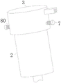
FIG. 1 is a perspective view of an ignition coil in accordance with one embodiment;
FIG. 2 is a schematic cross-sectional view of an ignition coil according to an embodiment;
FIG. 3 is an enlarged view of a portion of FIG. 2;
FIG. 4 is an enlarged view of a portion of FIG. 3 at B;
FIG. 5 is an enlarged view of a portion of FIG. 2 at C;
FIG. 6 is a schematic sectional view of an ignition coil according to a second embodiment;
fig. 7 is a partially enlarged view of a portion D in fig. 6.
In the figure: 1. an inner shell; 2. a metal shell; 3. an end cap; 4. a through hole; 5. a transverse slot; 6. a circular cavity; 7. a T-shaped movable rod; 8. a cross bar; 80. a first spring; 9. a support housing; 10. an iron core; 11. a primary coil; 12. a winding groove; 13. a secondary coil; 14. a connecting rod; 15. inserting into a groove; 16. an inner cavity; 17. a second spring; 18. a pressing plate; 100. a clamping rod; 19. a chute; 20. a slide bar; 21. a guide bar; 22. a guide groove; 23. a limiting slide bar; 24. a limiting chute; 25. a concave elastic pad; 26. a guide groove; 27. an L-shaped rod; 28. an annular groove; 29. and a guide block.
Detailed Description
The technical solutions in the embodiments of the present invention will be clearly and completely described below with reference to the drawings in the embodiments of the present invention, and it is obvious that the described embodiments are only a part of the embodiments of the present invention, and not all of the embodiments. All other embodiments, which can be derived by a person skilled in the art from the embodiments given herein without making any creative effort, shall fall within the protection scope of the present invention.
Example one
Referring to fig. 1-5, an ignition coil for a natural gas generator set includes an inner casing 1; a metal shell 2 is sleeved on the outer side of the inner shell 1; the top parts of the inner shell 1 and the metal shell 2 are provided with an end cover 3 together; the end cover 3 and the top ends of the two sides of the metal shell 2 are both provided with through holes 4; the top ends of the two sides of the inner shell 1 are both provided with transverse grooves 5; one sides of the two transverse grooves 5 close to each other are provided with a round cavity 6 together; the through hole 4 and the transverse groove 5 are both connected with a T-shaped movable rod 7 in a sliding manner; the other end of each T-shaped movable rod 7 is fixedly connected with a cross rod 8, and the cross rods 8 are located in the circular cavities 6; the outer sides of the T-shaped movable rods 7 are sleeved with first springs 80; one end of the first spring 80 is fixedly connected with the end cover 3, and the other end of the first spring 80 is fixedly connected with the T-shaped movable rod 7; during operation, the metal shell 2 is sleeved on the outer side of the inner shell 1, then the two T-shaped movable rods 7 are pulled to one side far away from the metal shell 2, at the moment, the T-shaped movable rods 7 drive the cross rod 8 to move to one side far away from the metal shell 2, then the two T-shaped movable rods 7 are rotated, so that the T-shaped movable rods 7 drive the cross rod 8 to rotate, as the T-shaped movable rods 7 are rotated, the first spring 80 is deformed, at the moment, the end cover 3 is covered on the top of the inner shell 1 and the metal shell 2, at the moment, the positions of the cross rod 8 and the through hole 4 are corresponding, then the force for pulling the T-shaped movable rods 7 is released, but the state of the cross rod 8 is kept, under the action of the first spring 80, the T-shaped movable rods 7 can drive the cross rod 8 to enter the circular cavity 6 through the through hole 4 and the transverse groove 5, at the moment, the original shape of the first spring 80 can be restored, the cross rod 8 rotates, and the cross rod 8 is in a vertical state, thereby can fix horizontal pole 8 through transverse groove 5, and then this structure is convenient for install the outside casing of ignition coil, need not injection moulding, is favorable to reduce cost for the efficiency of equipment.
A supporting shell 9 is arranged inside the inner shell 1; an iron core 10 is arranged inside the supporting shell 9; a primary coil 11 is wound on the outer side of the iron core 10; the outer ring surface of the supporting shell 9 is provided with a winding groove 12; the supporting case 9 is wound with a secondary coil 13 through a winding slot 12; the bottom end of the supporting shell 9 is fixedly connected with a connecting rod 14; an inserting groove 15 is formed in the bottom end of the inner part of the inner shell 1; an inner cavity 16 is formed at the bottom end of the inserting groove 15; a group of second springs 17 are fixedly connected to the bottom end of the inner cavity 16; the top ends of the second springs 17 are fixedly connected with a squeezing plate 18; the bottom end of the connecting rod 14 is fixedly connected with a clamping rod 100, and the clamping rod 100 is positioned in the inner cavity 16; in operation, the iron core 10 is placed inside the supporting shell 9, and the engaging rod 100 is aligned with the insertion slot 15, then the iron core 10 is pressed downwards, the iron core 10 drives the connecting rod 14 to move downwards, the connecting rod 14 drives the clamping rod 100 to move downwards, the clamping rod 100 enters the inserting groove 15 and then enters the inner cavity 16, and the clamping rod 100 will extrude the extruding plate 18, the second spring 17 is compressed, and then the iron core 10 is rotated, the iron core 10 drives the connecting rod 14 to rotate, the connecting rod 14 drives the clamping rod 100 to rotate, when the clamping rod 100 rotates to be no longer corresponding to the inserting groove 15, the force for extruding the iron core 10 is released, at this time, under the tension of the second spring 17, the extruding plate 18 extrudes and fixes the clamping rod 100, so that the position of the iron core 10 is fixed, and then this structure is convenient for install and dismantle the coil assembly, provides convenience when installing this ignition coil for the staff.
The two sides of the inner part of the inner shell 1 are both provided with sliding grooves 19; the top end and the bottom end of the two sides of the supporting shell 9 are fixedly connected with sliding rods 20, and the other ends of the sliding rods 20 are positioned in the sliding grooves 19 and are in sliding fit with the sliding grooves; during operation, the position of the supporting shell 9 can be limited by the arrangement of the sliding groove 19 and the sliding rod 20, so that the supporting shell 9 is prevented from rotating.
A group of guide rods 21 are fixedly connected to the bottom end of the extrusion plate 18; a group of guide grooves 22 are formed in the bottom end of the inner cavity 16, and the bottom ends of the guide rods 21 are located in the guide grooves 22 and are in sliding fit with the guide grooves 22; when the extrusion device works, the position of the extrusion plate 18 can be limited by the arrangement of the guide rod 21 and the guide groove 22, the extrusion plate 18 is prevented from rotating along with the rotation of the clamping rod 100, and therefore the limiting effect is achieved.
Both sides of the guide groove 22 are provided with limiting sliding grooves 24; the bottom ends of the two sides of the guide rod 21 are fixedly connected with limit slide rods 23, and the other ends of the limit slide rods 23 are positioned in the limit slide grooves 24 and are in sliding fit with the limit slide grooves; during operation, the limiting sliding groove 24 and the limiting sliding rod 23 are arranged, so that the moving track of the guide rod 21 can be limited, and the guide rod 21 is prevented from being completely separated from the guide groove 22.
A concave elastic pad 25 is fixedly connected to the bottom end of the end cover 3 in a groove manner, and the top end of the iron core 10 is attached to the bottom end of the concave elastic pad 25; in operation, by providing the concave elastic pad 25, the position of the iron core 10 can be further limited, and collision between the iron core 10 and the end cover 3 can be avoided.
Example two
Referring to fig. 6 to 7, in a first comparative example, as another embodiment of the present invention, guide grooves 26 are formed in front and rear sides of the inside of the supporting shell 9; an annular groove 28 is formed in the bottom of the inner annular surface of the supporting shell 9; the two ends of the supporting shell 9 are fixedly connected with L-shaped rods 27; the bottom ends of the L-shaped rods 27 are fixedly connected with guide blocks 29, and the guide blocks 29 are positioned in the annular grooves 28; during operation, the iron core 10 is installed, the two guide blocks 29 are aligned to the guide grooves 26 and slide downwards, the clamping rod 100 can be ensured to be aligned to the insertion groove 15 at the moment, then the iron core 10 is rotated, the guide blocks 29 slide into the annular groove 28, and then the iron core 10 can be positioned in the installation process by the aid of the structure.
Working principle, in operation, the iron core 10 is placed inside the supporting shell 9, and the engaging rod 100 is aligned with the inserting slot 15, then the iron core 10 is pressed downwards, the iron core 10 drives the connecting rod 14 to move downwards, the connecting rod 14 drives the clamping rod 100 to move downwards, the clamping rod 100 enters the inserting groove 15 and then enters the inner cavity 16, and the clamping rod 100 will extrude the extruding plate 18, the second spring 17 is compressed, and then the iron core 10 is rotated, the iron core 10 drives the connecting rod 14 to rotate, the connecting rod 14 drives the clamping rod 100 to rotate, when the clamping rod 100 rotates to be no longer corresponding to the inserting groove 15, the force for extruding the iron core 10 is released, at this time, under the tension of the second spring 17, the extruding plate 18 extrudes and fixes the clamping rod 100, so that the position of the iron core 10 is fixed, the structure is convenient for mounting and dismounting the coil device, and provides convenience for workers to mount the ignition coil;
then the metal shell 2 is sleeved outside the inner shell 1, then the two T-shaped movable rods 7 are pulled to one side far away from the metal shell 2, at the moment, the T-shaped movable rods 7 drive the cross rod 8 to move to one side far away from the metal shell 2, then the two T-shaped movable rods 7 are rotated, so that the T-shaped movable rods 7 drive the cross rod 8 to rotate, along with the rotation of the T-shaped movable rods 7, the first spring 80 deforms, at the moment, the end cover 3 covers the top of the inner shell 1 and the metal shell 2, at the moment, the positions of the cross rod 8 and the through hole 4 correspond, then the force for pulling the T-shaped movable rods 7 is released, but the state of the cross rod 8 is kept, under the action of the first spring 80, the T-shaped movable rods 7 can drive the cross rod 8 to enter the circular cavity 6 through the through hole 4 and the transverse groove 5, at the moment, the first spring 80 can recover, the original shape of the cross rod 8 rotates, the cross rod 8 is in a vertical state, and therefore, the cross rod 8 can be fixed through the transverse groove 5, and then this structure is convenient for install the outside casing of ignition coil, need not injection moulding, is favorable to reduce cost for the efficiency of equipment.
In the description herein, references to the description of "one embodiment," "an example," "a specific example," etc., mean that a particular feature, structure, material, or characteristic described in connection with the embodiment or example is included in at least one embodiment or example of the utility model. In this specification, the schematic representations of the terms used above do not necessarily refer to the same embodiment or example. Furthermore, the particular features, structures, materials, or characteristics described may be combined in any suitable manner in any one or more embodiments or examples.
The foregoing shows and describes the general principles, essential features, and advantages of the utility model. It will be understood by those skilled in the art that the present invention is not limited to the embodiments described above, which are described in the specification and illustrated only to illustrate the principle of the present invention, but that various changes and modifications may be made therein without departing from the spirit and scope of the present invention, which fall within the scope of the utility model as claimed.
Claims (6)
1. An ignition coil for a natural gas generator set, characterized in that: comprises an inner shell (1); a metal shell (2) is sleeved on the outer side of the inner shell (1); the top parts of the inner shell (1) and the metal shell (2) are provided with an end cover (3) together; the end cover (3) and the top ends of the two sides of the metal shell (2) are both provided with through holes (4); the top ends of the two sides of the inner shell (1) are provided with transverse grooves (5); one sides of the two transverse grooves (5) close to each other are provided with a circular cavity (6) together; the through hole (4) and the transverse groove (5) are connected with a T-shaped movable rod (7) in a sliding manner; the other ends of the T-shaped movable rods (7) are fixedly connected with cross rods (8), and the cross rods (8) are positioned in the circular cavity (6); the outer sides of the T-shaped movable rods (7) are sleeved with first springs (80); one end of the first spring (80) is fixedly connected with the end cover (3), and the other end of the first spring (80) is fixedly connected with the T-shaped movable rod (7).
2. The ignition coil for a natural gas electric generating set according to claim 1, characterized in that: a supporting shell (9) is arranged in the inner shell (1); an iron core (10) is arranged in the supporting shell (9); a primary coil (11) is wound on the outer side of the iron core (10); a winding groove (12) is formed in the outer annular surface of the supporting shell (9); the supporting shell (9) is wound with a secondary coil (13) through a winding groove (12); the bottom end of the supporting shell (9) is fixedly connected with a connecting rod (14); an inserting groove (15) is formed in the bottom end of the inner part of the inner shell (1); an inner cavity (16) is formed at the bottom end of the inserting groove (15); a group of second springs (17) are fixedly connected to the bottom end of the inner cavity (16); the top ends of the second springs (17) are fixedly connected with a squeezing plate (18); the bottom end of the connecting rod (14) is fixedly connected with a clamping rod (100), and the clamping rod (100) is located in the inner cavity (16).
3. The ignition coil for a natural gas electric generating set according to claim 2, characterized in that: the two sides of the inner part of the inner shell (1) are both provided with sliding chutes (19); the top and the bottom of supporting shell (9) both sides all are fixedly connected with slide bar (20), and the other end of slide bar (20) all is located spout (19) and with its sliding fit.
4. An ignition coil for a natural gas electric generating set according to claim 3, characterized in that: a group of guide rods (21) are fixedly connected to the bottom end of the extrusion plate (18); a set of guide way (22) has been seted up to the bottom of inner chamber (16), and the bottom of guide bar (21) all is located guide way (22) and rather than sliding fit.
5. The ignition coil for a natural gas electric generating set according to claim 4, characterized in that: both sides of the guide groove (22) are provided with limiting sliding grooves (24); the bottom of guide bar (21) both sides all the rigid coupling have spacing slide bar (23), and the other end of spacing slide bar (23) all is located spacing spout (24) and rather than sliding fit.
6. An ignition coil for a natural gas power plant according to claim 5, characterized in that: the bottom end of the end cover (3) is fixedly connected with a concave elastic pad (25) in a slotted mode, and the top end of the iron core (10) is attached to the bottom end of the concave elastic pad (25).
Priority Applications (1)
| Application Number | Priority Date | Filing Date | Title |
|---|---|---|---|
| CN202122905885.8U CN216980309U (en) | 2021-11-24 | 2021-11-24 | Ignition coil for natural gas generator set |
Applications Claiming Priority (1)
| Application Number | Priority Date | Filing Date | Title |
|---|---|---|---|
| CN202122905885.8U CN216980309U (en) | 2021-11-24 | 2021-11-24 | Ignition coil for natural gas generator set |
Publications (1)
| Publication Number | Publication Date |
|---|---|
| CN216980309U true CN216980309U (en) | 2022-07-15 |
Family
ID=82345123
Family Applications (1)
| Application Number | Title | Priority Date | Filing Date |
|---|---|---|---|
| CN202122905885.8U Active CN216980309U (en) | 2021-11-24 | 2021-11-24 | Ignition coil for natural gas generator set |
Country Status (1)
| Country | Link |
|---|---|
| CN (1) | CN216980309U (en) |
-
2021
- 2021-11-24 CN CN202122905885.8U patent/CN216980309U/en active Active
Similar Documents
| Publication | Publication Date | Title |
|---|---|---|
| CN216980309U (en) | Ignition coil for natural gas generator set | |
| CN210578101U (en) | Generator convenient to maintain | |
| CN202423192U (en) | Fuse chamber structure | |
| CN206908389U (en) | A kind of mounting structure of stator | |
| CN107872037B (en) | A kind of wall bushing component elastic support unit | |
| CN217152229U (en) | Control and display terminal of air compressor | |
| CN219535746U (en) | Digit control machine tool motor cabinet | |
| CN219257252U (en) | Novel high-voltage electric box | |
| CN209743376U (en) | high tension switchgear pressure release lid hinge | |
| CN117374636B (en) | High-voltage wire harness assembly for new energy automobile | |
| CN221042410U (en) | Wear-resistant stator coil holder | |
| CN221042596U (en) | Expansion die for ultra-thin long stator | |
| CN216311473U (en) | Assembled electric porcelain insulator | |
| CN218791712U (en) | Wall hanging rack for indoor network exchanger | |
| CN214897842U (en) | Novel insulating column with shock-absorbing structure | |
| CN219180694U (en) | Quick and reliable spring mounting structure | |
| CN211930367U (en) | Motor stator coil with small abrasion degree | |
| CN218769296U (en) | Auxiliary contact module of contactor type relay | |
| CN212967512U (en) | Indoor high-voltage grounding switch | |
| CN218472924U (en) | Protective noise reduction motor housing | |
| CN219936810U (en) | Explosion-proof reactor | |
| CN218071141U (en) | Energy-saving direct current motor with insulation framework structure | |
| CN216287863U (en) | Epoxy resin pouring type smoothing reactor | |
| CN220254841U (en) | General power supply box locking structure of LED display screen | |
| CN218768984U (en) | Transformer framework installation fixed knot constructs |
Legal Events
| Date | Code | Title | Description |
|---|---|---|---|
| GR01 | Patent grant | ||
| GR01 | Patent grant |