CN216966962U - Full-automatic table frame is with curved frame equipment - Google Patents
Full-automatic table frame is with curved frame equipment Download PDFInfo
- Publication number
- CN216966962U CN216966962U CN202220769232.3U CN202220769232U CN216966962U CN 216966962 U CN216966962 U CN 216966962U CN 202220769232 U CN202220769232 U CN 202220769232U CN 216966962 U CN216966962 U CN 216966962U
- Authority
- CN
- China
- Prior art keywords
- frame
- bending
- mounting plate
- fixedly connected
- cutting knife
- Prior art date
- Legal status (The legal status is an assumption and is not a legal conclusion. Google has not performed a legal analysis and makes no representation as to the accuracy of the status listed.)
- Active
Links
Images


Abstract
The utility model provides frame bending equipment for a full-automatic table frame, and relates to the technical field of tables; the device comprises a transmission assembly arranged at the upper end of the surface of a rack, wherein a fixed plate is fixedly connected to one end side of the rack, a mounting plate is arranged at the upper end of the surface of the fixed plate, a bending die matched with the transmission assembly is fixedly connected to one end, close to the rack, of the surface of the mounting plate, an electric telescopic rod is arranged at the other end of the mounting plate, a cutting knife is fixedly connected to a telescopic shaft of the electric telescopic rod, one end, close to the rack, of the mounting plate is rotatably connected with the fixed plate, an arc-shaped adjusting groove penetrates through the surface of the fixed plate, an adjusting shaft penetrating through the fixed plate through the arc-shaped adjusting groove is fixedly connected to the rear side of the other end of the mounting plate, and a fixing nut which is sleeved on the surface of the adjusting shaft in a threaded manner is arranged on the rear side of the fixed plate; the utility model is convenient for adjusting the positions of the bending die and the transmission assembly according to the bending angle of the table frame, has simple operation and simultaneously improves the practicability of the device and the production cost of the table frame.
Description
Technical Field
The utility model relates to the field of tables, in particular to a frame bending device for a full-automatic table frame.
Background
In order to meet the requirements of the public, the types of the table are rich and various, the table generally comprises a table top, a table frame and table legs, and meanwhile, the table can be divided into a plurality of categories according to the requirements, such as an office table, a dining table, a desk, a computer table, a teacher's table, a mahjong table and the like, and the table has a rectangular shape, a square shape, a circular shape, a fan shape and the like.
In the prior art, the table frame is provided with the straight frame and the bent frame, when the bent frame is produced, bending equipment is required to be used, but the existing bending equipment can only be used for processing the bent frame with one size generally, when the bent frames with different sizes are processed, the bending equipment matched with the bending equipment is required to be used for processing, the practicability is low, the production cost of the table frame is increased, and therefore the full-automatic table frame bending equipment is provided.
Disclosure of Invention
In order to overcome the defects of the prior art, the utility model provides a frame bending device for a full-automatic table frame, which aims to solve the problems in the background art.
In order to solve the technical problems, the utility model provides the following technical scheme: the utility model provides a full-automatic table frame is with curved frame equipment, is including setting up the drive assembly in rack surface upper end, frame one end side rigid coupling has the fixed plate, the upper end on fixed plate surface is provided with the mounting panel, the one end rigid coupling that the mounting panel surface is close to the frame have with the mould of bending of drive assembly adaptation, the mounting panel other end is provided with electric telescopic handle, and electric telescopic handle telescopic shaft rigid coupling has the cutting knife, the one end that the mounting panel is close to the frame rotates with the fixed plate to be connected, the fixed plate surface runs through there is the arc adjustment tank, the rear side rigid coupling of the mounting panel other end has the regulating spindle that runs through the fixed plate through the arc adjustment tank, the fixed plate rear side is provided with the fixation nut that the screw thread bush was established on the regulating spindle surface.
As a preferable technical scheme of the utility model, the transmission assembly comprises transmission wheels in a linear array and driven wheels arranged at the upper ends of the transmission wheels, a connection shaft of each driven wheel is connected with the surface of the rack in a sliding manner, a driving motor is arranged on the surface of the lower end of the rack, and the driving end of each driving motor drives a plurality of transmission wheels to rotate simultaneously through the matching of a plurality of groups of belts and belt pulleys.
As a preferable technical scheme of the utility model, the electric telescopic rod is arranged on the surface of the mounting plate through a tightening hoop.
As a preferred technical scheme of the utility model, the telescopic shaft of the electric telescopic rod is fixedly connected with a tool apron, one end of the tool apron is provided with a clamping groove, and one end of the cutting knife is inserted into the clamping groove and fixedly connected through a bolt.
As a preferred technical scheme of the utility model, a bending through groove vertically penetrates through the middle part of the bending die, a cutting knife groove transversely penetrates through the end side of the bending die, and the cutting knife is matched with the cutting knife groove.
As a preferred technical scheme of the utility model, the bending die is connected with the surface of the mounting plate in a split mode through bolts.
Compared with the prior art, the utility model can achieve the following beneficial effects:
according to the utility model, through the use of the fixing nut, the adjusting shaft and the arc-shaped adjusting groove, the angle between the bending die and the transmission assembly is adjusted, so that the positions of the bending die and the transmission assembly are conveniently adjusted according to the bending angle of the table frame, the operation is simple, and meanwhile, the practicability of the device and the production cost of the table frame are improved.
Drawings
In order to more clearly illustrate the technical solutions of the embodiments of the present invention, the drawings that are required to be used in the embodiments will be briefly described below, it should be understood that the following drawings only illustrate some embodiments of the present invention and therefore should not be considered as limiting the scope, and for those skilled in the art, other related drawings can be obtained according to the drawings without inventive efforts.
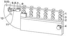
FIG. 1 is a schematic structural view of the present invention;
FIG. 2 is a partial rear view of the fixation plate of the present invention;
FIG. 3 is a schematic view of a connection structure of the electric telescopic rod and the cutting knife of the present invention.
Description of the main elements
1. A frame; 2. a driving wheel; 3. a driven wheel; 4. a drive motor; 5. a fixing plate; 6. mounting a plate; 7. bending the die; 8. bending the through groove; 9. cutting a cutter groove; 10. an electric telescopic rod; 11. a cutting knife; 12. an arc-shaped adjusting groove; 13. an adjustment shaft; 14. fixing a nut; 15. a tool apron; 16. a clamping groove.
Detailed Description
In order to make the objects, technical solutions and advantages of the embodiments of the present invention more apparent, the technical solutions of the embodiments of the present invention will be described clearly and completely with reference to the accompanying drawings of the embodiments of the present invention, and it is obvious that the described embodiments are some, but not all embodiments of the present invention. All other embodiments, which can be obtained by a person skilled in the art without any inventive step based on the embodiments of the present invention, are within the scope of the present invention. Thus, the following detailed description of the embodiments of the present invention, presented in the figures, is not intended to limit the scope of the utility model, as claimed, but is merely representative of selected embodiments of the utility model. All other embodiments, which can be obtained by a person skilled in the art without any inventive step based on the embodiments of the present invention, are within the scope of the present invention.
In the present invention, unless otherwise explicitly stated or limited, the terms "mounted," "connected," "fixed," and the like are to be construed broadly, e.g., as being permanently connected, detachably connected, or integral; can be mechanically or electrically connected; either directly or indirectly through intervening media, either internally or in any other relationship. The specific meanings of the above terms in the present invention can be understood by those skilled in the art according to specific situations.
In the present invention, unless otherwise expressly stated or limited, "above" or "below" a first feature means that the first and second features are in direct contact, or that the first and second features are not in direct contact but are in contact with each other via another feature therebetween. Also, the first feature being "on," "above" and "over" the second feature includes the first feature being directly on and obliquely above the second feature, or merely indicating that the first feature is at a higher level than the second feature. "beneath," "under" and "beneath" a first feature includes the first feature being directly beneath and obliquely beneath the second feature, or simply indicating that the first feature is at a lesser elevation than the second feature.
Examples
As shown in figures 1 and 2, the utility model provides a frame bending device for a full-automatic table frame, which comprises a transmission assembly arranged at the upper end of the surface of a frame 1, wherein one end side of the frame 1 is fixedly connected with a fixed plate 5, the upper end of the surface of the fixed plate 5 is provided with a mounting plate 6, one end of the surface of the mounting plate 6, which is close to the frame 1, is fixedly connected with a bending die 7 matched with the transmission assembly, the other end of the mounting plate 6 is provided with an electric telescopic rod 10, the electric telescopic rod 10 is mounted on the surface of the mounting plate 6 through a tightening hoop, a cutting knife 11 is fixedly connected with an expansion shaft of the electric telescopic rod 10, a bending through groove 8 is vertically penetrated in the middle of the bending die 7, a cutting knife groove 9 is transversely penetrated at the end side of the bending die, the cutting knife 11 is matched with the cutting knife groove 9, one end of the mounting plate 6, which is close to the frame 1, is rotatably connected with the fixed plate 5, an arc-shaped adjusting groove 12 is penetrated through the surface of the fixed plate 5, an adjusting shaft 13 which is fixedly connected with the rear side of the other end of the mounting plate 6, a fixed nut 14 which is sleeved on the surface of the adjusting shaft 13 through threads is arranged on the rear side of the fixed plate 5;
in the embodiment, the raw material for bending the table frame is conveyed through the transmission assembly, the end part of the raw material is bent by a tool and inserted into the bending through groove 8 in the bending die 7, then the raw material is conveyed and automatically bent through the transmission assembly, meanwhile, when the raw material is bent to a certain length, the electric telescopic rod 10 drives the cutting knife 11 to be inserted into the cutting knife groove 9 to cut off the raw material, then the transmission assembly is used for transmission and bending, when the bending angle of the raw material is adjusted, the fixing nut 14 is firstly screwed to be separated from the fixing plate 5, then the adjusting shaft 13 slides along the arc-shaped adjusting groove 12 and drives the mounting plate 6 to rotate, the bending die 7 is driven to a proper angle, after the adjustment is completed, the fixing nut 14 drives the adjusting shaft 13 to clamp the surface of the fixing plate 5, and further the mounting plate 6 is fixed, the device is convenient for adjusting the positions of the bending die 7 and the transmission assembly according to the bending angle of the table frame, the operation is simple, and the practicability of the equipment and the production cost of the table frame are improved.
As shown in fig. 1, the embodiment discloses that the transmission assembly includes transmission wheels 2 in a linear array and driven wheels 3 disposed at the upper ends of the transmission wheels 2, a connecting shaft of the driven wheels 3 is slidably connected with the surface of the frame 1, a driving motor 4 is disposed on the surface of the lower end of the frame 1, and the driving end of the driving motor 4 drives a plurality of transmission wheels 2 to rotate simultaneously through the cooperation of a plurality of groups of belts and belt pulleys;
in this embodiment, drive wheel 2 simultaneously and rotate through the use of driving motor 4 cooperation multiunit belt and belt pulley, and drive from driving wheel 3 synchronous rotation through the effect of frictional force, and then realize the conveying of raw materials.
As shown in fig. 3, in the embodiment, a tool holder 15 is fixedly connected to a telescopic shaft of the electric telescopic rod 10, a clamping groove 16 is formed at one end of the tool holder 15, and one end of the cutting knife 11 is inserted into the clamping groove 16 and fixedly connected thereto through a bolt;
in this embodiment, when installing cutting knife 11, at first with cutting knife 11's installation section embedding draw-in groove 16 to install through the bolt, realize cutting knife 11 and electric telescopic handle 10's split type and be connected, be convenient for to cutting knife 11's dismantlement and installation, and then be convenient for to cutting knife 11's change, prevent that the passivation from appearing in the long-time use of cutting knife 11 and reduce the cutting effect.
As shown in fig. 1, the embodiment discloses that the bending die 7 is connected with the surface of the mounting plate 6 in a split manner through bolts;
in this embodiment, the bending die 7 is connected with the mounting plate 6 through a bolt, so that the bending die 7 can be conveniently disassembled, the bending die 7 can be conveniently replaced, abrasion caused by long-time use of the bending die 7 is prevented, and the bending effect of the table frame is reduced.
The above description is only a preferred embodiment of the present invention and is not intended to limit the present invention, and various modifications and changes may be made by those skilled in the art. Any modification, equivalent replacement, or improvement made within the spirit and principle of the present invention should be included in the protection scope of the present invention.
Claims (6)
1. The utility model provides a full-automatic table frame is with curved frame equipment, is including setting up the drive assembly in frame (1) surface upper end, its characterized in that: a fixed plate (5) is fixedly connected at one end side of the frame (1), a mounting plate (6) is arranged at the upper end of the surface of the fixed plate (5), one end of the surface of the mounting plate (6) close to the rack (1) is fixedly connected with a bending die (7) matched with the transmission assembly, the other end of the mounting plate (6) is provided with an electric telescopic rod (10), and the telescopic shaft of the electric telescopic rod (10) is fixedly connected with a cutting knife (11), one end of the mounting plate (6) close to the machine frame (1) is rotatably connected with the fixing plate (5), an arc-shaped adjusting groove (12) penetrates through the surface of the fixing plate (5), an adjusting shaft (13) penetrating through the fixing plate (5) through the arc-shaped adjusting groove (12) is fixedly connected with the rear side of the other end of the mounting plate (6), and a fixing nut (14) which is sleeved on the surface of the adjusting shaft (13) through threads is arranged on the rear side of the fixing plate (5).
2. The frame bending apparatus for a fully automatic table frame as claimed in claim 1, wherein: the transmission assembly comprises transmission wheels (2) in a linear array and driven wheels (3) arranged at the upper ends of the transmission wheels (2), a connecting shaft of each driven wheel (3) is connected with the surface of the rack (1) in a sliding mode, a driving motor (4) is arranged on the surface of the lower end of the rack (1), and the driving ends of the driving motors (4) drive the transmission wheels (2) to rotate simultaneously through the matching of a plurality of groups of belts and belt pulleys.
3. The frame bending device for the full-automatic table frame as claimed in claim 1, wherein: the electric telescopic rod (10) is installed on the surface of the installation plate (6) through a tightening hoop.
4. The frame bending apparatus for a fully automatic table frame as claimed in claim 1, wherein: the electric telescopic rod (10) is fixedly connected with a tool apron (15), one end of the tool apron (15) is provided with a clamping groove (16), and one end of the cutting knife (11) is inserted into the clamping groove (16) and fixedly connected through a bolt.
5. The frame bending apparatus for a fully automatic table frame as claimed in claim 1, wherein: the middle part of the bending die (7) is vertically penetrated with a bending through groove (8), the end side of the bending through groove is transversely penetrated with a cutting knife groove (9), and the cutting knife (11) is matched with the cutting knife groove (9).
6. The frame bending device for the full-automatic table frame as claimed in claim 1, wherein: the bending die (7) is connected with the surface of the mounting plate (6) in a split mode through bolts.
Priority Applications (1)
| Application Number | Priority Date | Filing Date | Title |
|---|---|---|---|
| CN202220769232.3U CN216966962U (en) | 2022-04-06 | 2022-04-06 | Full-automatic table frame is with curved frame equipment |
Applications Claiming Priority (1)
| Application Number | Priority Date | Filing Date | Title |
|---|---|---|---|
| CN202220769232.3U CN216966962U (en) | 2022-04-06 | 2022-04-06 | Full-automatic table frame is with curved frame equipment |
Publications (1)
| Publication Number | Publication Date |
|---|---|
| CN216966962U true CN216966962U (en) | 2022-07-15 |
Family
ID=82342226
Family Applications (1)
| Application Number | Title | Priority Date | Filing Date |
|---|---|---|---|
| CN202220769232.3U Active CN216966962U (en) | 2022-04-06 | 2022-04-06 | Full-automatic table frame is with curved frame equipment |
Country Status (1)
| Country | Link |
|---|---|
| CN (1) | CN216966962U (en) |
-
2022
- 2022-04-06 CN CN202220769232.3U patent/CN216966962U/en active Active
Similar Documents
| Publication | Publication Date | Title |
|---|---|---|
| WO2022017495A1 (en) | Rotary cutting machine using automatic stepless shifting of cam to change rotary cutting veneer thickness | |
| CN216966962U (en) | Full-automatic table frame is with curved frame equipment | |
| CN217256548U (en) | Foam splitting machine | |
| CN112475896B (en) | Steel plate cutting equipment | |
| CN109822681A (en) | A kind of adjustable cutting angle wood sawing machine | |
| CN109866260B (en) | Film cutting machine | |
| CN109066488B (en) | High-voltage cable peeling treatment device | |
| CN219987035U (en) | Vertical shaft circular knife edging machine convenient to clear up | |
| CN215788471U (en) | Efficient cutting device for processing bus duct | |
| CN218285919U (en) | Numerical control double-sided thicknesser device for display cabinet plates | |
| CN220969423U (en) | Grinding device for food pretreatment | |
| CN219188851U (en) | Angle-adjustable trimming machine | |
| CN213085813U (en) | Automatic linear cutting machine for glass plates | |
| CN220575184U (en) | Alternate screw driving die | |
| CN219276028U (en) | Film production machine | |
| CN218427421U (en) | Panel conveying assembly of wooden board trimmer | |
| CN210148471U (en) | A high-efficient slicer for mixing rubber | |
| CN112960900B (en) | Automatic cutting device of borosilicate fire-proof glass | |
| CN215431770U (en) | End-to-end cutting device for bar processing production | |
| CN211967695U (en) | Drawing cutting device | |
| CN220703526U (en) | Adjusting structure for glass cutting | |
| CN219274619U (en) | Photovoltaic board frame section bar processing equipment | |
| CN219767054U (en) | Cutting device is used in valve plate processing | |
| CN214055464U (en) | Belt circle cutting machine | |
| CN214559187U (en) | Milling positioning device for lifting body of multi-wire cutting machine |
Legal Events
| Date | Code | Title | Description |
|---|---|---|---|
| GR01 | Patent grant | ||
| GR01 | Patent grant |