Wound disinfection and cleaning device for surgical nursing
Technical Field
The utility model relates to the technical field of medical instruments, in particular to a wound disinfection and cleaning device for surgical nursing.
Background
After the operation, medical personnel need regularly disinfect the washing wound to patient, regularly change the medicine, prevent that the wound from receiving the secondary infection, when the wound was washd in the disinfection, medical personnel need use nursing utensil to dip in and get solution such as alcohol, iodine solution, normal saline and disinfect the washing, however, operation nursing wound disinfection belt cleaning device among the prior art, the disinfection inefficiency to after dipping in and getting solution and disinfecting, it is inconvenient to change the washing.
SUMMERY OF THE UTILITY MODEL
The wound disinfection and cleaning device for surgical nursing is reasonable in design and convenient to use, medical workers can conveniently dip disinfectant for wound treatment, nursing appliances can be conveniently taken down for cleaning after cleaning is completed, and the cleaning effect is improved.
In order to achieve the purpose, the utility model adopts the following technical scheme: the device comprises a substrate, universal wheels and a processing box, wherein the universal wheels are rotatably arranged at four corners of the bottom of the substrate through wheel seats, and the processing box is fixedly arranged on the left side of the top surface of the substrate;
it also includes:
the disinfectant tank is fixedly arranged on the inner wall of the lower side of the treatment tank;
the spray washing mechanism is arranged inside the disinfectant tank;
the fixed plate is fixedly arranged on the right side of the top surface of the treatment box;
the placing rod is fixedly arranged on the right side of the fixing plate;
the working frame is erected on the placing rod and is arranged in an inverted U-shaped structure;
the mounting rods are inserted into the vertical rods on the front side and the rear side of the working frame;
the two buckles are fixedly arranged on the front side and the rear side of the top surface of the mounting rod respectively and are clamped in clamping grooves formed in the vertical rods on the front side and the rear side of the working frame respectively;
the magic tape stabbing surface is fixedly arranged at the lower side of the mounting rod;
the sterilizing sheet is arranged on the lower side of the mounting rod, a magic tape burr surface is fixedly arranged on the upper side of the sterilizing sheet, and the magic tape burr surface is adhered to the magic tape burr surface;
the supporting plate is fixedly arranged on the right side of the top surface of the substrate, and the supporting plate is arranged on the right side of the treatment box;
the two electric telescopic rods are respectively and symmetrically fixed on the top surface of the supporting plate in a left-right mode and are connected with an external power supply;
the placing seat is fixedly arranged at the output end of the electric telescopic rod;
the containing box is arranged on the upper side of the placing seat.
Preferably, said spray mechanism comprises:
the suction pump is fixedly arranged on the inner wall of the lower side of the disinfectant tank and is connected with an external power supply;
the lower end of the conveying pipe is communicated with the water outlet of the suction pump, and the upper end of the conveying pipe penetrates through the upper side wall of the disinfectant tank and is arranged above the disinfectant tank;
and the upper end of the connecting pipe is communicated with the upper end of the conveying pipe, and the upper end of the connecting pipe is communicated with a nozzle after penetrating through the upper side wall of the treatment box.
Preferably, the top surface of processing case on the fixed support frame that is provided with, the support frame is for "U" shape structure setting, in the support frame was worn to locate by the connecting pipe, fixed cover was equipped with the limiting plate on the periphery wall of connecting pipe, the limiting plate setting is on the top surface of support frame.
Preferably, the placing seat is internally provided with a placing groove, and the containing box is arranged in the placing groove.
Compared with the prior art, the utility model has the beneficial effects that: the wound disinfection and cleaning device for surgical nursing provided by the utility model is convenient for medical staff to dip in disinfectant for wound treatment, and the nursing appliance is convenient to take down for cleaning after cleaning is completed, so that the cleaning effect is improved.
Description of the drawings:
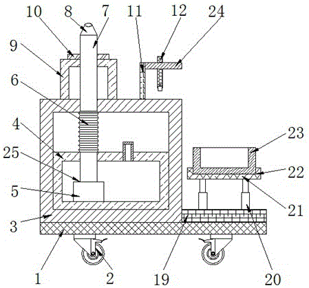
fig. 1 is a schematic structural view of the present invention.
Fig. 2 is a top view of fig. 1.
Fig. 3 is a sectional view taken along line a-a in fig. 2.
Fig. 4 is a schematic structural view of the work frame of the present invention.
Description of reference numerals:
base plate 1, universal wheel 2, processing case 3, disinfectant case 4, suction pump 5, conveyer pipe 6, connecting pipe 7, nozzle 8, support frame 9, limiting plate 10, fixed plate 11, work frame 12, installation pole 13, buckle 14, draw-in groove 15, magic tape thorn face 16, magic tape matte 17, disinfection piece 18, backup pad 19, electric telescopic handle 20, place seat 21, standing groove 22, hold box 23, place pole 24, spray rinsing mechanism 25.
The specific implementation mode is as follows:
the technical solutions in the embodiments of the present invention will be clearly and completely described below with reference to the drawings in the embodiments of the present invention, and it is obvious that the described embodiments are only a part of the embodiments of the present invention, and not all of the embodiments. All other embodiments, which can be obtained by a person skilled in the art without making any creative effort based on the embodiments in the present invention, belong to the protection scope of the present invention.
As shown in fig. 1 to 4, the following technical solutions are adopted in the present embodiment: the device comprises a base plate 1, universal wheels 2 and a treatment box 3, wherein the universal wheels 2 are rotatably arranged at four corners of the bottom of the base plate 1 through wheel seats, the treatment box 3 is fixedly riveted on the left side of the top surface of the base plate 1, and a sealing door is arranged on the front side of the treatment box 3;
it also includes:
the disinfectant tank 4 is riveted and fixed on the inner wall of the lower side of the treatment tank 3, and the upper side of the disinfectant tank 4 is connected with a liquid inlet pipe in a penetrating way;
the spray washing mechanism 25, the said spray washing mechanism 25 is set up in the inside of the disinfectant box 4;
the fixed plate 11 is riveted and fixed on the right side of the top surface of the treatment box 3;
the placing rod 24, the placing rod 24 is riveted and fixed on the right side of the fixing plate 11;
the working frame 12 is erected on the placing rod 24, and the working frame 12 is arranged in an inverted U-shaped structure;
the mounting rods 13 are inserted into the vertical rods on the front side and the rear side of the working frame 12;
the two buckles 14 are respectively riveted and fixed on the front side and the rear side of the top surface of the mounting rod 13, and the buckles 14 are respectively clamped in clamping grooves 15 formed in the vertical rods on the front side and the rear side of the working frame 12;
the magic tape stabbing surface 16 is sewn and fixed at the lower side of the mounting rod 13;
the sterilizing sheet 18 is arranged at the lower side of the mounting rod 13, a magic tape burr surface 17 is sewn and fixed at the upper side of the sterilizing sheet 18, and the magic tape burr surface 17 is adhered with the magic tape stabbing surface 16;
the supporting plate 19 is riveted and fixed on the right side of the top surface of the substrate 1, and the supporting plate 19 is arranged on the right side of the treatment box 3;
the two electric telescopic rods 20 are respectively riveted and fixed on the top surface of the supporting plate 19 in a bilateral symmetry manner, and the electric telescopic rods 20 are connected with an external power supply;
the placing seat 21, the placing seat 21 is riveted and fixed on the output end of the electric telescopic rod 20;
a containing box 23, wherein the containing box 23 is arranged at the upper side of the placing seat 21.
Preferably, the spray mechanism 25 further includes:
the suction pump 5 is riveted and fixed on the inner wall of the lower side of the disinfectant tank 4, and the suction pump 5 is connected with an external power supply;
the lower end of the conveying pipe 6 is communicated with the water outlet of the suction pump 5, and the upper end of the conveying pipe 6 penetrates through the upper side wall of the disinfectant tank 4 and then is arranged above the disinfectant tank 4;
and the connecting pipe 7 is in through connection with the upper end of the conveying pipe 6, and the upper end of the connecting pipe 7 is in through connection with a nozzle 8 after penetrating through the upper side wall of the treatment box 3.
As preferred scheme, still further, riveting fixed has support frame 9 on the top surface of handling case 3, and support frame 9 sets up for "U" shape structure, and in support frame 9 was worn to locate by connecting pipe 7, fixed cover was equipped with limiting plate 10 on the periphery wall of connecting pipe 7, and limiting plate 10 sets up on the top surface of support frame 9.
Further, preferably, the placing seat 21 is opened with a placing groove 22 therein, and the housing box 23 is disposed in the placing groove 22.
The working principle of the specific implementation mode is as follows: when the device is used, the disinfectant tank 4 is moved to the side of a patient by using the universal wheel 2, then the suction pump 5 is started, the suction pump 5 pumps disinfectant, the disinfectant is sprayed out from the nozzle 8 after passing through the delivery pipe 6 and the connecting pipe 7, a medical worker pulls out the connecting pipe 7, and the nozzle 8 is aligned to a wound for cleaning;
when needs dip in and get the antiseptic solution, at first dip in the height of getting sterile wound as required, utilize electric telescopic handle 20 to adjust the height that holds box 23, then medical personnel sprays the liquid of nozzle 8 to holding box 23 in, take off work frame 12, dip in disinfection piece 18 and get the antiseptic solution and clear up, the clearance disinfection finishes, will install pole 13 and take out, buckle 14 breaks away from draw-in groove 15, and make magic subsides thorn face 16 and the separation of magic subsides matte 17, take off disinfection piece 18.
After adopting above-mentioned structure, this embodiment's beneficial effect is as follows:
1. the installation rod 13 and the buckle 14 are arranged, so that the installation rod 13 and the disinfection sheet 18 can be conveniently taken down and cleaned after cleaning is finished, and the cleaning effect is improved;
2. the suction pump 5, the conveying pipe 6 and the nozzle 8 are arranged, and the conveying pipe 6 can be stretched according to requirements, so that the cleaning range of the nozzle 8 is expanded;
3. a placing groove 22 is arranged to facilitate taking out and cleaning the containing box 23 from the placing seat 21.
Although the present invention has been described in detail with reference to the foregoing embodiments, it will be apparent to those skilled in the art that modifications may be made to the embodiments described in the foregoing embodiments, or equivalents may be substituted for elements thereof.