CN216929751U - A dilatation protection casing for mine motor - Google Patents
A dilatation protection casing for mine motor Download PDFInfo
- Publication number
- CN216929751U CN216929751U CN202123366159.XU CN202123366159U CN216929751U CN 216929751 U CN216929751 U CN 216929751U CN 202123366159 U CN202123366159 U CN 202123366159U CN 216929751 U CN216929751 U CN 216929751U
- Authority
- CN
- China
- Prior art keywords
- housing
- plate
- protection
- liquid push
- push rods
- Prior art date
- Legal status (The legal status is an assumption and is not a legal conclusion. Google has not performed a legal analysis and makes no representation as to the accuracy of the status listed.)
- Active
Links
Images

Classifications
-
- Y—GENERAL TAGGING OF NEW TECHNOLOGICAL DEVELOPMENTS; GENERAL TAGGING OF CROSS-SECTIONAL TECHNOLOGIES SPANNING OVER SEVERAL SECTIONS OF THE IPC; TECHNICAL SUBJECTS COVERED BY FORMER USPC CROSS-REFERENCE ART COLLECTIONS [XRACs] AND DIGESTS
- Y02—TECHNOLOGIES OR APPLICATIONS FOR MITIGATION OR ADAPTATION AGAINST CLIMATE CHANGE
- Y02T—CLIMATE CHANGE MITIGATION TECHNOLOGIES RELATED TO TRANSPORTATION
- Y02T10/00—Road transport of goods or passengers
- Y02T10/60—Other road transportation technologies with climate change mitigation effect
- Y02T10/64—Electric machine technologies in electromobility
Abstract
The utility model discloses a dilatation protective cover for a mine motor, which belongs to the technical field of protective covers and adopts the technical scheme that the dilatation protective cover comprises a bottom plate, wherein a driving motor is arranged on the rear end surface of a mounting plate, the output end of the driving motor is detachably connected with a rotating shaft, the rear end of the rotating shaft penetrates through a cover shell and extends to the rear part of the cover shell, and the rear end surface of the cover shell penetrates through a sealing bearing matched with the rotating shaft; two second electricity liquid push rods are all installed to the one end that fixed riser carried on the back mutually, and the other end of four two liang of vertical second electricity liquid push rods that distribute side by side all installs and adjusts the protection curb plate, connect the up end of diaphragm and install two first electricity liquid push rods, the both sides fixedly connected with arc guard plate of fixed diaphragm to do not influence the leakproofness of housing to driving motor when this protection casing adjusts the size of protection space, prevent to get into the problem in the housing under the mine environment to dust and ore granule etc. in the big or small accommodation process of protection space.
Description
Technical Field
The utility model relates to the technical field of protective covers, in particular to a dilatation protective cover for a mine motor.
Background
The motor is an electromagnetic device for realizing electric energy conversion or transmission according to an electromagnetic induction law, and has the main functions of converting mechanical energy into electric energy to generate driving torque to serve as a power source of electrical appliances or various machines.
The dilatation protection casing that is used for mine motor that has now causes the influence to the leakproofness of housing when adjusting the size in protection space easily, and in getting into the housing to dust and ore granule etc. in the size accommodation process of protection space under the mine environment, and then causes the influence to driving motor's operation, reduces driving motor's life.
SUMMERY OF THE UTILITY MODEL
The utility model provides a dilatation protective cover for a mine motor to solve the problems.
The utility model is realized in this way, the capacity-expanding protective cover for the mine motor comprises a bottom plate, wherein a cover casing is arranged on the upper end surface of the bottom plate, a connecting transverse plate is fixedly connected inside the cover casing, two fixing vertical plates are fixedly connected to the lower end surface of the connecting transverse plate, a mounting plate is fixedly connected between the two fixing vertical plates, the upper end surface of the mounting plate is fixedly connected with the lower end surface of the connecting transverse plate, a driving motor is arranged on the rear end surface of the mounting plate, a rotating shaft is detachably connected to the output end of the driving motor, the rear end of the rotating shaft penetrates through the cover casing and extends to the rear of the cover casing, and a sealing bearing matched with the rotating shaft is connected to the rear end surface of the cover casing in a penetrating manner;
two second electricity liquid push rods are all installed to the one end that fixed riser carried on the back mutually, and four second electricity liquid push rods's the other end all runs through the housing and extends to the outside of housing, and four two liang of vertical second electricity liquid push rods that distribute side by side's the other end all installs and adjusts the protection curb plate, two first electricity liquid push rods are installed to the up end of connecting the diaphragm, two the upper end of first electricity liquid push rod all runs through the housing and extends to the top of housing, two fixed diaphragm is installed to the up end of first electricity liquid push rod, the both sides fixedly connected with arc guard plate of fixed diaphragm.
In order to utilize the driving motor to automatically drive the fan blades to rotate so as to discharge the heat generated by the fan blades and solve the problem of increased energy consumption caused by the increase of heat dissipation of a small suction fan in the conventional device, the expansion protection cover for the mine motor is preferably used.
In order to achieve the buffer protection effect on the arc-shaped protection plate and the two adjusting protection side plates when ore particles and the like fall onto the outer walls of the arc-shaped protection plate and the two adjusting protection side plates, the expansion protection cover for the mine motor is preferably used as the expansion protection cover for the mine motor, and the outer side walls of the arc-shaped protection plate and the two adjusting protection side plates are fixedly connected with rubber pads.
In order to facilitate maintenance and replacement of the driving motor, the expansion protection cover for the mine motor is preferably used, the outer side wall of the cover casing is fixedly connected with a connecting frame, and the connecting frame is detachably connected with the bottom plate through a plurality of bolts.
In order to facilitate installation of the protective cover and corresponding equipment, the expansion protective cover for the mine motor is preferably used, and four uniformly distributed installation holes are formed in the upper end face of the bottom plate in a penetrating mode.
In order to support and fix the mounting plate and the two fixed vertical plates, the lower end surfaces of the mounting plate and the two fixed vertical plates are tightly attached to the upper end surface of the bottom plate, and the mounting plate and the two fixed vertical plates are preferably used as the expansion protection cover for the mine motor.
Compared with the prior art, the utility model has the beneficial effects that:
this kind of an dilatation protection casing for mine motor, this driving motor installs on the mounting panel in the housing, the pivot passes sealed bearing and extends outside the housing, when adjusting the protective space of this protection casing, open two first electric liquid push rods and four second electric liquid push rods simultaneously, two first electric liquid push rods and four second electric liquid push rods drive arc guard plate and two inside and outside removal of regulation protective side board respectively, change protective space's size, thereby do not influence the leakproofness of housing to driving motor when this protection casing adjusts protective space's size, prevent under the mine environment to the problem in protective space size accommodation process dust and ore granule etc. get into the housing.
Drawings
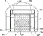
FIG. 1 is a cross-sectional view of an expansion shield for a mine motor of the present invention;
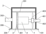
FIG. 2 is a right sectional view of an expansion shield for a mine motor of the present invention;
fig. 3 is a structural view of an arc guard of the present invention.
In the figure, 1, a bottom plate; 101. mounting holes; 2. a housing; 201. connecting the transverse plates; 202. fixing a vertical plate; 203. a radiating pipe; 204. a connecting frame; 205. a bolt; 3. mounting a plate; 301. opening a hole; 4. a drive motor; 401. a rotating shaft; 402. sealing the bearing; 403. a fan blade; 5. a first electro-hydraulic push rod; 501. fixing the transverse plate; 502. an arc-shaped protection plate; 503. a second electro-hydraulic push rod; 504. adjusting the protective side plate; 505. and (7) a rubber pad.
Detailed Description
In order to make the objects, technical solutions and advantages of the present invention more apparent, the present invention is described in further detail below with reference to the accompanying drawings and embodiments. It should be understood that the specific embodiments described herein are merely illustrative of the utility model and are not intended to limit the utility model.
In the description of the present invention, it is to be understood that the terms "length", "width", "upper", "lower", "front", "rear", "left", "right", "vertical", "horizontal", "top", "bottom", "inner", "outer", and the like, indicate orientations or positional relationships based on the orientations or positional relationships illustrated in the drawings, and are used merely for convenience in describing the present invention and for simplicity in description, and do not indicate or imply that the devices or elements referred to must have a particular orientation, be constructed in a particular orientation, and be operated, and thus, are not to be construed as limiting the present invention. Further, in the description of the present invention, "a plurality" means two or more unless specifically defined otherwise.
Referring to fig. 1-3, an expansion shield for a mine motor comprises a base plate 1, a housing 2 is mounted on the upper end surface of the base plate 1, a connecting transverse plate 201 is fixedly connected inside the housing 2, two fixing vertical plates 202 are fixedly connected to the lower end surface of the connecting transverse plate 201, a mounting plate 3 is fixedly connected between the two fixing vertical plates 202, the upper end surface of the mounting plate 3 is fixedly connected with the lower end surface of the connecting transverse plate 201, a driving motor 4 is mounted on the rear end surface of the mounting plate 3, an output end of the driving motor 4 is detachably connected with a rotating shaft 401, the rear end of the rotating shaft 401 penetrates through the housing 2 and extends to the rear of the housing 2, and a sealing bearing 402 matched with the rotating shaft 401 is connected to the rear end surface of the housing 2 in a penetrating manner;
two second electricity liquid push rods 503 are all installed to the one end that two fixed risers 202 carried on the back mutually, four second electricity liquid push rods 503's the other end all runs through housing 2 and extends to the outside of housing 2, four two liang of vertical second electricity liquid push rods 503's that distribute side by side other end all installs and adjusts protection curb plate 504, two first electricity liquid push rods 5 are installed to the up end of connecting diaphragm 201, housing 2 and the top that extends to housing 2 are all run through to the upper end of two first electricity liquid push rods 5, fixed diaphragm 501 is installed to the up end of two first electricity liquid push rods 5, fixed diaphragm 501's both sides fixedly connected with arc guard plate 502.
In this embodiment: this driving motor 4 installs on the mounting panel 3 in housing 2, pivot 401 passes sealed bearing 402 and extends outside housing 2, when adjusting the protection space of this protection casing, open two first electricity liquid push rods 5 and four second electricity liquid push rods 503 simultaneously, two first electricity liquid push rods 5 and four second electricity liquid push rods 503 drive arc guard plate 502 and two regulation protection curb plate 504 inside and outside removal respectively, change protection space's size, thereby do not influence the leakproofness of housing 2 to driving motor 4 when this protection casing adjusts protection space's size, prevent under the mine environment to get into the problem in the housing 2 to protection space size adjustment in-process dust and ore granule etc..
As a technical optimization scheme of the utility model, a plurality of openings 301 are formed in the front end surface of the mounting plate 3 in a penetrating manner, fan blades 403 are arranged on the outer side wall of a rotating shaft 401 positioned in the housing 2, and the front end surface of the housing 2 is communicated with a radiating pipe 203.
In this embodiment: in the operation process of the driving motor 4, the rotating shaft 401 drives the fan blades 403 to be located in the housing 2 to rotate, heat generated by the operation of the driving motor 4 in the housing 2 is blown out forwards through the plurality of openings 301 and is discharged through the radiating pipe 203, so that the driving motor 4 is utilized to automatically drive the fan blades 403 to rotate to discharge heat generated by the fan blades, and the problem that the energy consumption is increased due to the fact that the existing device dissipates heat through the addition of a small suction fan is solved.
As a technical optimization scheme of the utility model, the outer side walls of the arc-shaped protection plate 502 and the two adjusting protection side plates 504 are fixedly connected with rubber pads 505.
In this embodiment: when ore particles and the like fall to the outer walls of the arc-shaped protection plate 502 and the two adjusting protection side plates 504, the rubber pads 505 play a role in buffering and protecting the arc-shaped protection plate 502 and the two adjusting protection side plates 504.
As a technical optimization scheme of the utility model, the outer side wall of the housing 2 is fixedly connected with a connecting frame 204, and the connecting frame 204 is detachably connected with the bottom plate 1 through a plurality of bolts 205.
In this embodiment: when the driving motor 4 in the housing 2 is maintained and replaced, the bolts 205 are screwed and disassembled to separate the bottom plate 1 from the housing 2, and then the driving motor 4 in the housing 2 is maintained and replaced, so that the effect of conveniently maintaining and replacing the driving motor 4 is achieved.
As a technical optimization scheme of the utility model, four uniformly distributed mounting holes 101 are formed in the upper end surface of the bottom plate 1 in a penetrating manner.
In this embodiment: when the protective cover is installed on corresponding equipment, screws are screwed into the four installation holes 101, so that the protective cover is connected with the corresponding equipment, and the protective cover is conveniently installed on the corresponding equipment.
As a technical optimization scheme of the utility model, the lower end surfaces of the mounting plate 3 and the two fixed vertical plates 202 are tightly attached to the upper end surface of the bottom plate 1.
In this embodiment: the lower terminal surface through mounting panel 3 and two fixed risers 202 all closely laminates with the up end of bottom plate 1, and then bottom plate 1 plays the fixed effect of support to mounting panel 3 and two fixed risers 202.
The working principle and the using process of the utility model are as follows: the driving motor 4 is installed on the installation plate 3 in the housing 2, the rotating shaft 401 passes through the sealed bearing 402 and extends out of the housing 2, when the protection space of the protective cover is adjusted, two first electro-hydraulic push rods 5 and four second electro-hydraulic push rods 503 are simultaneously opened, the two first electro-hydraulic push rods 5 and the four second electro-hydraulic push rods 503 respectively drive the arc-shaped protection plate 502 and the two adjusting protection side plates 504 to move inside and outside, the size of the protection space is changed, when ore particles and the like fall on the outer walls of the arc-shaped protection plate 502 and the two adjusting protection side plates 504, the arc-shaped protection plate 502 and the two adjusting protection side plates 504 are buffered and protected through the rubber pads 505, during the operation process of the driving motor 4, the rotating shaft 401 drives the fan blades 403 to rotate in the housing 2, heat generated by the operation of the driving motor 4 in the housing 2 is blown out through the plurality of openings 301 forward and is discharged through the radiating pipe 203, when the drive motor 4 in the housing 2 is to be repaired or replaced, the plurality of bolts 205 are screwed and removed to separate the base plate 1 from the housing 2, and then the drive motor 4 in the housing 2 is repaired or replaced.
The present invention is not limited to the above preferred embodiments, and any modifications, equivalent substitutions and improvements made within the spirit and principle of the present invention should be included in the protection scope of the present invention.
Claims (6)
1. The utility model provides a dilatation protection casing for mine motor which characterized in that includes:
the improved structure of the automobile seat is characterized by comprising a base plate (1), a housing (2) is installed on the upper end face of the base plate (1), a connecting transverse plate (201) is fixedly connected to the inside of the housing (2), two fixing vertical plates (202) are fixedly connected to the lower end face of the connecting transverse plate (201), a mounting plate (3) is fixedly connected between the two fixing vertical plates (202), the upper end face of the mounting plate (3) is fixedly connected with the lower end face of the connecting transverse plate (201), a driving motor (4) is installed on the rear end face of the mounting plate (3), a rotating shaft (401) is detachably connected to the output end of the driving motor (4), the rear end of the rotating shaft (401) penetrates through the housing (2) and extends to the rear of the housing (2), and a sealing bearing (402) matched with the rotating shaft (401) is connected to the rear end face of the housing (2) in a penetrating manner;
two fixed riser (202) one end of carrying on the back mutually all installs two second electricity liquid push rods (503), and the other end of four second electricity liquid push rods (503) all runs through housing (2) and extends to the outside of housing (2), and four two liang of vertical second electricity liquid push rods (503) that distribute side by side all install and adjust protection curb plate (504), connect the up end of diaphragm (201) and install two first electricity liquid push rods (5), two the top of housing (2) and extending to housing (2) is all run through to the upper end of first electricity liquid push rod (5), two fixed diaphragm (501) are installed to the up end of first electricity liquid push rod (5), the both sides fixedly connected with arc guard plate (502) of fixed diaphragm (501).
2. The capacity expansion shield for the mine motor of claim 1, wherein: the preceding terminal surface of mounting panel (3) runs through and has seted up a plurality of trompils (301), and flabellum (403) are installed to the lateral wall that is located pivot (401) in housing (2), the preceding terminal surface intercommunication of housing (2) has cooling tube (203).
3. The capacity expansion shield for the mine motor of claim 1, wherein: the outer side walls of the arc-shaped protection plate (502) and the two adjusting protection side plates (504) are fixedly connected with rubber pads (505).
4. The capacity expansion shield for the mine motor of claim 1, wherein: the outer side wall of the housing (2) is fixedly connected with a connecting frame (204), and the connecting frame (204) is detachably connected with the bottom plate (1) through a plurality of bolts (205).
5. The capacity expansion shield for the mine motor of claim 1, wherein: four evenly distributed mounting holes (101) are formed in the upper end face of the bottom plate (1) in a penetrating mode.
6. The capacity expansion shield for the mine motor of claim 1, wherein: the lower end faces of the mounting plate (3) and the two fixed vertical plates (202) are tightly attached to the upper end face of the bottom plate (1).
Priority Applications (1)
| Application Number | Priority Date | Filing Date | Title |
|---|---|---|---|
| CN202123366159.XU CN216929751U (en) | 2021-12-29 | 2021-12-29 | A dilatation protection casing for mine motor |
Applications Claiming Priority (1)
| Application Number | Priority Date | Filing Date | Title |
|---|---|---|---|
| CN202123366159.XU CN216929751U (en) | 2021-12-29 | 2021-12-29 | A dilatation protection casing for mine motor |
Publications (1)
| Publication Number | Publication Date |
|---|---|
| CN216929751U true CN216929751U (en) | 2022-07-08 |
Family
ID=82254071
Family Applications (1)
| Application Number | Title | Priority Date | Filing Date |
|---|---|---|---|
| CN202123366159.XU Active CN216929751U (en) | 2021-12-29 | 2021-12-29 | A dilatation protection casing for mine motor |
Country Status (1)
| Country | Link |
|---|---|
| CN (1) | CN216929751U (en) |
-
2021
- 2021-12-29 CN CN202123366159.XU patent/CN216929751U/en active Active
Similar Documents
| Publication | Publication Date | Title |
|---|---|---|
| CN110332417A (en) | Diesel engine type uninterruptible power supply | |
| CN210142301U (en) | High heat dissipating's main frame machine case | |
| CN216929751U (en) | A dilatation protection casing for mine motor | |
| CN208190403U (en) | A kind of stepper motor shell of high efficiency and heat radiation | |
| CN108995606A (en) | A kind of vehicle-carrying display screen damping | |
| CN213044044U (en) | Speed regulating system of alternating current motor of electric automobile | |
| CN109217134B (en) | Electric power regulation and control switchboard equipment protection device with dustproof heat dissipation function | |
| CN209929723U (en) | Suspension type is convenient for high-low voltage regulator cubicle of adjusting | |
| CN217880219U (en) | Integrated monitoring host | |
| CN220231820U (en) | Electronic instrument detection box with heat dissipation function for automatic electrified engineering | |
| CN215733035U (en) | AGC performance device | |
| CN219499894U (en) | UPS power supply heat abstractor | |
| CN220291466U (en) | Heat radiation structure of electric control cabinet | |
| CN219887023U (en) | Hydraulic engineering pump station protector | |
| CN212627543U (en) | Anti-interference structure for permanent magnet synchronous motor | |
| CN213783080U (en) | Speed reduction motor with automatic overload power-off protection function | |
| CN220527399U (en) | Efficient and energy-saving device of electric power system convenient to install and detach | |
| CN220646313U (en) | Centrifugal pump convenient to install | |
| CN212061105U (en) | CPU cooling fan | |
| CN215148513U (en) | Clamping device is used in installation of motorcycle type frame | |
| CN213754448U (en) | Radio frequency power amplifier convenient to installation is dismantled | |
| CN219042346U (en) | Frequency conversion plate heat radiation structure of air source heat pump unit | |
| CN220190663U (en) | Base support for frequency converter of mechanical equipment | |
| CN220544783U (en) | Base for motor installation | |
| CN219745167U (en) | High-efficient radiating dish formula separating centrifuge heat abstractor |
Legal Events
| Date | Code | Title | Description |
|---|---|---|---|
| GR01 | Patent grant | ||
| GR01 | Patent grant |