CN216917841U - Material blocking tripod - Google Patents
Material blocking tripod Download PDFInfo
- Publication number
- CN216917841U CN216917841U CN202220737869.4U CN202220737869U CN216917841U CN 216917841 U CN216917841 U CN 216917841U CN 202220737869 U CN202220737869 U CN 202220737869U CN 216917841 U CN216917841 U CN 216917841U
- Authority
- CN
- China
- Prior art keywords
- rod
- rectangular frame
- sliding
- stock
- sliding groove
- Prior art date
- Legal status (The legal status is an assumption and is not a legal conclusion. Google has not performed a legal analysis and makes no representation as to the accuracy of the status listed.)
- Expired - Fee Related
Links
- 230000000903 blocking effect Effects 0.000 title claims abstract description 27
- 239000000463 material Substances 0.000 title claims abstract description 27
- 230000000712 assembly Effects 0.000 claims description 6
- 238000000429 assembly Methods 0.000 claims description 6
- 238000010276 construction Methods 0.000 abstract description 2
- 239000002689 soil Substances 0.000 description 6
- 239000004575 stone Substances 0.000 description 4
- 230000000694 effects Effects 0.000 description 3
- 230000004888 barrier function Effects 0.000 description 2
- 230000004048 modification Effects 0.000 description 2
- 238000012986 modification Methods 0.000 description 2
- 230000009286 beneficial effect Effects 0.000 description 1
- 230000008859 change Effects 0.000 description 1
- 230000006872 improvement Effects 0.000 description 1
Images


Landscapes
- Refuge Islands, Traffic Blockers, Or Guard Fence (AREA)
Abstract
The utility model provides a material blocking tripod and relates to the technical field of construction devices. A material blocking tripod comprises two right-angle frames, a rectangular frame is arranged between the two right-angle frames, a baffle is detachably arranged on the rectangular frame, the rectangular frame comprises two longitudinal support rods and two transverse support rods, the two transverse support rods are obliquely connected to the two right-angle frames, and the two transverse support rods are telescopic rods; the triangular rubber can adjust the width and the height of the triangular rubber, is suitable for more occasions, is more convenient to use, and can realize the function of stopping materials stably.
Description
Technical Field
The utility model relates to the technical field of construction devices, in particular to a material blocking tripod.
Background
When a loading vehicle for loading soil or stone unloads the soil or stone thereon, a material blocking tripod is often placed around the loading vehicle for preventing the soil or stone from scattering to the outside, so that the soil or stone is piled together as much as possible, but the existing material blocking tripod is only in a fixed shape and cannot be applied to various material blocking environments, and the loading vehicle is inconvenient to use and the problem is urgently needed to be solved.
SUMMERY OF THE UTILITY MODEL
The utility model aims to provide a material blocking tripod, which can adjust the width and the height of the material blocking tripod, is suitable for more occasions, is more convenient to use and can realize the material blocking function stably.
The embodiment of the utility model is realized by the following steps:
the embodiment of the application provides a keep off material tripod, including two right angle framves, be provided with rectangular frame between two above-mentioned right angle framves, the last baffle that can dismantle of above-mentioned rectangular frame, above-mentioned rectangular frame includes two longitudinal support pole and two horizontal bracing pieces, and two above-mentioned horizontal bracing pieces slope is connected on two above-mentioned right angle framves, and two above-mentioned horizontal bracing pieces are the telescopic link.
In some embodiments of the present invention, each of the two transverse support rods includes a first connection rod and a second connection rod, a sliding hole is disposed on an end surface of the first connection rod close to the second connection rod, a sliding rod is disposed on an end portion of the second connection rod close to the first connection rod, the sliding rod is slidably disposed in the sliding hole, a first threaded hole is disposed on an outer side wall of the first connection rod, the first threaded hole is communicated with the sliding hole, and a first fixing member is disposed on the first threaded hole.
In some embodiments of the present invention, the first connecting rod includes a first connecting rod body and a plurality of first placing plates, the second connecting rod includes a second connecting rod body and a plurality of second placing plates, and the first placing plates and the second placing plates have the same structure.
In some embodiments of the present invention, each of the right-angle brackets includes a longitudinal rod and a vertical rod, a lateral sliding groove is formed on a side wall of each of the two longitudinal rods, and a vertical sliding groove is formed on each of the two vertical rods; the two longitudinal support rods are hinged with a first sliding part and a second sliding part, the first sliding part is arranged in the transverse sliding groove in a sliding manner, and the second sliding part is arranged in the vertical sliding groove in a sliding manner; and a second threaded hole is formed in the second sliding part, and a second fixing piece is connected to the second threaded hole in a threaded mode.
In some embodiments of the present invention, the rectangular frame is disposed between two of the right-angle brackets, any one of the horizontal sliding grooves is disposed on a side wall of the vertical rod where the horizontal sliding groove is located, which is close to the longitudinal supporting rod, and any one of the vertical sliding grooves is disposed on a side wall of the vertical rod where the vertical sliding groove is located, which is close to the longitudinal supporting rod.
In some embodiments of the present invention, the lower ends of the two transverse support rods below the two transverse support rods are provided with elastic blocking pads.
In some embodiments of the utility model, the length of the resilient barrier pad is the same as the length of the lateral support bar.
In some embodiments of the present invention, the elastic blocking pad is a rubber pad.
In some embodiments of the utility model, a plurality of moving assemblies are provided at the lower end of any one of the right-angled frames.
In some embodiments of the utility model, any of the moving assemblies is a universal wheel.
Compared with the prior art, the embodiment of the utility model has at least the following advantages or beneficial effects:
the utility model provides a keep off material tripod, includes two right angle framves, is provided with rectangular frame between two above-mentioned right angle framves, can dismantle on the above-mentioned rectangular frame and be equipped with the baffle, and above-mentioned rectangular frame includes two longitudinal support pole and two horizontal bracing pieces, and two above-mentioned horizontal bracing pieces slope is connected on two above-mentioned right angle framves, and two above-mentioned horizontal bracing pieces are the telescopic link.
Two right-angle stands are used for fixed rectangular frame, the baffle can be dismantled and establish on rectangular frame, because rectangular frame includes two longitudinal support pole and two horizontal bracing pieces, two horizontal bracing pieces are the telescopic link, thereby two horizontal bracing pieces can transversely extend or shorten, thereby make whole rectangular frame's horizontal length can grow or shorten, thereby whole length of keeping off the material tripod can the length of side or shorten, thereby can be applicable to different occasions, and be used for keeping off the material, convenient to use person uses, and the baffle can be the baffle of different models, when rectangular frame's size change, the baffle size changes along with it, thereby place on rectangular frame, keep off the material better.
Drawings
In order to more clearly illustrate the technical solutions of the embodiments of the present invention, the drawings needed to be used in the embodiments will be briefly described below, it should be understood that the following drawings only illustrate some embodiments of the present invention and therefore should not be considered as limiting the scope, and for those skilled in the art, other related drawings can be obtained according to the drawings without inventive efforts.
FIG. 1 is a schematic view of the overall front (with baffles removed) configuration of the present invention;
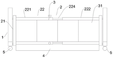
FIG. 2 is a schematic view of the overall front structure of the present invention;
FIG. 3 is a schematic view of the structure of the longitudinal support rod and the right-angle stand of the present invention.
Icon: 1-right-angle frame, 11-longitudinal rod, 12-vertical rod, 13-transverse sliding groove, 14-vertical sliding groove, 2-rectangular frame, 21-longitudinal supporting rod, 22-transverse supporting rod, 221-first connecting rod body, 222-second connecting rod body, 223-sliding hole, 224-sliding rod, 225-first fixing piece, 226-first placing plate, 227-second placing plate, 23-first sliding portion, 24-second sliding portion, 25-second fixing piece, 3-baffle plate, 31-mounting plate, 4-elastic blocking pad and 5-universal wheel.
Detailed Description
In order to make the objects, technical solutions and advantages of the embodiments of the present invention clearer, the technical solutions in the embodiments of the present invention will be clearly and completely described below with reference to the drawings in the embodiments of the present invention, and it is obvious that the described embodiments are some, but not all, embodiments of the present invention. The components of embodiments of the present invention generally described and illustrated in the figures herein may be arranged and designed in a wide variety of different configurations.
Thus, the following detailed description of the embodiments of the present invention, presented in the figures, is not intended to limit the scope of the utility model, as claimed, but is merely representative of selected embodiments of the utility model. All other embodiments, which can be derived by a person skilled in the art from the embodiments given herein without making any creative effort, shall fall within the protection scope of the present invention.
It should be noted that: like reference numbers and letters refer to like items in the following figures, and thus, once an item is defined in one figure, it need not be further defined and explained in subsequent figures.
In the description of the embodiments of the present invention, it should be noted that, if the terms "center", "upper", "lower", "left", "right", "vertical", "horizontal", "inner", "outer", etc. indicate an orientation or a positional relationship based on the orientation or the positional relationship shown in the drawings, or an orientation or a positional relationship which is usually placed when the products of the present invention are used, the description is only for convenience and simplicity, and the indication or the suggestion that the referred device or element must have a specific orientation, be constructed in a specific orientation, and be operated, and thus, the present invention should not be construed as being limited. Furthermore, the terms "first," "second," and the like are used merely to distinguish one description from another, and are not to be construed as indicating or implying relative importance.
Furthermore, the terms "horizontal", "vertical", "overhang" and the like do not require that the components be absolutely horizontal or overhang, but may be slightly inclined. For example, "horizontal" merely means that the direction is more horizontal than "vertical" and does not mean that the structure must be perfectly horizontal, but may be slightly inclined.
In the description of the embodiments of the present invention, "a plurality" represents at least 2.
In the description of the embodiments of the present invention, it should be further noted that unless otherwise explicitly stated or limited, the terms "disposed," "mounted," "connected," and "connected" should be interpreted broadly, and may be, for example, fixedly connected, detachably connected, or integrally connected; can be mechanically or electrically connected; they may be connected directly or indirectly through intervening media, or they may be interconnected between two elements. The specific meanings of the above terms in the present invention can be understood by those skilled in the art according to specific situations.
Example 1
As shown in fig. 1, this embodiment provides a keep off material tripod, including two right-angle stands 1, be provided with rectangular frame 2 between two above-mentioned right-angle stands 1, above-mentioned rectangular frame 2 is last to dismantle and is equipped with baffle 3, and above-mentioned rectangular frame 2 includes two longitudinal support rods 21 and two horizontal support rods 22, and two above-mentioned horizontal support rods 22 slope is connected on two above-mentioned right-angle stands 1, and two above-mentioned horizontal support rods 22 are the telescopic link.
In this embodiment, two right-angle stands 1 are used for fixed rectangular frame 2, baffle 3 can be dismantled and establish on rectangular frame 2, because rectangular frame 2 includes two longitudinal support pole 21 and two horizontal bracing piece 22, two horizontal bracing piece 22 are the telescopic link, but two horizontal bracing piece 22 horizontal extension perhaps shorten, thereby make whole rectangular frame 2's horizontal length can grow or shorten, thereby whole length that keeps off the material tripod can the length of side or shorten, thereby can be applicable to different occasions, and be used for keeping off the material, convenient to use person uses, and baffle 3 that baffle 3 can be different models, when rectangular frame 2's size changes, baffle 3's size changes thereupon, thereby place on rectangular frame 2, keep off the material better.
Specifically, baffle 3 can constitute for polylith mounting panel 31, through the number that increases or reduce the plank to the length of adjustment baffle 3, thereby the better size that is applicable to rectangular frame 2, the better effect that realizes keeping off the material.
Example 2
As shown in fig. 1 to 3, in this embodiment, in addition to embodiment 1, each of the two transverse support bars 22 includes a first connection bar and a second connection bar, a sliding hole 223 is formed on an end surface of the first connection bar close to the second connection bar, a sliding bar 224 is arranged on an end portion of the second connection bar close to the first connection bar, the sliding bar 224 is slidably arranged in the sliding hole 223, a first threaded hole is formed on an outer side wall of the first connection bar, the first threaded hole is communicated with the sliding hole 223, and a first fixing member 225 is arranged on the first threaded hole.
In this embodiment, be provided with slide opening 223 on the head rod, slide bar 224 on the second connecting rod slides in slide opening 223, through making slide bar 224 slide in slide opening 223, when slide opening 223 slides to the position that the user needs, through first mounting 225 at first screw hole internal rotation, thereby fixed slide bar 224, make slide bar 224 not slide, thereby indirectly make the length of second connecting rod increase, two slide bars 224 slide simultaneously, thereby the length of two second connecting rods increases or shortens, the length of whole rectangular frame 2 changes, obtain the length that the user needs, thereby use, and is more convenient.
Specifically, the first fixing member 225 is a bolt, so that the cost is low, the using effect is good, and the replaceability is good.
In some embodiments of the present invention, the first connecting rod includes a first connecting rod body 221 and a plurality of first placing plates 226, the second connecting rod includes a second connecting rod body 222 and a plurality of second placing plates 227, and the first placing plates 226 and the second placing plates 227 have the same structure.
In the above embodiment, the plurality of first placing plates 226 and the plurality of second placing plates 227 are used for placing the baffle 3, two first placing plates 226 arranged in an up-down symmetrical manner constitute a first placing plate group, two second placing plates 227 arranged in an up-down symmetrical manner constitute a second placing plate group, and the plurality of mounting plates 31 constituting the baffle 3 are placed in the plurality of first placing plate groups and the plurality of second placing plate groups in this order, which is simple and convenient.
Specifically, the first board 226 and the second board 227 of placing are the L type and place the board to the mounting panel 31 can directly be placed on two upper and lower L type mounting panels 31, need not fix once more, and it is also more convenient to dismantle, and the user uses more conveniently.
Example 3
As shown in fig. 1 to 3, in this embodiment, on the basis of the above embodiments, each of the right-angle brackets 1 includes a vertical rod 11 and a vertical rod 12, a lateral sliding groove 13 is formed on a side wall of each of the two vertical rods 11, and a vertical sliding groove 14 is formed on each of the two vertical rods 12; a first sliding part 23 and a second sliding part 24 are hinged on the two longitudinal support rods 21, the first sliding part 23 is arranged in the transverse sliding groove 13 in a sliding manner, and the second sliding part 24 is arranged in the vertical sliding groove 14 in a sliding manner; and a second screw hole is formed in the second sliding portion 24, and a second fixing member 25 is threadedly coupled to the second screw hole.
In this embodiment, the horizontal sliding groove 13 and the vertical sliding groove 14 are provided, the first sliding portion 23 is slidably disposed in the horizontal sliding groove 13, the second sliding portion 24 is slidably disposed in the vertical sliding groove 14, and the first sliding portion 23 and the second sliding portion 24 are both hinged to the longitudinal support rod 21, so that the first sliding portion 23 and the second sliding portion 24 can be operated to respectively slide in the horizontal sliding groove 13 and the vertical sliding groove 14, the angle of the rectangular frame 2 can be adjusted by sliding the first sliding portion 23 and the second sliding portion 24, the height of the rectangular frame 2 is adjusted, the height of the baffle plate 3 mounted on the rectangular frame 2 can be increased, a user can use the rectangular frame 2 more conveniently by adjusting the height of the rectangular frame 2, and the baffle effect is better; after the height of the rectangular frame 2 is adjusted, the second fixing member 25 rotates in the threaded hole to fix the second sliding portion 24, so that the entire rectangular frame 2 can be fixed conveniently.
Specifically, the second fixing member 25 is a bolt, which is low in cost and good in replaceability.
In some embodiments of the present invention, the rectangular frame 2 is disposed between two of the right-angle brackets 1, any one of the horizontal sliding grooves 13 is disposed on the side wall of the vertical rod 11 near the longitudinal supporting rod 21, and any one of the vertical sliding grooves 14 is disposed on the side wall of the vertical rod 12 near the longitudinal supporting rod 21.
In the above embodiment, the horizontal sliding groove 13 and the vertical sliding groove 14 are disposed on the side wall of the right-angle frame 1 close to the rectangular frame 2, so that the first sliding portion 23 and the second sliding portion 24 can be conveniently installed, and the rectangular frame 2 is located between the two right-angle frames 1, so that the length and the height of the rectangular frame 2 can be conveniently adjusted.
Example 4
As shown in fig. 1-3, in this embodiment, on the basis of the above embodiments, the lower ends of the two transverse support rods 22 located below the two transverse support rods 22 are provided with elastic blocking pads 4.
In this embodiment, the elastic blocking pad 4 is located between the transverse support rod 22 and the ground, so as to prevent soil from scattering from a gap between the rectangular frame 2 and the ground, and ensure that the blocking effect of the whole blocking tripod is better.
In some embodiments of this embodiment, the length of the resilient barrier pad 4 is the same as the length of the lateral support bar 22.
In the above embodiment, the length of the elastic blocking pad 4 is the same as that of the transverse supporting rod 22, so that the gap between the transverse supporting rod 22 and the ground is completely closed, and the blocking effect is better.
In some embodiments of the present invention, the elastic blocking pad 4 is a rubber pad.
In the above embodiment, the elastic blocking pad 4 is a rubber pad, and the scattered soil can be ejected back by the elastic blocking pad 4, which is convenient.
In some embodiments of this embodiment, a plurality of moving assemblies are provided at the lower end of any one of the aforementioned right-angle stands 1.
In the above embodiment, the moving assembly enables the whole tripod to be moved conveniently, so that a user can use the tripod more conveniently, and the device can be moved to a position to be set conveniently.
In some embodiments of the present embodiment, any of the moving assemblies is a universal wheel 5.
In the above embodiment, the universal wheel 5 is convenient to move, and the universal wheel 5 is a commercially available product and has a long service life.
In summary, the embodiment of the utility model provides a material blocking tripod, which comprises two right-angle frames 1, a rectangular frame 2 is arranged between the two right-angle frames 1, a baffle 3 is detachably arranged on the rectangular frame 2, the rectangular frame 2 comprises two longitudinal support rods 21 and two transverse support rods 22, the two transverse support rods 22 are obliquely connected to the two right-angle frames 1, and the two transverse support rods 22 are telescopic rods.
Two right-angle stands 1 are used for fixed rectangular frame 2, baffle 3 can be dismantled and establish on rectangular frame 2, because rectangular frame 2 includes two longitudinal support pole 21 and two horizontal bracing piece 22, two horizontal bracing piece 22 are the telescopic link, thereby two horizontal bracing piece 22 can transversely extend or shorten, thereby make whole rectangular frame 2's horizontal length can grow or shorten, thereby whole length of keeping off the material tripod can the length of side or shorten, thereby can be applicable to different occasions, and be used for keeping off the material, convenient to use person uses, and baffle 3 can be the baffle 3 of different models, when rectangular frame 2's size changes, baffle 3's size changes thereupon, thereby place on rectangular frame 2, keep off the material better.
The above is only a preferred embodiment of the present invention, and is not intended to limit the present invention, and various modifications and changes will occur to those skilled in the art. Any modification, equivalent replacement, or improvement made within the spirit and principle of the present invention should be included in the protection scope of the present invention.
Claims (10)
1. The utility model provides a keep off material tripod which characterized in that: including two right-angle stands, two be provided with rectangular frame between the right-angle stand, rectangular frame is last to dismantle and is equipped with the baffle, rectangular frame is including two longitudinal support poles and two horizontal bracing pieces that the symmetry set up, two horizontal bracing piece slope is connected two on the right-angle stand, two horizontal bracing piece is the telescopic link.
2. A stock tripod according to claim 1, wherein: two the horizontal bracing piece all includes head rod and second connecting rod, the head rod with be provided with the sliding hole on the terminal surface that the second connecting rod is close to, the second connecting rod with a tip that the head rod is close to is equipped with the slide bar, the slide bar slides and locates in the sliding hole, just be provided with first screw hole on the lateral wall of head rod, first screw hole with the sliding hole intercommunication, be provided with first mounting on the first screw hole.
3. A stock tripod according to claim 2, wherein: the first connecting rod comprises a first connecting rod body and a plurality of first placing plates, the second connecting rod comprises a second connecting rod body and a plurality of second placing plates, and the first placing plates and the second placing plates are identical in structure.
4. A stock tripod according to claim 1, wherein: any one of the right-angle brackets comprises a longitudinal rod and a vertical rod, the side walls of the two longitudinal rods are respectively provided with a transverse sliding groove, and the two vertical rods are respectively provided with a vertical sliding groove; a first sliding part and a second sliding part are hinged to the two longitudinal support rods, the first sliding part is arranged in the transverse sliding groove in a sliding mode, and the second sliding part is arranged in the vertical sliding groove in a sliding mode; and a second threaded hole is formed in the second sliding part, and a second fixing piece is connected to the second threaded hole in a threaded mode.
5. A stock tripod according to claim 4, wherein: the rectangular frame is arranged between the two right-angle frames, any one transverse sliding groove is formed in the position of the transverse sliding groove, the longitudinal rod is close to the side wall of the longitudinal supporting rod, any one vertical sliding groove is formed in the position of the vertical sliding groove, the vertical rod is close to the side wall of the longitudinal supporting rod.
6. A stock tripod according to claim 1, wherein: the lower ends of the two transverse supporting rods below the two transverse supporting rods are provided with elastic blocking cushions.
7. A stock tripod according to claim 6, wherein: the length of the elastic blocking pad is the same as that of the transverse supporting rod.
8. A stock tripod according to claim 6, wherein: the elastic blocking pad is a rubber pad.
9. A stock tripod according to claim 1, wherein: the lower end of any one of the right-angle frames is provided with a plurality of moving assemblies.
10. A stock tripod according to claim 9, wherein: any one of the moving assemblies is a universal wheel.
Priority Applications (1)
| Application Number | Priority Date | Filing Date | Title |
|---|---|---|---|
| CN202220737869.4U CN216917841U (en) | 2022-03-31 | 2022-03-31 | Material blocking tripod |
Applications Claiming Priority (1)
| Application Number | Priority Date | Filing Date | Title |
|---|---|---|---|
| CN202220737869.4U CN216917841U (en) | 2022-03-31 | 2022-03-31 | Material blocking tripod |
Publications (1)
| Publication Number | Publication Date |
|---|---|
| CN216917841U true CN216917841U (en) | 2022-07-08 |
Family
ID=82228744
Family Applications (1)
| Application Number | Title | Priority Date | Filing Date |
|---|---|---|---|
| CN202220737869.4U Expired - Fee Related CN216917841U (en) | 2022-03-31 | 2022-03-31 | Material blocking tripod |
Country Status (1)
| Country | Link |
|---|---|
| CN (1) | CN216917841U (en) |
-
2022
- 2022-03-31 CN CN202220737869.4U patent/CN216917841U/en not_active Expired - Fee Related
Similar Documents
| Publication | Publication Date | Title |
|---|---|---|
| JPS63502208A (en) | Alarm placement device | |
| CN111024276A (en) | A mounting bracket for installing piezoelectric material | |
| CN212171820U (en) | Easel for art teaching | |
| CN114346986A (en) | Storage rack for die tooling | |
| CN208403835U (en) | sofa backrest | |
| CN209972478U (en) | Sliding rail type kitchen range part transferring rack vehicle | |
| CN111528658B (en) | Display stand | |
| CN211323902U (en) | Anti-toppling device for metal cabinet | |
| CN211522943U (en) | Sound barrier | |
| CN208607874U (en) | A kind of LED display fast assembling-disassembling backrest | |
| CN219691237U (en) | Supporting structure of building dust screen | |
| KR20180122096A (en) | Prefabricated shelf | |
| CN219290519U (en) | Folding body-building frame base and body-building frame | |
| CN221776735U (en) | A fluent rack | |
| CN112572946A (en) | Anti-collision transportation rack for loading charger support assembly | |
| CN209274604U (en) | A kind of convenient dismantling EMU luggage rack | |
| CN206197605U (en) | A kind of simple tile Showing stand | |
| CN219343868U (en) | Aluminum alloy floor supporting foot seat for integrated circuit dust-free workshop | |
| CN218582806U (en) | display mounting bracket | |
| CN202954572U (en) | Arm rack support and concrete pump truck with same | |
| CN214073266U (en) | Adjustable installation monitor device on monitor platform truck | |
| CN216046454U (en) | mobile stand | |
| CN217362430U (en) | Support for wire harness | |
| CN217013149U (en) | Combined catering truck | |
| CN210351156U (en) | Installation device of interphone |
Legal Events
| Date | Code | Title | Description |
|---|---|---|---|
| GR01 | Patent grant | ||
| GR01 | Patent grant | ||
| CF01 | Termination of patent right due to non-payment of annual fee | ||
| CF01 | Termination of patent right due to non-payment of annual fee |
Granted publication date: 20220708 |