CN216904059U - Automatic stringing equipment for electric wires of power line pole - Google Patents
Automatic stringing equipment for electric wires of power line pole Download PDFInfo
- Publication number
- CN216904059U CN216904059U CN202122702667.4U CN202122702667U CN216904059U CN 216904059 U CN216904059 U CN 216904059U CN 202122702667 U CN202122702667 U CN 202122702667U CN 216904059 U CN216904059 U CN 216904059U
- Authority
- CN
- China
- Prior art keywords
- fixedly connected
- clamping box
- wire
- pole
- stringing
- Prior art date
- Legal status (The legal status is an assumption and is not a legal conclusion. Google has not performed a legal analysis and makes no representation as to the accuracy of the status listed.)
- Active
Links
Images


Abstract
The utility model discloses automatic stringing equipment for electric wires of power wire rods, which comprises a wire rod body and a clamping box, wherein a plurality of stringing rods are fixedly connected onto the wire rod body, a wire fixing frame is installed on each stringing rod, a battery is fixedly connected into the clamping box, a charging port is arranged at the bottom of the clamping box, a control button is installed on the outer wall of the clamping box, a first motor is fixedly connected into the clamping box, clamping blocks are fixedly connected onto the two fixing rods, a multi-stage telescopic rod is fixedly connected onto the clamping box, and a conveying mechanism is arranged at the top of the multi-stage telescopic rod. According to the utility model, the device and the line pole body can be fixed through the relative movement of the clamping blocks on the two sides, so that the application range is wide; the electric wire can be moved to a proper height through the arranged multi-stage telescopic rods; can fix the electric wire of different specifications size through the conveying roller and carry, the practicality is strong.
Description
Technical Field
The utility model relates to the technical field of stringing equipment, in particular to automatic stringing equipment for electric wires of a power line pole.
Background
The power line pole consists of a cement pole or a metal pole, a wire and an electrical element for fixing the wire.
When the electric power line pole was put up the line, often adopted artifical vaulting pole stay wire, it need bind the electric wire on the high pole, and the reuse manual work lifts up to electric power line pole top department to staff on the electric power line pole installs the electric wire, and its whole operation is taken trouble and consumes physical power, and very requires the degree of cooperation between the staff, is unfavorable for accelerating the stringing progress of electric power line pole.
SUMMERY OF THE UTILITY MODEL
The utility model aims to solve the defects in the prior art, and provides the automatic stringing equipment for the electric wire of the electric power wire pole, which can fix the device and the wire pole body through the relative movement of the clamping blocks at two sides and has wide application range; the electric wire can be moved to a proper height through the arranged multi-stage telescopic rods; can fix the transport to the electric wire of different specifications size through the conveying roller, the practicality is strong.
In order to achieve the purpose, the utility model adopts the following technical scheme:
an automatic stringing device for electric power pole electric wires comprises a pole body and a clamping box, wherein the pole body is fixedly connected with a plurality of poles, each pole is provided with an electric wire fixing frame, the clamping box is internally and fixedly connected with a battery, the bottom of the clamping box is provided with a charging port, the outer wall of the clamping box is provided with a control button, the clamping box is internally and fixedly connected with a first motor, the tail end of an output shaft of the first motor is fixedly connected with a first bevel gear, the first bevel gear is meshed with two second bevel gears, the two second bevel gears are both fixedly connected with threaded rods, the two threaded rods penetrate through the clamping box and are rotatably connected with the clamping box, the outer walls of the two threaded rods are respectively sleeved with fixing rods in threaded connection with the threaded rods, the clamping box is fixedly connected with two sliding rods, the two sliding rods penetrate through the fixing rods and are slidably connected with the fixing rods, the clamping device comprises two fixing rods, a clamping box and a clamping block, wherein the fixing rods are connected with the clamping box in a sliding mode, the clamping block is fixedly connected with the fixing rods, a multi-stage telescopic rod is fixedly connected onto the clamping box, and a conveying mechanism is arranged at the top of the multi-stage telescopic rod.
Preferably, conveying mechanism is including setting up two installation pieces at multistage telescopic link upside, multistage telescopic link's top and downside installation piece fixed connection, two fixedly connected with two electric telescopic handle between the installation piece, two the installation piece is all rotated and is connected with the conveying roller, the upside the interior fixedly connected with second motor of installation piece, the output fixedly connected with transfer line of second motor, the transfer line runs through the installation piece and rotates rather than being connected, the transfer line is with the conveying roller fixed connection of upside.
Preferably, a through hole penetrates through the fixing rod, and an external thread and an internal thread which are matched with each other are respectively arranged on the outer wall of the threaded rod and the inner wall of the through hole.
Preferably, the wire pole is fixedly connected with the wire pole body through a bolt.
Preferably, the wire fixing frame is fixedly connected with the wire stringing pole through welding.
Preferably, the opposite ends of both said clamping blocks are provided with arcuate faces.
Preferably, a layer of protective sleeve is arranged on the clamping block.
Preferably, the material of the protective sleeve is rubber.
Preferably, the conveying roller is provided with a limiting groove.
Compared with the prior art, the utility model has the beneficial effects that:
1. the electric telescopic handle is started to enable the mounting block and the conveying rollers on the upper side to move downwards, the conveying rollers on the two sides can move relatively to each other to clamp the electric wires, the electric wires with different diameters and sizes can be clamped, and the electric telescopic handle is wide in application range.
2. The output shaft through first motor drives first bevel gear, second bevel gear, threaded rod and rotates, drives dead lever, the grip block relative movement of both sides and then makes the grip block fix the line pole body, makes this device fix on the line pole body, and can fix the line pole body of different diameter specifications, and the practicality is strong.
3. Through starting the second motor, the output of second motor drives the transfer line and the conveying roller of upside rotates, and then makes the electric wire carry and make the electric wire flare-out, and the staff on the wire pole body after the electric wire flare-out can fix the electric wire installation on the electric wire mount, accomplishes the fixed to the electric wire, easy operation, and the practicality is strong.
In conclusion, the device can be fixed with the line pole body through the relative movement of the clamping blocks on the two sides, and the application range is wide; the electric wire can be moved to a proper height through the arranged multi-stage telescopic rods; can fix the transport to the electric wire of different specifications size through the conveying roller, the practicality is strong.
Drawings
The above and/or additional aspects and advantages of the present invention will become apparent and readily appreciated from the following description of the embodiments, taken in conjunction with the accompanying drawings of which:
fig. 1 is a cross-sectional view of an automatic stringing apparatus for electric power poles and wires according to the present invention;
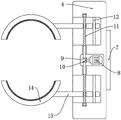
fig. 2 is a partial structural top view of an automatic stringing device for electric lines of an electric power pole according to the present invention;
fig. 3 is a sectional view of a part of the structure of an automatic stringing device for electric lines of an electric power line pole according to the present invention.
In the figure:
the wire rod comprises a wire rod body 1, a wire rod frame 2, a wire fixing frame 3, a clamping box 4, a battery 5, a charging port 6, a control button 7, a first motor 8, a first bevel gear 9, a second bevel gear 10, a threaded rod 11, a sliding rod 12, a fixing rod 13, a clamping block 14, a multi-stage telescopic rod 15, an installation block 16, a conveying roller 17, a second motor 18, a transmission rod 19, an electric telescopic rod 20 and a limiting groove 21.
Detailed Description
In order that the above objects, features and advantages of the present invention can be more clearly understood, a more particular description of the utility model will be rendered by reference to the appended drawings. It should be noted that the embodiments and features of the embodiments of the present application may be combined with each other without conflict.
In the following description, numerous specific details are set forth in order to provide a thorough understanding of the present invention, however, the present invention may be practiced in other ways than those specifically described herein, and therefore the scope of the present invention is not limited by the specific embodiments disclosed below.
The solution of some embodiments of the utility model is described below with reference to fig. 1 and 2.
Example 1
The utility model provides an embodiment, and as shown in fig. 1-3, the automatic stringing device for electric wires of electric power wire poles comprises a wire pole body 1 and a clamping box 4, wherein a plurality of stringing poles 2 are fixedly connected to the wire pole body 1, the stringing poles 2 are fixedly connected to the wire pole body 1 through bolts, each stringing pole 2 is provided with an electric wire fixing frame 3, the electric wire fixing frames 3 are fixedly connected to the stringing poles 2 through welding, the electric wire fixing frames 3 can fix the electric wires, a battery 5 is fixedly connected to the inside of the clamping box 4 and provides electric power for the device, the bottom of the clamping box 4 is provided with a charging port 6 for charging the battery 5, the outer wall of the clamping box 4 is provided with a control button 7, and the provided control button 7 can control the first motor 8, the multi-stage telescopic rod 15 and the second motor 18 to be switched on and off.
A first motor 8 is fixedly connected in the clamping box 4, the tail end of an output shaft of the first motor 8 is fixedly connected with a first bevel gear 9, the first bevel gear 9 is meshed with two second bevel gears 10, both the two second bevel gears 10 are fixedly connected with threaded rods 11, both the threaded rods 11 penetrate through the clamping box 4 and are rotatably connected with the clamping box, the outer walls of both the threaded rods 11 are sleeved with fixing rods 13 in threaded connection with the threaded rods, through holes are formed in the fixing rods 13, the outer walls of the threaded rods 11 and the inner walls of the through holes are respectively provided with matched external threads and internal threads, both sliding rods 12 are fixedly connected on the clamping box 4, both the sliding rods 12 penetrate through the fixing rods 13 and are in sliding connection with the fixing rods, both the fixing rods 13 are in sliding connection with the clamping box 4, both the fixing rods 13 are fixedly connected with clamping blocks 14, the clamping blocks 14 are large in width and can be stably clamped with the wire rod body 1, the looks remote site of two grip blocks 14 all is equipped with the arcwall face, can increase the area of centre gripping, makes the centre gripping more stable, is equipped with the one deck protective sheath on the grip block 14, and the material of protective sheath is rubber, can protect grip block 14, avoids grip block 14 wearing and tearing.
The multi-stage telescopic rod 15 is fixedly connected to the clamping box 4, the conveying mechanism is arranged at the top of the multi-stage telescopic rod 15 and comprises two mounting blocks 16 arranged on the upper side of the multi-stage telescopic rod 15, the top of the multi-stage telescopic rod 15 is fixedly connected with the mounting blocks 16 on the lower side, two electric telescopic rods 20 are fixedly connected between the two mounting blocks 16, the two mounting blocks 16 are rotatably connected with conveying rollers 17, limiting grooves 21 are formed in the conveying rollers 17, the limiting grooves 21 can be attached to electric wires to convey the electric wires and can convey the electric wires with different diameters, the application range is wide, a second motor 18 is fixedly connected to the inside of the mounting block 16 on the upper side, the output end of the second motor 18 is fixedly connected with a transmission rod 19, the transmission rod 19 penetrates through the mounting blocks 16 and is rotatably connected with the mounting blocks, the transmission rod 19 is fixedly connected with the conveying rollers 17 on the upper side, and the electric wires are conveyed, the electric wire is straightened, manual operation is avoided, and manpower is saved.
When the electric wire clamping device is specifically implemented, a worker firstly penetrates an electric wire between the conveying rollers 17, the electric telescopic rod 20 is started to enable the mounting block 16 and the conveying rollers 17 on the upper side to move downwards, the electric wire can be clamped through relative movement of the conveying rollers 17 on the two sides, the electric wires with different diameters and sizes can be clamped, and the electric wire clamping device is wide in application range; then, the two clamping blocks 14 are positioned on the outer wall of the line pole body 1, at the moment, the first motor 8 is started, the output shaft of the first motor 8 drives the first bevel gear 9, the second bevel gear 10 and the threaded rod 11 to rotate, and drives the fixing rods 13 and the clamping blocks 14 on the two sides to move relatively, so that the clamping blocks 14 fix the line pole body 1, the device is fixed on the line pole body 1, the line pole bodies 1 with different diameters and specifications can be fixed, and the practicability is high; start multistage telescopic rod 15, multistage telescopic rod 15 stretches out and to drive installation piece 16, conveying roller 17 and electric wire shift up, until removing the electric wire suitable height, start second motor 18 this moment, the output of second motor 18 drives transfer line 19 and the conveying roller 17 of upside and rotates, and then make the electric wire carry, make the electric wire flare-out, the staff on line rod body 1 after the electric wire flare-out can fix the electric wire installation on electric wire mount 3, the completion is fixed to the electric wire, therefore, the steam generator is simple in operation, therefore, the clothes hanger is strong in practicability.
In the present invention, the terms "first", "second" are used for descriptive purposes only and are not to be construed as indicating or implying relative importance. The terms "connected" and "fixed" are to be construed broadly, e.g., "connected" may be a fixed connection, a removable connection, or an integral connection. The specific meanings of the above terms in the present invention can be understood by those skilled in the art according to specific situations.
In the description of the present invention, it is to be understood that the indicated orientations or positional relationships are based on the orientations or positional relationships shown in the drawings and are only for convenience in describing the present invention and simplifying the description, but do not indicate or imply that the indicated devices or units must have a specific orientation, be constructed and operated in a specific orientation, and thus, should not be construed as limiting the present invention.
In the description of the present specification, the description of the terms "one embodiment," "some embodiments," or the like, means that a particular feature, structure, material, or characteristic described in connection with the embodiment or example is included in at least one embodiment or example of the utility model. In this specification, the schematic representations of the terms used above do not necessarily refer to the same embodiment or example. Furthermore, the particular features, structures, materials, or characteristics described may be combined in any suitable manner in any one or more embodiments or examples.
The above is only a preferred embodiment of the present invention, and is not intended to limit the present invention, and various modifications and changes will occur to those skilled in the art. Any modification, equivalent replacement, or improvement made within the spirit and principle of the present invention should be included in the protection scope of the present invention.
Claims (9)
1. The automatic stringing device for the electric wire of the electric wire pole comprises a wire pole body (1) and a clamping box (4), and is characterized in that a plurality of stringing poles (2) are fixedly connected to the wire pole body (1), an electric wire fixing frame (3) is installed on each stringing pole (2), a battery (5) is fixedly connected to the inside of the clamping box (4), a charging port (6) is arranged at the bottom of the clamping box (4), a control button (7) is installed on the outer wall of the clamping box (4), a first motor (8) is fixedly connected to the inside of the clamping box (4), a first bevel gear (9) is fixedly connected to the tail end of an output shaft of the first motor (8), the first bevel gear (9) is meshed with two second bevel gears (10), the two second bevel gears (10) are both fixedly connected with a threaded rod (11), and the two threaded rods (11) penetrate through the clamping box (4) and are rotatably connected with the clamping box, two the outer wall of threaded rod (11) all overlaps and is equipped with dead lever (13) rather than threaded connection, two slide bar (12), two of fixedly connected with on centre gripping case (4) slide bar (12) run through dead lever (13) respectively and rather than sliding connection, two dead lever (13) all with centre gripping case (4) sliding connection, two equal fixedly connected with grip block (14) in dead lever (13), fixedly connected with multi-stage telescopic rod (15) on centre gripping case (4), the top of multi-stage telescopic rod (15) is equipped with conveying mechanism.
2. The automatic stringing device for the electric power poles and wires according to claim 1, wherein the conveying mechanism comprises two mounting blocks (16) arranged on the upper side of a multi-stage telescopic rod (15), the top of the multi-stage telescopic rod (15) is fixedly connected with the mounting blocks (16) on the lower side, two electric telescopic rods (20) are fixedly connected between the two mounting blocks (16), the two mounting blocks (16) are rotatably connected with conveying rollers (17), a second motor (18) is fixedly connected in the mounting block (16) on the upper side, the output end of the second motor (18) is fixedly connected with a transmission rod (19), the transmission rod (19) penetrates through the mounting blocks (16) and is rotatably connected with the mounting blocks, and the transmission rod (19) is fixedly connected with the conveying rollers (17) on the upper side.
3. The automatic stringing device for electric power line pole wires according to claim 1, characterized in that the fixing rod (13) is provided with a through hole, and the outer wall of the threaded rod (11) and the inner wall of the through hole are respectively provided with a matching external thread and internal thread.
4. The automatic stringing device for electric power poles and wires according to claim 1, characterized in that the stringing pole (2) is fixedly connected to the pole body (1) by means of bolts.
5. The automatic stringing device for electric power line pole wires according to claim 1, characterized in that the wire holder (3) is fixedly connected to the stringing pole (2) by welding.
6. An apparatus for the automated stringing of electric power line pole wires according to claim 1, characterized in that the opposite ends of the two gripping blocks (14) are provided with curved faces.
7. The automatic stringing device for electric lines of electric power poles according to claim 1, characterized in that the gripping block (14) is provided with a protective sheath.
8. The automatic stringing device for power line pole wires according to claim 7, wherein the protective sleeve is made of rubber.
9. The automatic stringing device for electric power poles and wires according to claim 2, characterized in that the feeding rollers (17) are provided with a limiting groove (21).
Priority Applications (1)
| Application Number | Priority Date | Filing Date | Title |
|---|---|---|---|
| CN202122702667.4U CN216904059U (en) | 2021-11-06 | 2021-11-06 | Automatic stringing equipment for electric wires of power line pole |
Applications Claiming Priority (1)
| Application Number | Priority Date | Filing Date | Title |
|---|---|---|---|
| CN202122702667.4U CN216904059U (en) | 2021-11-06 | 2021-11-06 | Automatic stringing equipment for electric wires of power line pole |
Publications (1)
| Publication Number | Publication Date |
|---|---|
| CN216904059U true CN216904059U (en) | 2022-07-05 |
Family
ID=82201694
Family Applications (1)
| Application Number | Title | Priority Date | Filing Date |
|---|---|---|---|
| CN202122702667.4U Active CN216904059U (en) | 2021-11-06 | 2021-11-06 | Automatic stringing equipment for electric wires of power line pole |
Country Status (1)
| Country | Link |
|---|---|
| CN (1) | CN216904059U (en) |
-
2021
- 2021-11-06 CN CN202122702667.4U patent/CN216904059U/en active Active
Similar Documents
| Publication | Publication Date | Title |
|---|---|---|
| CN210640615U (en) | Tightener for electric power engineering cable installation | |
| CN109742678A (en) | Hot line robot equipment on bar | |
| CN216904059U (en) | Automatic stringing equipment for electric wires of power line pole | |
| CN212558638U (en) | Automatic compound coiling mechanism of self-adhesive tape | |
| CN219659302U (en) | Wiring auxiliary device for power engineering construction | |
| CN209516283U (en) | Hot line robot equipment on a kind of bar | |
| CN210106761U (en) | Chemical equipment pipeline supporting device | |
| CN110668266A (en) | Cable handling device for power transmission line | |
| CN210366370U (en) | Cable coiling device for electric power engineering construction | |
| CN217290237U (en) | Circulating cooling device for part production | |
| CN208361609U (en) | Water band rolling-up mechanism with self-locking clamping function | |
| CN217780063U (en) | Automatic grab bucket of building engineering | |
| CN205969467U (en) | Piping lane hand hole mould puller | |
| CN220200949U (en) | Auxiliary paying-off device for cable | |
| CN214652696U (en) | Portable cable wire stretching device | |
| CN211034344U (en) | Prefabricated part production line reinforcing bar net piece winding device | |
| CN215452327U (en) | Cable erection auxiliary tool for state grid power construction | |
| CN115064920B (en) | Multi-strand cable connecting device for power transmission | |
| CN217741131U (en) | Wiring auxiliary device for electric power engineering construction | |
| CN215101149U (en) | Hydraulic hose coiling device | |
| CN215417662U (en) | Power cable convenient to connect | |
| CN217947343U (en) | Novel lifting appliance for lifting beam | |
| CN218242842U (en) | Factory building cable laying frame | |
| CN217756457U (en) | Appurtenance based on automatic formula fishing rod formula lifting device | |
| CN215470601U (en) | High-performance square tube clamping device |
Legal Events
| Date | Code | Title | Description |
|---|---|---|---|
| GR01 | Patent grant | ||
| GR01 | Patent grant |