CN216875447U - Connecting rod formula supporting structure and contain dining-table of this structure - Google Patents
Connecting rod formula supporting structure and contain dining-table of this structure Download PDFInfo
- Publication number
- CN216875447U CN216875447U CN202122546841.0U CN202122546841U CN216875447U CN 216875447 U CN216875447 U CN 216875447U CN 202122546841 U CN202122546841 U CN 202122546841U CN 216875447 U CN216875447 U CN 216875447U
- Authority
- CN
- China
- Prior art keywords
- support
- main
- auxiliary
- platform
- main support
- Prior art date
- Legal status (The legal status is an assumption and is not a legal conclusion. Google has not performed a legal analysis and makes no representation as to the accuracy of the status listed.)
- Active
Links
Images


Abstract
The utility model relates to the technical field of furniture, in particular to a connecting rod type support structure and a dining table comprising the same, wherein the connecting rod type support structure comprises a first main support, the bottom of the first main support is provided with a first main support platform, the top of the first main support is provided with a first main connecting platform and a first auxiliary support, the first auxiliary support is connected with the first main support, the bottom of the first auxiliary support is provided with a first auxiliary supporting platform, and the top of the first auxiliary support is provided with a first auxiliary connecting platform; the second main support is connected with the first auxiliary support, a second main support platform is arranged at the bottom of the second main support, and a second main connecting platform is arranged at the top of the second main support; the second auxiliary support is connected with the first main support and the second main support, a second auxiliary support platform is arranged at the bottom of the second auxiliary support, and a second auxiliary connecting platform is arranged at the top of the second auxiliary support; the utility model is provided with two groups of main brackets and two groups of auxiliary brackets, and the brackets are mutually connected to form a connecting rod type supporting frame structure, so that the integral structure is attractive, the supporting strength is high, the stability is good, and the practicability is strong.
Description
Technical Field
The utility model relates to the technical field of furniture, in particular to a connecting rod type support structure and a dining table comprising the same.
Background
Furniture refers to a large category of appliances and facilities essential for human beings to maintain normal life, engage in production practice and develop social activities. The furniture is continuously developed and innovated following the foot steps of the times, and the door is various in types, different in materials, complete in variety and different in purposes.
At present, the operation development situation of the solid wood furniture industry in China is good, the research center of the research on the data shows that with the continuous expansion of the operation requirement market of the solid wood furniture industry in China, the operation of the solid wood furniture industry in China will meet a new development opportunity, modern Chinese style furniture will become a new focus of consumption, the modern Chinese furniture has both traditional connotation and modern forms, the model is fashionable and elegant, the aesthetic interest of most China is met, and the high-quality material collocation and rich color combination are possessed, so that the elegant and tasteful pursuit of consumers can be met.
The existing furniture has various types, including beds, bedside cabinets, dining tables, tea tables, work tables and the like which are daily used; wherein, current dining-table in use, because the supporting structure design is unreasonable, and whole pleasing to the eye not enough, stability is relatively poor, so can make further improvement to the supporting structure of dining-table.
SUMMERY OF THE UTILITY MODEL
In order to solve the problems, the utility model provides a connecting rod type support structure which is provided with two groups of main supports and two groups of auxiliary supports, wherein the plurality of supports are connected with each other to form the connecting rod type support structure, so that the connecting rod type support structure is attractive in whole, high in support strength, good in stability and strong in practicability, and a dining table comprising the connecting rod type support structure.
The technical scheme adopted by the utility model is as follows: a connecting rod type support structure comprises a first main support, wherein a first main support platform is arranged at the bottom of the first main support, and a first main connecting platform is arranged at the top of the first main support; the first auxiliary support is connected with the first main support, a first auxiliary supporting platform is arranged at the bottom of the first auxiliary support, and a first auxiliary connecting platform is arranged at the top of the first auxiliary support; the second main support is connected with the first auxiliary support, a second main support platform is arranged at the bottom of the second main support, and a second main connecting platform is arranged at the top of the second main support; the second auxiliary support is connected with the first main support and the second main support, the bottom of the second auxiliary support is provided with a second auxiliary support platform, and the top of the second auxiliary support is provided with a second auxiliary connection platform.
The further improvement of the above scheme is that the first main support is in a semi-arch shape, the first main support platform is connected with a first main gasket, and the first main connecting platform is connected with a first cross beam.
The further improvement of the scheme is that the first auxiliary support is in a semi-arc shape, the first auxiliary supporting platform is connected with a first auxiliary gasket, and the first auxiliary connecting platform is connected with a second cross beam.
The further improvement to above-mentioned scheme does, the second auxiliary support is the setting of semi-bow shape, the vice supporting platform of second is connected with the vice gasket of second, the vice connection platform of second is connected with the second crossbeam.
The further improvement of the above scheme is that the second main support is in a semi-arch shape, the second main support platform is connected with a second main gasket, and the second main connecting platform is connected with a third cross beam.
The further improvement of the scheme is that the first beam, the second beam and the third beam are positioned on the same horizontal plane.
The further improvement of the scheme is that the first main gasket, the first auxiliary gasket, the second auxiliary gasket and the second main gasket are positioned on the same horizontal plane.
The further improvement of the above scheme is that the first main support is connected with the first auxiliary support through a screw, the first auxiliary support is connected with the second main support through a screw, and the second auxiliary support is connected with the first main support and the second main support through a screw.
A dining table, which comprises the connecting rod type bracket structure.
The further improvement to above-mentioned scheme does, including the table frame, the table frame is connected with first main connection platform, the vice connection platform of first vice connection platform second main connection platform and the vice connection platform of second, table frame surface mounting has the marble slab.
The beneficial effects of the utility model are:
compared with the traditional bracket structure of the clamp dining table, the bracket structure of the clamp dining table is provided with two groups of main brackets and two groups of auxiliary brackets, and the brackets are connected with each other to form a connecting rod type supporting frame structure, so that the overall structure is attractive, the supporting strength is high, the stability is good, and the practicability is high. Specifically, a first main support is arranged, a first main support platform is arranged at the bottom of the first main support, and a first main connecting platform is arranged at the top of the first main support; the first auxiliary support is connected with the first main support, a first auxiliary supporting platform is arranged at the bottom of the first auxiliary support, and a first auxiliary connecting platform is arranged at the top of the first auxiliary support; the second main support is connected with the first auxiliary support, a second main support platform is arranged at the bottom of the second main support, and a second main connecting platform is arranged at the top of the second main support; the second auxiliary support is connected with the first main support and the second main support, the bottom of the second auxiliary support is provided with a second auxiliary support platform, and the top of the second auxiliary support is provided with a second auxiliary connection platform. The bottom and the top of the main support and the secondary support are respectively provided with a supporting platform and a connecting platform which are respectively used for supporting and connecting the action structures, the whole structure is stable and reliable, and the supporting effect is good.
Drawings
FIG. 1 is a front view of a dining table according to the present invention;
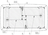
FIG. 2 is a schematic top view of the dining table of FIG. 1;
fig. 3 is a side view of the dining table of fig. 1.
Description of reference numerals: the main support comprises a first main support 1, a first main support platform 11, a first main gasket 111, a first main connecting platform 12, a first cross beam 121, a first auxiliary support 2, a first auxiliary support platform 21, a first auxiliary gasket 211, a second cross beam 212, a first auxiliary connecting platform 22, a second main support 3, a second main support platform 31, a second main gasket 311, a second main connecting platform 32, a third cross beam 321, a second auxiliary support 4, a second auxiliary support platform 41, a second auxiliary gasket 411, a second auxiliary connecting platform 42, a table frame 5 and a marble plate 51.
Detailed Description
To facilitate an understanding of the utility model, the utility model will now be described more fully with reference to the accompanying drawings. Preferred embodiments of the present invention are shown in the drawings. This invention may, however, be embodied in many different forms and should not be construed as limited to the embodiments set forth herein. Rather, these embodiments are provided so that this disclosure will be thorough and complete.
It will be understood that when an element is referred to as being "secured to" another element, it can be directly on the other element or intervening elements may also be present. When an element is referred to as being "connected" to another element, it can be directly connected to the other element or intervening elements may also be present.
Unless defined otherwise, all technical and scientific terms used herein have the same meaning as commonly understood by one of ordinary skill in the art to which this invention belongs. The terminology used in the description of the utility model herein is for the purpose of describing particular embodiments only and is not intended to be limiting of the utility model.
As shown in fig. 1 to 3, a link type support structure includes a first main support 1, a first main support platform 11 is provided at the bottom of the first main support 1, and a first main connecting platform 12 is provided at the top; the first secondary support 2 is connected with the first main support 1, a first secondary supporting platform 21 is arranged at the bottom of the first secondary support 2, and a first secondary connecting platform 22 is arranged at the top of the first secondary support 2; the second main support 3 is connected with the first auxiliary support 2, a second main support platform 31 is arranged at the bottom of the second main support 3, and a second main connecting platform 32 is arranged at the top of the second main support 3; and the second auxiliary support 4 is connected with the first main support 1 and the second main support 3, the bottom of the second auxiliary support 4 is provided with a second auxiliary support platform 41, and the top of the second auxiliary support 4 is provided with a second auxiliary connecting platform 42.
The first main support 1 is arranged in a semi-arc shape, the first main support platform 11 is connected with a first main gasket 111, the first main connecting platform 12 is connected with a first cross beam 121, and the further improvement is that the first auxiliary support 2 is arranged in a semi-arc shape, the first auxiliary support platform 21 is connected with a first auxiliary gasket 211, and the first auxiliary connecting platform 22 is connected with a second cross beam 212; the second auxiliary support 4 is arranged in a semi-arc shape, the second auxiliary support platform 41 is connected with a second auxiliary gasket 411, and the second auxiliary connecting platform 42 is connected with the second cross beam 212; the second main support 3 is half bow-shaped setting, second main supporting platform 31 is connected with second main gasket 311, second main connecting platform 32 is connected with third crossbeam 321, adopts half bow-shaped structure's support, and stable in structure is reliable, and is whole pleasing to the eye, sets up the gasket simultaneously and is used for the bottom to place the pad, sets up the crossbeam and is used for overall structure to connect, and the structure is reliable.
In this embodiment, the first cross beam 121, the second cross beam 212 and the third cross beam 321 are located at the same horizontal plane, and the first main gasket 111, the first auxiliary gasket 211, the second auxiliary gasket 411 and the second main gasket 311 are located at the same horizontal plane, so as to ensure that the dining table has a flat structure and stable connection in use.
First main support 1 passes through the screw and is connected with first secondary support 2, first secondary support 2 passes through the screw and is connected with second main support 3, second secondary support 4 leads to the screw and is connected with first main support 1 and second main support 3, and it is fixed with a plurality of support interconnect through the screw, and the equipment is convenient, stable in structure.
The dining table, including table frame 5, table frame 5 is connected with first main connecting platform 12, first vice connecting platform 22 second main connecting platform 32 and the vice connecting platform 42 of second, 5 surface mounting on table frame have marble board 51, through table frame 5 and connecting platform structural connection, stable in structure is reliable, simple to operate to set up marble board 51 and form the desktop, it is whole more pleasing to the eye, more have the feel.
The utility model is provided with two groups of main brackets and two groups of auxiliary brackets, and the brackets are mutually connected to form a connecting rod type supporting frame structure, so that the integral structure is attractive, the supporting strength is high, the stability is good, and the practicability is strong. Specifically, a first main support 1 is provided, a first main support platform 11 is provided at the bottom of the first main support 1, and a first main connecting platform 12 is provided at the top; the first secondary support 2 is connected with the first main support 1, a first secondary supporting platform 21 is arranged at the bottom of the first secondary support 2, and a first secondary connecting platform 22 is arranged at the top of the first secondary support 2; the second main support 3 is connected with the first auxiliary support 2, a second main support platform 31 is arranged at the bottom of the second main support 3, and a second main connecting platform 32 is arranged at the top of the second main support 3; and the second auxiliary support 4 is connected with the first main support 1 and the second main support 3, the bottom of the second auxiliary support 4 is provided with a second auxiliary support platform 41, and the top of the second auxiliary support 4 is provided with a second auxiliary connecting platform 42. The bottom and the top of the main support and the secondary support are respectively provided with a supporting platform and a connecting platform which are respectively used for supporting and connecting the action structures, the whole structure is stable and reliable, and the supporting effect is good.
The above-mentioned embodiments only express several embodiments of the present invention, and the description thereof is more specific and detailed, but not construed as limiting the scope of the present invention. It should be noted that various changes and modifications can be made by those skilled in the art without departing from the spirit of the utility model, and these changes and modifications are all within the scope of the utility model. Therefore, the protection scope of the present patent shall be subject to the appended claims.
Claims (5)
1. The utility model provides a connecting rod formula bearing structure which characterized in that: comprises that
The bottom of the first main support is provided with a first main supporting platform, and the top of the first main support is provided with a first main connecting platform;
the first auxiliary support is connected with the first main support, a first auxiliary supporting platform is arranged at the bottom of the first auxiliary support, and a first auxiliary connecting platform is arranged at the top of the first auxiliary support;
the second main support is connected with the first auxiliary support, a second main support platform is arranged at the bottom of the second main support, and a second main connecting platform is arranged at the top of the second main support;
the second auxiliary support is connected with the first main support and the second main support, a second auxiliary support platform is arranged at the bottom of the second auxiliary support, and a second auxiliary connecting platform is arranged at the top of the second auxiliary support;
the first main support is arranged in a semi-arc shape, the first main support platform is connected with a first main gasket, and the first main connecting platform is connected with a first cross beam;
the first auxiliary support is arranged in a semi-arc shape, the first auxiliary support platform is connected with a first auxiliary gasket, and the first auxiliary connecting platform is connected with a second cross beam;
the second auxiliary support is arranged in a semi-arc shape, the second auxiliary support platform is connected with a second auxiliary gasket, and the second auxiliary connecting platform is connected with the second cross beam;
the second main support is arranged in a semi-arc shape, the second main support platform is connected with a second main gasket, and the second main connecting platform is connected with a third cross beam;
the first cross beam, the second cross beam and the third cross beam are positioned on the same horizontal plane.
2. The link bracket structure according to claim 1, wherein: the first main gasket, the first auxiliary gasket, the second auxiliary gasket and the second main gasket are positioned on the same horizontal plane.
3. The link bracket structure according to claim 2, wherein: the first main support is connected with the first auxiliary support through a screw, the first auxiliary support is connected with the second main support through a screw, and the second auxiliary support is connected with the first main support and the second main support through screws.
4. A dining table, characterized in that: comprising a link-type support structure according to any one of claims 1 to 3.
5. The dining table of claim 4, wherein: including the table frame, the table frame is connected with first main connection platform, first vice connection platform second main connection platform and the vice connection platform of second, table frame surface mounting has the marble slab.
Priority Applications (1)
| Application Number | Priority Date | Filing Date | Title |
|---|---|---|---|
| CN202122546841.0U CN216875447U (en) | 2021-10-21 | 2021-10-21 | Connecting rod formula supporting structure and contain dining-table of this structure |
Applications Claiming Priority (1)
| Application Number | Priority Date | Filing Date | Title |
|---|---|---|---|
| CN202122546841.0U CN216875447U (en) | 2021-10-21 | 2021-10-21 | Connecting rod formula supporting structure and contain dining-table of this structure |
Publications (1)
| Publication Number | Publication Date |
|---|---|
| CN216875447U true CN216875447U (en) | 2022-07-05 |
Family
ID=82195663
Family Applications (1)
| Application Number | Title | Priority Date | Filing Date |
|---|---|---|---|
| CN202122546841.0U Active CN216875447U (en) | 2021-10-21 | 2021-10-21 | Connecting rod formula supporting structure and contain dining-table of this structure |
Country Status (1)
| Country | Link |
|---|---|
| CN (1) | CN216875447U (en) |
-
2021
- 2021-10-21 CN CN202122546841.0U patent/CN216875447U/en active Active
Similar Documents
| Publication | Publication Date | Title |
|---|---|---|
| CN202603992U (en) | Extensible table | |
| CN216875447U (en) | Connecting rod formula supporting structure and contain dining-table of this structure | |
| CN205831527U (en) | A kind of Multifunctional assembled furnature | |
| CN216569071U (en) | Combined desk and chair with adjustable use space for teaching | |
| CN201119573Y (en) | Dining table | |
| CN201591335U (en) | Long chair capable of changing into table | |
| CN201577755U (en) | Diagonal high-low regulation type ascending and descending table | |
| CN216534623U (en) | Bedstead and bed based on metal support structure | |
| CN216534518U (en) | Object placing bracket structure and office table comprising same | |
| CN207118728U (en) | Built-up table subframe | |
| CN209346277U (en) | A kind of expansible desk | |
| CN203137725U (en) | Adjustable infant dining table and chair | |
| CN210095128U (en) | Simple table and chair combined structure | |
| CN216534507U (en) | Multi-plate-frame supporting structure and bedside table comprising same | |
| CN205143902U (en) | Multifunctional table | |
| CN201045943Y (en) | Improved structure of furnishings | |
| CN213909015U (en) | Stool and dining table applying same | |
| CN213216142U (en) | Novel multifunctional turnover chair | |
| CN208318783U (en) | A kind of simple adjustable armrest of structure | |
| CN210581703U (en) | Space-saving assembled table and chair | |
| CN217408289U (en) | Multifunctional chair capable of being changed into table and chair | |
| CN108685331A (en) | Novel and multifunctional tea table | |
| CN211933109U (en) | Multifunctional dining table | |
| CN216627775U (en) | Table with folding function | |
| CN208676594U (en) | A kind of School desk for child |
Legal Events
| Date | Code | Title | Description |
|---|---|---|---|
| GR01 | Patent grant | ||
| GR01 | Patent grant |