CN216872665U - Outdoor corrosion-resistant box-type substation - Google Patents
Outdoor corrosion-resistant box-type substation Download PDFInfo
- Publication number
- CN216872665U CN216872665U CN202122702474.9U CN202122702474U CN216872665U CN 216872665 U CN216872665 U CN 216872665U CN 202122702474 U CN202122702474 U CN 202122702474U CN 216872665 U CN216872665 U CN 216872665U
- Authority
- CN
- China
- Prior art keywords
- fixed
- box
- wall
- plate
- type
- Prior art date
- Legal status (The legal status is an assumption and is not a legal conclusion. Google has not performed a legal analysis and makes no representation as to the accuracy of the status listed.)
- Active
Links
Images


Landscapes
- Testing Resistance To Weather, Investigating Materials By Mechanical Methods (AREA)
Abstract
The utility model belongs to the technical field of box-type substations, and particularly relates to an outdoor corrosion-resistant box-type substation. According to the utility model, the cold air blown out by the air cooler body is conveyed to the spray head, and then the spray head is driven by the movable plate to move up and down for heat dissipation, so that the heat dissipation of the electrical components in the box body is more uniform, and the heat dissipation speed of the electrical components can be increased, thereby avoiding the phenomenon that the electrical components in the box body are damaged due to overhigh temperature in the box body.
Description
Technical Field
The utility model relates to the technical field of box-type substations, in particular to an outdoor corrosion-resistant box-type substation.
Background
The box-type transformer substation, also called a prefabricated transformer substation or a prefabricated transformer substation, is a high-voltage switch device, a distribution transformer and a low-voltage distribution device, is factory prefabricated indoor and outdoor compact distribution equipment which are arranged into a whole according to a certain wiring scheme, namely, the functions of transformer voltage reduction, low-voltage distribution and the like are organically combined together and installed in a moistureproof, anticorrosive and dustproof steel structure box body, and the box-type transformer substation is particularly suitable for city network construction and transformation and is a brand-new transformer substation which is built up after civil construction.
The inside heat dispersion of present transformer substation box is relatively poor, and its inside high temperature of during operation can lead to the inside electrical components of box to take place to damage, and box vent filter screen generally all fixes through the bolt simultaneously, and when the filter screen takes place to damage and need change, the dismouting is inconvenient, consequently, we have proposed an outdoor corrosion-resistant box-type substation and have solved above-mentioned problem.
SUMMERY OF THE UTILITY MODEL
Technical problem to be solved
Aiming at the defects of the prior art, the utility model provides an outdoor corrosion-resistant box-type substation, which solves the problems in the background technology.
(II) technical scheme
The utility model specifically adopts the following technical scheme for realizing the purpose:
an outdoor corrosion-resistant box-type substation comprises a box body, wherein sliding doors are hinged to the front of the box body at equal intervals, handles are fixed to one side wall of each sliding door, two lead screws are rotatably connected to the inside of the box body through bearings, rotating wheels are fixed to the surfaces of the lead screws, the two rotating wheels are connected through belt transmission, a motor is fixed to the inside of the box body, the output end of the motor is fixedly connected with the bottom end of one of the lead screws, a moving plate is connected to the surfaces of the two lead screws through threads, a straight pipe is fixed to one side wall of the moving plate, nozzles are fixedly communicated with the surfaces of the straight pipes at equal intervals, an air cooler body is fixed to the inside of the box body, a hose is fixedly communicated with the air outlet end of the air cooler body, the other end of the hose is fixedly communicated with one end of the straight pipe, ventilation openings are formed in the two side walls of the box body, and surrounding plates are fixed to the inner walls of the ventilation openings, one side of bounding wall all is provided with the filter screen board, the top and the bottom of filtering the screen board all are fixed with L type inserted block, L type inserted block all pegs graft in the inside of bounding wall, is located the top two jacks have been seted up at the top of L type inserted block, the top of bounding wall all is provided with the fixed subassembly that is used for the block jack.
Further, fixed subassembly is including fixing the U template at the bounding wall top, the top sliding connection of U template has two inserted bars, the bottom of inserted bar all runs through the top of bounding wall and pegs graft in the inside of jack, two the fixed surface of inserted bar has the limiting plate, the surface of inserted bar all overlaps and is equipped with the spring, two the both ends of spring respectively with the top inner wall of U template and the top fixed connection of limiting plate, the top of U template is provided with L type arm-tie, the top fixed connection of the top of U template and limiting plate is run through to the bottom of L type arm-tie.
Furthermore, two sliding rails are symmetrically fixed on the inner wall of the box body, and two sliding blocks matched with the sliding rails are symmetrically fixed on one side wall of the moving plate.
Furthermore, two vertical plates are symmetrically fixed to the top of the box body, and baffles are fixed to the tops of the vertical plates.
Further, the outer wall of the ventilation opening is fixed with protection plates at equal intervals.
Furthermore, two slots matched with the L-shaped inserting blocks are formed in one side wall of each enclosing plate.
(III) advantageous effects
Compared with the prior art, the utility model provides an outdoor corrosion-resistant box-type substation, which has the following beneficial effects:
according to the utility model, by arranging the box body, the lead screw, the movable plate, the air cooler body, the spray head, the hose, the surrounding plate, the filter screen plate, the L-shaped insert block and the fixed assembly, cold air blown out by the air cooler body is conveyed to the spray head, and then the movable plate drives the spray head to move up and down to dissipate heat, so that electrical components in the box body can dissipate heat more uniformly, and the heat dissipation speed can be increased, thereby avoiding the phenomenon that the electrical components in the box body are damaged due to overhigh temperature in the box body.
Drawings
FIG. 1 is a schematic view of the overall structure of the present invention;
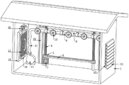
FIG. 2 is a schematic view of the internal structure of the case according to the present invention;
FIG. 3 is a schematic structural view of a shroud according to the present invention;
FIG. 4 is a schematic view of a filter screen structure according to the present invention;
FIG. 5 is a schematic diagram of the moving plate structure of the present invention.
In the figure: 1. a box body; 2. sliding the door; 3. a handle; 4. a screw rod; 5. a rotating wheel; 6. a belt; 7. a motor; 8. moving the plate; 9. a straight pipe; 10. a spray head; 11. an air cooler body; 12. a hose; 13. a vent; 14. enclosing plates; 15. a filter screen plate; 16. an L-shaped insert block; 17. a jack; 18. a fixing assembly; 1801. a U-shaped plate; 1802. inserting a rod; 1803. a limiting plate; 1804. a spring; 1805. an L-shaped pulling plate; 19. a slide rail; 20. a slider; 21. a vertical plate; 22. a baffle plate; 23. a protection plate; 24. and (4) a slot.
Detailed Description
The technical solutions in the embodiments of the present invention will be clearly and completely described below with reference to the drawings in the embodiments of the present invention, and it is obvious that the described embodiments are only a part of the embodiments of the present invention, and not all of the embodiments. All other embodiments, which can be derived by a person skilled in the art from the embodiments given herein without making any creative effort, shall fall within the protection scope of the present invention.
Examples
As shown in fig. 1, 2, 3, 4 and 5, an outdoor corrosion-resistant box-type substation according to an embodiment of the present invention includes a box 1, sliding doors 2 are hinged to the front of the box 1 at equal intervals, a handle 3 is fixed to one side wall of each sliding door 2, two lead screws 4 are rotatably connected to the inside of the box 1 through bearings, rotating wheels 5 are fixed to the surfaces of the lead screws 4, the two rotating wheels 5 are in transmission connection through belts 6, a motor 7 is fixed to the inside of the box 1, an output end of the motor 7 is fixedly connected to a bottom end of one of the lead screws 4, a moving plate 8 is in threaded connection with the surfaces of the two lead screws 4, a straight pipe 9 is fixed to one side wall of the moving plate 8, nozzles 10 are fixed to the surfaces of the straight pipes 9 at equal intervals, an air cooler body 11 is fixed to the inside of the box 1, a hose 12 is fixed to an air outlet end of the air cooler body 11, and the other end of the hose 12 is fixedly connected to one end of the straight pipe 9, the two side walls of the box body 1 are respectively provided with a vent 13, the inner walls of the vents 13 are respectively fixed with a surrounding plate 14, one side of the surrounding plate 14 is respectively provided with a filter screen plate 15, the top and the bottom of the filter screen plate 15 are respectively fixed with an L-shaped insert block 16, the L-shaped insert blocks 16 are respectively inserted into the surrounding plates 14, the top of the top L-shaped insert block 16 is provided with two jacks 17, the top of the surrounding plate 14 is respectively provided with a fixing component 18 for clamping the jacks 17, when in use, the air cooler body 11 is started, the air cooler body 11 transmits blown cold air to the inside of a straight pipe 9 through a hose 12, and finally transmits the cold air to a spray head 10 through the straight pipe 9, then the motor 7 is started, the motor 7 drives one of the screw rods 4 to rotate, the rotating wheels 5 fixed on the surfaces of the two screw rods 4 are transmitted through a belt 6, so that the two screw rods 4 can synchronously rotate, the screw rods 4 rotate to drive a moving plate 8 to move up and down, the moving plate 8 moves up and down to drive the spray head 10 to move, so that heat dissipation can be rapidly performed on the interior of the box body 1.
As shown in fig. 2 and 3, in some embodiments, the fixing assembly 18 includes a U-shaped plate 1801 fixed on the top of the enclosing plate 14, two insertion rods 1802 are slidably connected to the top of the U-shaped plate 1801, the bottom ends of the insertion rods 1802 penetrate through the top of the enclosing plate 14 and are inserted into the insertion holes 17, a limiting plate 1803 is fixed to the surface of the two insertion rods 1802, a spring 1804 is sleeved on the surface of the insertion rod 1802, two ends of the two springs 1804 are respectively fixedly connected to the inner wall of the top of the U-shaped plate 1801 and the top of the limiting plate 1803, an L-shaped pulling plate 1805 is arranged above the U-shaped plate 1801, the bottom of the L-shaped pulling plate 1805 penetrates through the top of the U-shaped plate 1801 and is fixedly connected to the top of the limiting plate 1803, in use, through pulling L type arm-tie 1805, thereby L type arm-tie 1805 drives limiting plate 1803 and removes and drives inserted bar 1802 and remove, and the inside roll-off of jack 17 has been followed to the bottom of inserted bar 1802, has removed the restriction to filtering otter board 15, can pull down filtering otter board 15 this moment.
As shown in fig. 2 and 5, in some embodiments, two sliding rails 19 are symmetrically fixed on the inner wall of the box 1, and two sliding blocks 20 matched with the sliding rails 19 are symmetrically fixed on a side wall of the moving plate 8, so that when the screw 4 rotates to drive the moving plate 8 to move up and down, the moving plate 8 can be more stable when moving.
In some embodiments, as shown in fig. 2, two vertical plates 21 are symmetrically fixed on the top of the box body 1, and a baffle 22 is fixed on the top of the two vertical plates 21, so as to protect the top of the box body 1, thereby preventing the top of the box body from being damaged by falling of foreign matters.
As shown in fig. 1 and 2, in some embodiments, the outer wall of the ventilation opening 13 is fixed with the protection plate 23 at equal intervals, so as to be able to shield rain, and at the same time, to reduce the blocking of the filter screen 15 by flocculent foreign matters, thereby affecting the ventilation and heat dissipation inside the box body 1.
As shown in fig. 3, in some embodiments, two slots 24 adapted to the L-shaped insertion block 16 are formed in a side wall of each of the two enclosing plates 14, so that the L-shaped insertion block 16 can be inserted into the enclosing plate 14, so as to fix the enclosing plate.
Finally, it should be noted that: although the present invention has been described in detail with reference to the foregoing embodiments, it will be apparent to those skilled in the art that changes may be made in the embodiments and/or equivalents thereof without departing from the spirit and scope of the utility model. Any modification, equivalent replacement, or improvement made within the spirit and principle of the present invention should be included in the protection scope of the present invention.
Claims (6)
1. The utility model provides an outdoor corrosion-resistant box-type substation, includes box (1), its characterized in that: the air cooler is characterized in that a sliding door (2) is hinged to the front of the box body (1) at an equal distance, a handle (3) is fixed to one side wall of the sliding door (2), the inside of the box body (1) is rotatably connected with two lead screws (4) through bearings, the surfaces of the lead screws (4) are respectively fixed with a rotating wheel (5) and two rotating wheels (5) which are in transmission connection through a belt (6), a motor (7) is fixed to the inside of the box body (1), the output end of the motor (7) is fixedly connected with the bottom end of one lead screw (4), the surface threads of the two lead screws (4) are connected with a movable plate (8), a straight pipe (9) is fixed to one side wall of the movable plate (8), a spray nozzle (10) is fixed to the surface equal distance of the straight pipe (9), a fan body (11) is fixed to the inside of the box body (1), a hose (12) is fixed to the air outlet end of the fan body (11), the other end of hose (12) is fixed with the one end intercommunication of straight tube (9), vent (13) have all been seted up to the both sides wall of box (1), the inner wall of vent (13) all is fixed with bounding wall (14), one side of bounding wall (14) all is provided with filter plate (15), the top and the bottom of filter plate (15) all are fixed with L type inserted block (16), L type inserted block (16) all peg graft in the inside of bounding wall (14), are located the top two jack (17) have been seted up at the top of L type inserted block (16), the top of bounding wall (14) all is provided with fixed subassembly (18) that are used for block jack (17).
2. An outdoor corrosion-resistant box-type substation according to claim 1, characterized in that: fixed subassembly (18) are including fixing U template (1801) at bounding wall (14) top, the top sliding connection of U template (1801) has two inserted bars (1802), the bottom of inserted bar (1802) all runs through the inside of pegging graft in jack (17) in the top of bounding wall (14), two the fixed surface of inserted bar (1802) has limiting plate (1803), the surface of inserted bar (1802) all overlaps and is equipped with spring (1804), two the both ends of spring (1804) respectively with the top inner wall of U template (1801) and the top fixed connection of limiting plate (1803), the top of U template (1801) is provided with L type and draws board (1805), the top fixed connection of the top of U template (1801) and limiting plate (1803) is run through to the bottom of L type and draws board (1805).
3. An outdoor corrosion-resistant box-type substation according to claim 1, characterized in that: the inner wall of the box body (1) is symmetrically fixed with two sliding rails (19), and one side wall of the moving plate (8) is symmetrically fixed with two sliding blocks (20) matched with the sliding rails (19).
4. An outdoor corrosion-resistant box-type substation according to claim 1, characterized in that: the top symmetry of box (1) is fixed with two riser (21), two the top of riser (21) is fixed with baffle (22).
5. An outdoor corrosion-resistant box-type substation according to claim 1, characterized in that: the outer wall of the ventilation opening (13) is fixed with protection plates (23) at equal intervals.
6. An outdoor corrosion-resistant box-type substation according to claim 1, characterized in that: two slots (24) matched with the L-shaped inserting blocks (16) are formed in one side wall of each enclosing plate (14).
Priority Applications (1)
| Application Number | Priority Date | Filing Date | Title |
|---|---|---|---|
| CN202122702474.9U CN216872665U (en) | 2021-11-06 | 2021-11-06 | Outdoor corrosion-resistant box-type substation |
Applications Claiming Priority (1)
| Application Number | Priority Date | Filing Date | Title |
|---|---|---|---|
| CN202122702474.9U CN216872665U (en) | 2021-11-06 | 2021-11-06 | Outdoor corrosion-resistant box-type substation |
Publications (1)
| Publication Number | Publication Date |
|---|---|
| CN216872665U true CN216872665U (en) | 2022-07-01 |
Family
ID=82126898
Family Applications (1)
| Application Number | Title | Priority Date | Filing Date |
|---|---|---|---|
| CN202122702474.9U Active CN216872665U (en) | 2021-11-06 | 2021-11-06 | Outdoor corrosion-resistant box-type substation |
Country Status (1)
| Country | Link |
|---|---|
| CN (1) | CN216872665U (en) |
-
2021
- 2021-11-06 CN CN202122702474.9U patent/CN216872665U/en active Active
Similar Documents
| Publication | Publication Date | Title |
|---|---|---|
| CN201064064Y (en) | Dustproof electric cabinet | |
| CN112886443B (en) | Outdoor intelligent high-low voltage switch cabinet with automatic protection function | |
| CN110162150A (en) | A kind of computer host box with high-effective dust-removing function | |
| CN211556593U (en) | Armored movable alternating current metal enclosed switchgear | |
| CN216872665U (en) | Outdoor corrosion-resistant box-type substation | |
| CN115425530A (en) | Indoor heat dissipation dust collector of high voltage substation | |
| CN116979462A (en) | Intensive bus duct | |
| CN208985818U (en) | A kind of box type transformer easy to remove | |
| CN216251824U (en) | Ring main unit convenient to heat dissipation exhaust | |
| CN209913265U (en) | Low-voltage distributed photovoltaic grid-connected cabinet | |
| CN220673116U (en) | Dustproof box-type substation of cooling function | |
| CN209993980U (en) | Movable box-type substation | |
| CN220874113U (en) | Assembled energy storage power station | |
| CN219892786U (en) | Constant-temperature high-low voltage switch cabinet | |
| CN220421203U (en) | Block terminal convenient to installation electric device | |
| CN219325738U (en) | Protective charging cabinet | |
| CN219659175U (en) | High-voltage reactive compensation cabinet | |
| CN220628659U (en) | High-voltage switch cabinet | |
| CN215452115U (en) | Middle-mounted switch cabinet | |
| CN220754056U (en) | Box-type substation convenient to installation wiring | |
| CN211507288U (en) | Resin insulation dry-type transformer convenient to installation and maintenance | |
| CN220896082U (en) | Composite weak current box | |
| CN216413636U (en) | Outdoor waterproof type electric-energy metering box with double-door structure | |
| CN218449120U (en) | Ventilation structure and electric power cabinet thereof | |
| CN216016040U (en) | Movable high-voltage switch cabinet |
Legal Events
| Date | Code | Title | Description |
|---|---|---|---|
| GR01 | Patent grant | ||
| GR01 | Patent grant |