CN216859849U - High-speed slitting device for paper production and processing - Google Patents
High-speed slitting device for paper production and processing Download PDFInfo
- Publication number
- CN216859849U CN216859849U CN202220606002.5U CN202220606002U CN216859849U CN 216859849 U CN216859849 U CN 216859849U CN 202220606002 U CN202220606002 U CN 202220606002U CN 216859849 U CN216859849 U CN 216859849U
- Authority
- CN
- China
- Prior art keywords
- fixedly connected
- plate
- groove
- blade
- moving
- Prior art date
- Legal status (The legal status is an assumption and is not a legal conclusion. Google has not performed a legal analysis and makes no representation as to the accuracy of the status listed.)
- Expired - Fee Related
Links
Images


Landscapes
- Nonmetal Cutting Devices (AREA)
Abstract
本实用新型公开了一种纸张生产加工用高速分切装置,包括底板,所述底板的上端固定连接有两个对称设置的限位杆,两个所述限位杆的上端共同固定连接有顶板,两个所述限位杆上均滑动套接有套管,两个所述套管上共同固定套接有移动板,所述顶板的下端设置有用于对移动板进行升降的升降机构,所述移动板的下端固定连接有固定板,所述固定板的下端开设有凹槽,所述凹槽的内部滑动连接有刀片,所述刀片的上端固定连接有竖板。本实用新型结构合理,通过设置移动机构,当刀片与纸张接触时,刀片在纸张上往复移动,实现对纸张进行更加有效的切割,有效的防止纸张未被完全切断的情况发生,提高装置的实用性。
The utility model discloses a high-speed slitting device for paper production and processing, comprising a bottom plate, the upper end of the bottom plate is fixedly connected with two symmetrically arranged limit rods, and the upper ends of the two limit rods are fixedly connected with a top plate together , a sleeve is slidably sleeved on the two limit rods, a moving plate is fixedly sleeved on the two sleeves together, and the lower end of the top plate is provided with a lifting mechanism for lifting and lowering the moving plate. A fixed plate is fixedly connected to the lower end of the moving plate, a groove is formed at the lower end of the fixed plate, a blade is slidably connected inside the groove, and a vertical plate is fixedly connected to the upper end of the blade. The utility model has a reasonable structure. By arranging a moving mechanism, when the blade is in contact with the paper, the blade moves back and forth on the paper, thereby realizing more effective cutting of the paper, effectively preventing the occurrence of the incomplete cutting of the paper, and improving the practicality of the device. sex.
Description
技术领域technical field
本实用新型涉及纸张加工技术领域,尤其涉及一种纸张生产加工用高速分切装置。The utility model relates to the technical field of paper processing, in particular to a high-speed slitting device for paper production and processing.
背景技术Background technique
纸张切割是纸张加工过程中必不可少的步骤之一,纸张在生产后,需要将其切割呈大小相同的合适尺寸,以便于后期使用。Paper cutting is one of the indispensable steps in the paper processing process. After the paper is produced, it needs to be cut into the same size and suitable size for later use.
为提高工作效率,减少劳动力的使用,大多数造纸厂都采用机器对纸张进行切割,现有技术中,传统的切割装置大多采用冲压式切割,即利用刀片的上下移动完成切割,但是这样的方式存在一定的弊端,如其冲切时,很容易造成纸张之间没有被完全切开,导致纸张之间连接在一起,不仅影响切割效果,而且影响产品质量。In order to improve work efficiency and reduce the use of labor, most paper mills use machines to cut paper. In the prior art, most of the traditional cutting devices use punching cutting, that is, the cutting is completed by using the up and down movement of the blade, but this method There are certain drawbacks, such as punching, it is easy to cause the paper to be not completely cut, resulting in the connection between the paper, which not only affects the cutting effect, but also affects the quality of the product.
实用新型内容Utility model content
本实用新型的目的是为了解决现有技术中存在的缺点,而提出的一种纸张生产加工用高速分切装置。The purpose of the utility model is to propose a high-speed slitting device for paper production and processing in order to solve the shortcomings existing in the prior art.
为了实现上述目的,本实用新型采用了如下技术方案:In order to achieve the above-mentioned purpose, the utility model adopts the following technical solutions:
一种纸张生产加工用高速分切装置,包括底板,所述底板的上端固定连接有两个对称设置的限位杆,两个所述限位杆的上端共同固定连接有顶板,两个所述限位杆上均滑动套接有套管,两个所述套管上共同固定套接有移动板,所述顶板的下端设置有用于对移动板进行升降的升降机构,所述移动板的下端固定连接有固定板,所述固定板的下端开设有凹槽,所述凹槽的内部滑动连接有刀片,所述刀片的上端固定连接有竖板,所述竖板的内部开设有通槽,所述凹槽内设置有用于对刀片进行移动的移动机构,所述移动机构包括转动连接在凹槽内壁上的转动杆,所述转动杆的端部固定套接有不完全齿轮,所述通槽的上下内壁上均固定连接有多个与不完全齿轮相配合的第一齿,所述凹槽内还设置有用于对刀片进行限位的限位机构。A high-speed slitting device for paper production and processing, comprising a bottom plate, the upper end of the bottom plate is fixedly connected with two symmetrically arranged limit rods, the upper ends of the two limit rods are fixedly connected with a top plate, and the two The limit rods are both slidably sleeved with sleeves, the two sleeves are jointly fixed and sleeved with a moving plate, the lower end of the top plate is provided with a lifting mechanism for lifting the moving plate, and the lower end of the moving plate is provided with a lifting mechanism. A fixed plate is fixedly connected, a groove is formed at the lower end of the fixed plate, a blade is slidably connected inside the groove, a vertical plate is fixedly connected at the upper end of the blade, and a through groove is opened inside the vertical plate, The groove is provided with a moving mechanism for moving the blade, the moving mechanism includes a rotating rod rotatably connected to the inner wall of the groove, and the end of the rotating rod is fixedly sleeved with an incomplete gear, The upper and lower inner walls of the groove are fixedly connected with a plurality of first teeth matched with the incomplete gears, and a limiting mechanism for limiting the position of the blade is also arranged in the groove.
优选地,所述升降机构包括固定连接在顶板下端的两个对称设置的电动推杆,两个所述电动推杆的伸缩端均固定连接在移动板的上端。Preferably, the lifting mechanism includes two symmetrically arranged electric push rods fixedly connected to the lower end of the top plate, and the telescopic ends of the two electric push rods are both fixedly connected to the upper end of the moving plate.
优选地,所述限位机构包括分别固定连接在刀片两端侧壁上的滑动杆,两个所述滑动杆分别穿过固定板的侧壁并与其滑动连接。Preferably, the limiting mechanism includes sliding rods that are respectively fixedly connected to the side walls at both ends of the blade, and the two sliding rods respectively pass through the side walls of the fixing plate and are slidably connected to them.
优选地,两个所述滑动杆的端部均固定连接有限位块,两个所述滑动杆位于凹槽内的部分均套设有弹簧。Preferably, the ends of the two sliding rods are fixedly connected to the limiting blocks, and the parts of the two sliding rods located in the grooves are sleeved with springs.
优选地,所述固定板的侧壁上固定连接有电机,所述电机的输出轴末端固定连接在转动杆的端部。Preferably, a motor is fixedly connected to the side wall of the fixing plate, and the end of the output shaft of the motor is fixedly connected to the end of the rotating rod.
优选地,所述底板1的下端设置与防滑垫,所述防滑垫的材质为橡胶。Preferably, the lower end of the bottom plate 1 is provided with an anti-skid pad, and the material of the anti-skid pad is rubber.
本实用新型与现有技术相比,其有益效果为:Compared with the prior art, the utility model has the following beneficial effects:
1、通过设置移动机构,当刀片与纸张接触时,驱动电机的输出轴转动,带动转动杆以及不完全齿轮转动,在不完全齿轮的传动下,竖板往复移动,从而带动刀片在凹槽内往复移动,使得刀片的下端在纸张上往复移动,实现对纸张进行更加有效的切割,有效的防止纸张未被完全切断的情况发生,提高装置的实用性。1. By setting the moving mechanism, when the blade is in contact with the paper, the output shaft of the driving motor rotates, driving the rotating rod and the incomplete gear to rotate. Under the transmission of the incomplete gear, the vertical plate moves back and forth, thereby driving the blade in the groove. The reciprocating movement enables the lower end of the blade to reciprocate on the paper, thereby realizing more effective cutting of the paper, effectively preventing the occurrence of the paper not being completely cut, and improving the practicability of the device.
2、通过设置限位机构,在滑动杆以及弹簧的作用下,能够确保刀片移动过程中的稳定性,有效的防止刀片移动的过程中出现偏移,从而影响切割效果。2. By setting the limit mechanism, under the action of the sliding rod and the spring, the stability of the blade during the movement can be ensured, and the deviation during the movement of the blade can be effectively prevented, thereby affecting the cutting effect.
附图说明Description of drawings
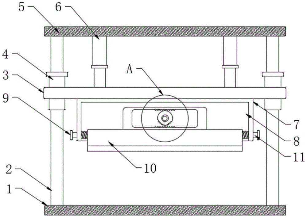
图1为本实用新型提出的一种纸张生产加工用高速分切装置的结构示意图;Fig. 1 is the structural representation of a kind of high-speed slitting device for paper production and processing proposed by the utility model;
图2为图1中的A处结构放大图;Fig. 2 is an enlarged view of the structure at A place in Fig. 1;
图3为本实用新型提出的一种纸张生产加工用高速分切装置的固定板立体图。3 is a perspective view of a fixed plate of a high-speed slitting device for paper production and processing proposed by the utility model.
图中:1底板、2限位杆、3移动板、4套管、5顶板、6电动推杆、7固定板、8凹槽、9限位块、10刀片、11滑动杆、12竖板、13第一齿、14不完全齿轮、15电机。In the picture: 1 bottom plate, 2 limit rod, 3 moving plate, 4 casing, 5 top plate, 6 electric push rod, 7 fixed plate, 8 groove, 9 limit block, 10 blade, 11 sliding rod, 12 vertical plate , 13 first tooth, 14 incomplete gear, 15 motor.
具体实施方式Detailed ways
为使本实用新型的上述目的、特征和优点能够更加明显易懂,下面结合附图对本实用新型的具体实施方式做详细的说明。在下面的描述中阐述了很多具体细节以便于充分理解本实用新型。但是本实用新型能够以很多不同于在此描述的其它方式来实施,本领域技术人员可以在不违背本实用新型内涵的情况下做类似改进,因此本实用新型不受下面公开的具体实施的限制。In order to make the above objects, features and advantages of the present utility model more clearly understood, the specific embodiments of the present utility model are described in detail below with reference to the accompanying drawings. In the following description, numerous specific details are set forth in order to provide a thorough understanding of the present invention. However, the present utility model can be implemented in many other ways different from those described here, and those skilled in the art can make similar improvements without violating the connotation of the present utility model. Therefore, the present utility model is not limited by the specific implementation disclosed below. .
需要说明的是,当元件被称为“固定于”另一个元件,它可以直接在另一个元件上或者也可以存在居中的元件。当一个元件被认为是“连接”另一个元件,它可以是直接连接到另一个元件或者可能同时存在居中元件。本文使用的术语“垂直的”、“水平的”、“左”、“右”以及类似的表只是为了说明的目的,并不表示是唯一的实施方式。It should be noted that when an element is referred to as being "fixed to" another element, it can be directly on the other element or intervening elements may also be present. When an element is referred to as being "connected" to another element, it can be directly connected to the other element or intervening elements may also be present. The terms "vertical", "horizontal", "left", "right" and similar tables used herein are for illustrative purposes only and do not represent the only embodiment.
参照图1-3,一种纸张生产加工用高速分切装置,包括底板1,底板1的上端固定连接有两个对称设置的限位杆2,两个限位杆2的上端共同固定连接有顶板5,两个限位杆2上均滑动套接有套管4,两个套管4上共同固定套接有移动板3。1-3, a high-speed slitting device for paper production and processing, comprising a bottom plate 1, the upper end of the bottom plate 1 is fixedly connected with two symmetrically arranged
顶板5的下端设置有用于对移动板3进行升降的升降机构,升降机构包括固定连接在顶板5下端的两个对称设置的电动推杆6,两个电动推杆6的伸缩端均固定连接在移动板3的上端。The lower end of the
移动板3的下端固定连接有固定板7,固定板7的侧壁上固定连接有电机15,电机15的输出轴末端固定连接在转动杆的端部,固定板7的下端开设有凹槽8,凹槽8的内部滑动连接有刀片10,刀片10的上端固定连接有竖板12,竖板12的内部开设有通槽,凹槽8内设置有用于对刀片10进行移动的移动机构,移动机构包括转动连接在凹槽8内壁上的转动杆,转动杆的端部固定套接有不完全齿轮14,通槽的上下内壁上均固定连接有多个与不完全齿轮14相配合的第一齿13。A
凹槽8内还设置有用于对刀片10进行限位的限位机构,限位机构包括分别固定连接在刀片10两端侧壁上的滑动杆11,两个滑动杆11的端部均固定连接有限位块9,两个滑动杆11位于凹槽8内的部分均套设有弹簧,两个滑动杆11分别穿过固定板7的侧壁并与其滑动连接。The groove 8 is also provided with a limit mechanism for limiting the position of the
本实用新型使用时,当刀片10与纸张接触时,驱动电机15的输出轴转动,带动转动杆以及不完全齿轮14转动,在不完全齿轮14的传动下,竖板12往复移动,从而带动刀片10在凹槽8内往复移动,使得刀片10的下端在纸张上往复移动,实现对纸张进行更加有效的切割,有效的防止纸张未被完全切断的情况发生,提高装置的实用性;When the utility model is in use, when the
在滑动杆11以及弹簧的作用下,能够确保刀片10移动过程中的稳定性,有效的防止刀片10移动的过程中出现偏移,从而影响切割效果。Under the action of the
以上所述,仅为本实用新型较佳的具体实施方式,但本实用新型的保护范围并不局限于此,任何熟悉本技术领域的技术人员在本实用新型揭露的技术范围内,根据本实用新型的技术方案及其实用新型构思加以等同替换或改变,都应涵盖在本实用新型的保护范围之内。The above are only the preferred specific embodiments of the present invention, but the protection scope of the present invention is not limited to this. Equivalent replacement or modification of the new technical solution and its utility model concept shall be included within the protection scope of the present utility model.
Claims (6)
Priority Applications (1)
| Application Number | Priority Date | Filing Date | Title |
|---|---|---|---|
| CN202220606002.5U CN216859849U (en) | 2022-03-18 | 2022-03-18 | High-speed slitting device for paper production and processing |
Applications Claiming Priority (1)
| Application Number | Priority Date | Filing Date | Title |
|---|---|---|---|
| CN202220606002.5U CN216859849U (en) | 2022-03-18 | 2022-03-18 | High-speed slitting device for paper production and processing |
Publications (1)
| Publication Number | Publication Date |
|---|---|
| CN216859849U true CN216859849U (en) | 2022-07-01 |
Family
ID=82124205
Family Applications (1)
| Application Number | Title | Priority Date | Filing Date |
|---|---|---|---|
| CN202220606002.5U Expired - Fee Related CN216859849U (en) | 2022-03-18 | 2022-03-18 | High-speed slitting device for paper production and processing |
Country Status (1)
| Country | Link |
|---|---|
| CN (1) | CN216859849U (en) |
Cited By (1)
| Publication number | Priority date | Publication date | Assignee | Title |
|---|---|---|---|---|
| CN115159234A (en) * | 2022-07-14 | 2022-10-11 | 浙江方邦机械有限公司 | A high-speed slitting machine |
-
2022
- 2022-03-18 CN CN202220606002.5U patent/CN216859849U/en not_active Expired - Fee Related
Cited By (1)
| Publication number | Priority date | Publication date | Assignee | Title |
|---|---|---|---|---|
| CN115159234A (en) * | 2022-07-14 | 2022-10-11 | 浙江方邦机械有限公司 | A high-speed slitting machine |
Similar Documents
| Publication | Publication Date | Title |
|---|---|---|
| CN216859849U (en) | High-speed slitting device for paper production and processing | |
| CN107813179A (en) | A kind of cleaning device for being machined table top | |
| CN215540372U (en) | High-speed dispersion machine for chemical production of high-efficient stirring | |
| CN106363113A (en) | Automatic nail making machine | |
| CN108994909A (en) | A kind of garment material cutting device for processing | |
| CN209453626U (en) | A cutting machine for corrugated paper production | |
| CN220091576U (en) | Agilawood material grinding equipment | |
| CN209364803U (en) | A kind of efficient die-cutting machine | |
| CN216427783U (en) | A cutting knife compatible with positioning function | |
| CN100586671C (en) | A cutting mechanism for automatic production line of honeycomb paper core | |
| CN212352147U (en) | A vertical shred device for sweet potato vermicelli production | |
| CN208604360U (en) | A kind of efficient shearing machine for textile | |
| CN211588821U (en) | A wire cutting device | |
| CN109955294B (en) | A knife-type acrylic plate cutting device | |
| CN210309207U (en) | Corrugated paper creasing device with guide structure | |
| CN221850348U (en) | An environmentally friendly cutting device for producing thermal insulation materials | |
| CN210100669U (en) | Cutting device for plastic uptake forming production line | |
| CN219504899U (en) | Core cutting machine for lead core production | |
| CN221968146U (en) | Rubber seal slitter | |
| CN207642777U (en) | A kind of cleaning device of mechanical processing table top | |
| CN206263174U (en) | automatic nail making machine | |
| CN208408691U (en) | A kind of aluminium alloy short tube cutting mechanism cutter device | |
| CN221912248U (en) | Waste cleaning machine capable of improving production efficiency | |
| CN222902473U (en) | Electronic component processing device | |
| CN209831720U (en) | Novel paper cutting machine transmission structure |
Legal Events
| Date | Code | Title | Description |
|---|---|---|---|
| GR01 | Patent grant | ||
| GR01 | Patent grant | ||
| CF01 | Termination of patent right due to non-payment of annual fee | ||
| CF01 | Termination of patent right due to non-payment of annual fee |
Granted publication date: 20220701 |