CN216856495U - Multistage rotary type agitating unit for nano-material processing - Google Patents
Multistage rotary type agitating unit for nano-material processing Download PDFInfo
- Publication number
- CN216856495U CN216856495U CN202220491383.7U CN202220491383U CN216856495U CN 216856495 U CN216856495 U CN 216856495U CN 202220491383 U CN202220491383 U CN 202220491383U CN 216856495 U CN216856495 U CN 216856495U
- Authority
- CN
- China
- Prior art keywords
- stirring
- multistage rotary
- nano
- supporting plate
- top end
- Prior art date
- Legal status (The legal status is an assumption and is not a legal conclusion. Google has not performed a legal analysis and makes no representation as to the accuracy of the status listed.)
- Active
Links
Images



Landscapes
- Mixers Of The Rotary Stirring Type (AREA)
Abstract
The utility model relates to the technical field of nano material processing, in particular to a multistage rotary stirring device for nano material processing. The stirring drum comprises a U-shaped supporting plate and a stirring drum arranged on the top end of the U-shaped supporting plate, wherein a pair of convex blocks is arranged on the inner side of the U-shaped supporting plate, a clamping groove is formed between the two convex blocks, a bottom sleeve is arranged at the bottom end of the stirring drum, a servo motor is arranged at the inner end of the bottom sleeve, a turntable is coaxially connected to the top end of the servo motor, a plurality of stirring rods are arranged on the top end of the turntable, an outer ring is arranged on the outer side of the stirring drum, rotating shafts are arranged on two sides of the outer ring, and the rotating shafts are connected with the U-shaped supporting plate in a rotating mode. According to the utility model, the servo motor drives the rotary table to rotate, the rotary table drives the stirring rods to stir the nano materials contained in the inner end of the stirring cylinder, and meanwhile, the outer side of the stirring cylinder and the U-shaped support plate keep relative rotation, so that the stirring cylinder can be integrally turned over, the nano materials at the inner end are fully and uniformly shaken, and the stirring effect is further improved.
Description
Technical Field
The utility model relates to the technical field of nano material processing, in particular to a multistage rotary stirring device for nano material processing.
Background
The nano material is a material which has at least one dimension in a three-dimensional space in a nano size or is formed by taking the nano size or the nano size as a basic unit, and the nano material is about equivalent to the dimension of 10-1000 atoms which are closely arranged together.
Nanometer material need be through multichannel process when carrying out the use, because nanometer material is the combined material mostly, need carry out intensive mixing to it before using, and stirring device is used in the processing of current nanometer material adopts the inside stirring formula to stir processing mostly, and the stirring in-process, the nanometer material that is located the top is hardly by intensive mixing, stirring effect greatly reduced need process many times, just can be to its intensive mixing.
SUMMERY OF THE UTILITY MODEL
The utility model aims to provide a multistage rotary stirring device for processing nano materials, which is used for solving the problems in the background technology.
In order to achieve the purpose, the utility model provides a multistage rotary stirring device for processing a nano material, which comprises a U-shaped supporting plate and a stirring cylinder arranged at the top end of the U-shaped supporting plate, wherein a pair of convex blocks are arranged on the inner side of the U-shaped supporting plate, a clamping groove is formed between the two convex blocks, a bottom sleeve is arranged at the bottom end of the stirring cylinder, a servo motor is arranged at the inner end of the bottom sleeve, a clamping plate is arranged at the bottom end of the bottom sleeve and is in clamping fit with the clamping groove, a rotary table is coaxially connected to the top end of the servo motor, a plurality of stirring rods are arranged at the top end of the rotary table, an outer ring is arranged on the outer side of the stirring cylinder, rotating shafts are arranged on two sides of the outer ring, the rotating shafts are rotatably connected with the top end of the side surface of the U-shaped supporting plate, a top sleeve is rotatably connected to the top end of the stirring cylinder, and a top plug is in inserting fit with the top sleeve.
As a further improvement of the technical scheme, a pair of jacks is formed in two sides of the protruding block, the inner ends of the jacks are in splicing fit with U-shaped insertion rods, the U-shaped insertion rods and two sides of the bottom end of the protruding block are in splicing fit with stop blocks, a pair of reset springs are connected to the bottom ends of the stop blocks, and the two reset springs are arranged on two sides of the clamping plate respectively.
As a further improvement of the technical scheme, side plates are arranged on two sides of the U-shaped supporting plate.
As a further improvement of the technical scheme, the bottom end of the bottom sleeve is provided with a plurality of ventilation grooves.
As a further improvement of the technical scheme, a side ring is arranged on the outer side of the rotary table.
As a further improvement of the technical scheme, a plurality of salient points are arranged on the outer side of the stirring rod.
Compared with the prior art, the utility model has the beneficial effects that:
1. among this multistage rotary type agitating unit for nano-material processing, servo motor drives the carousel and rotates, and the carousel drives each puddler and stirs the nano-material that holds in the churn the inner and handle, keeps rotating relatively between the churn outside and the U type backup pad simultaneously for the churn can wholly overturn, fully shakes the even to the nano-material of inner, further improves stirring effect.
2. Among this multistage rotary type agitating unit for nano-material processing, rise from top to bottom through the dog, inject cardboard amplitude of oscillation, avoid cardboard amplitude of oscillation too big, lead to the nano-material of the inner splendid attire of churn to scatter and splash all around, hardly obtain the intensive mixing.
Drawings
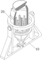
FIG. 1 is a schematic view of the overall structure of embodiment 1 of the present invention;
FIG. 2 is a sectional view showing the whole structure of embodiment 1 of the present invention;
FIG. 3 is a sectional view of a U-shaped supporting plate according to embodiment 1 of the present invention;
FIG. 4 is an enlarged view of a portion of FIG. 3A according to embodiment 1 of the present invention;
FIG. 5 is a sectional view of a mixing drum according to embodiment 1 of the present invention, with the structure being disassembled;
fig. 6 is a partially enlarged view of the portion B in fig. 5 according to embodiment 1 of the present invention.
The various reference numbers in the figures mean:
10. a U-shaped support plate; 110. a bump; 111. a card slot; 112. a jack; 113. a stopper; 114. a return spring; 120. a U-shaped inserted link; 130. a side plate;
20. a mixing drum; 210. a bottom cover; 211. a ventilation groove; 212. clamping a plate; 220. a servo motor; 230. a turntable; 231. a side ring; 240. a stirring rod; 241. salient points; 250. an outer ring; 251. a rotating shaft; 260. jacking and sleeving; 261. and (7) plugging the top.
Detailed Description
The technical solutions in the embodiments of the present invention will be clearly and completely described below with reference to the drawings in the embodiments of the present invention, and it is obvious that the described embodiments are only a part of the embodiments of the present invention, and not all of the embodiments. All other embodiments, which can be derived by a person skilled in the art from the embodiments given herein without making any creative effort, shall fall within the protection scope of the present invention.
In the description of the present invention, it is to be understood that the terms "center", "longitudinal", "lateral", "length", "width", "thickness", "upper", "lower", "front", "rear", "left", "right", "vertical", "horizontal", "top", "bottom", "inner", "outer", "clockwise", "counterclockwise", and the like, indicate orientations and positional relationships based on those shown in the drawings, and are used only for convenience of description and simplicity of description, and do not indicate or imply that the equipment or element being referred to must have a particular orientation, be constructed and operated in a particular orientation, and thus, should not be considered as limiting the present invention.
Furthermore, the terms "first", "second" and "first" are used for descriptive purposes only and are not to be construed as indicating or implying relative importance or implicitly indicating the number of technical features indicated. Thus, a feature defined as "first" or "second" may explicitly or implicitly include one or more of that feature. In the description of the present invention, "a plurality" means two or more unless specifically defined otherwise.
Example 1
Referring to fig. 1-6, the present invention provides a multistage rotation type stirring device for processing a nano material, including a U-shaped support plate 10 and a stirring barrel 20 installed at the top end of the U-shaped support plate 10, a pair of protrusions 110 is installed inside the U-shaped support plate 10, a slot 111 is installed between the two protrusions 110, a bottom sleeve 210 is installed at the bottom end of the stirring barrel 20, a servo motor 220 is installed at the inner end of the bottom sleeve 210, a clamping plate 212 is installed at the bottom end of the bottom sleeve 210, the clamping plate 212 is in clamping fit with the slot 111, a turntable 230 is coaxially connected to the top end of the servo motor 220, a plurality of stirring rods 240 are installed at the top end of the turntable 230, an outer ring 250 is installed outside the stirring barrel 20, rotating shafts 251 are installed at both sides of the outer ring 250, the rotating shafts 251 are rotatably connected to the top end of the side surface of the U-shaped support plate 10, a top sleeve 260 is rotatably connected to the top end of the stirring barrel 20, and a top plug 261 is inserted and fitted to the top end of the top sleeve.
During the specific use, extract top stopper 261, the nanomaterial that will process drops into churn 20 the inner along top cover 260 top, open servo motor 220, servo motor 220 drives carousel 230 and rotates, carousel 230 drives each puddler 240 and rotates, puddler 240 rotates the in-process and stirs the processing to the nanomaterial, and simultaneously, use pivot 251 to carry out reciprocating swing to whole churn 20 as the axle, make a round trip to alternate between cardboard 212 and the draw-in groove 111, make the nanomaterial of churn 20 the inner fully shake evenly, further improve nanomaterial processing effect.
In order to further improve the processing efficiency of the nano material, in this embodiment, a pair of insertion holes 112 are formed on both sides of the bump 110, the inner ends of the insertion holes 112 are inserted and matched with the U-shaped insertion rod 120, and the U-shaped insertion rod 120 is inserted and matched with the side surface of the clamping plate 212. During specific use, after shaking uniformly, the U-shaped inserted bar 120 is inserted into the inner end of the insertion hole 112 and penetrates through the side surface of the clamping plate 212, so that the bottom end of the clamping plate 212 is fixedly connected with the inner end of the clamping groove 111, the mixing drum 20 is in a static state at the moment, the free fixing function of the mixing drum 20 is realized, and the processing efficiency of the nano material is further improved.
In order to avoid the too large swing amplitude of the catch plate 212, furthermore, the two sides of the bottom end of the catch groove 111 are respectively inserted and matched with a stop 113, the bottom end of the stop 113 is connected with a pair of return springs 114, and the two return springs 114 are respectively arranged on the two sides of the catch plate 212. During the specific use, cardboard 212 can extrude dog 113 in draw-in groove 111 inner swing in-process, and dog 113 receives the extrusion back, extrudees reset spring 114 downwards, moves up and down through dog 113, prescribes a limit to cardboard 212 amplitude of oscillation, avoids cardboard 212 amplitude of oscillation too big, leads to the nano-material of 20 inner splendid attire to scatter and splash all around, hardly obtains intensive mixing.
In order to increase the stability of the whole device, specifically, the U-shaped support plate 10 is provided with side plates 130 at both sides. When the device is used specifically, a triangular structure is formed between the side plate 130 and the U-shaped support plate 10, so that the stability of the two sides of the U-shaped support plate 10 is improved, and the stability of the whole device is increased.
In order to keep the inner end of the bottom cover 210 in air communication with the outside, in addition, the bottom end of the bottom cover 210 is provided with a plurality of ventilation grooves 211. Make the inner air current that keeps with the external world of end cover 210 through the ventilative groove 211 that sets up, avoid servo motor 220 long-term operation to produce the unable heat of getting rid of, lead to the inner stable continuous rising of end cover 210, influence servo motor 220 normal operating very easily, lead to servo motor 220 to appear damaging even.
In addition, a side ring 231 is disposed outside the turntable 230 to further improve the stirring effect of the nanomaterial. The nanomaterial that holds is stirred to carousel 230 border through the side ring 231 that sets up, further improves nanomaterial stirring effect.
In order to improve the mixing effect of the nano-materials, in particular, a plurality of salient points 241 are arranged outside the stirring rod 240. The contact area between the stirring rod 240 and the nano material is increased through the arranged salient points 241, and the mixing effect of the nano material is improved.
The multistage rotary type agitating unit for nano-material processing of this embodiment is when specifically using, extract top stopper 261, the nano-material that will carry out processing drops into churn 20 the inner along top cover 260 top, open servo motor 220, servo motor 220 drives carousel 230 and rotates, carousel 230 drives each puddler 240 and rotates, puddler 240 rotates the in-process and stirs the processing to nano-material, and simultaneously, extract U type inserted bar 120, it is fixed to make cardboard 212 and draw-in groove 111 support lose, use pivot 251 to carry out reciprocating swing to whole churn 20 as the axle, alternate back and forth between cardboard 212 and the draw-in groove 111, make the nano-material of churn 20 the inner fully shake evenly, further improve nano-material processing effect.
The foregoing shows and describes the general principles, principal features, and advantages of the utility model. It will be understood by those skilled in the art that the present invention is not limited to the embodiments described above, and the preferred embodiments of the present invention are described in the above embodiments and the description, and are not intended to limit the present invention. The scope of the utility model is defined by the appended claims and equivalents thereof.
Claims (7)
1. The utility model provides a multistage rotary type agitating unit for nano-material processing, includes U type backup pad (10) and installs churn (20) on U type backup pad (10) top, its characterized in that: a pair of convex blocks (110) are arranged on the inner side of the U-shaped supporting plate (10), a clamping groove (111) is arranged between the two convex blocks (110), a bottom sleeve (210) is arranged at the bottom end of the mixing drum (20), a servo motor (220) is arranged at the inner end of the bottom sleeve (210), the bottom end of the bottom sleeve (210) is provided with a clamping plate (212), the clamping plate (212) is in clamping fit with the clamping groove (111), the top end of the servo motor (220) is coaxially connected with a turntable (230), the top end of the turntable (230) is provided with a plurality of stirring rods (240), an outer ring (250) is arranged on the outer side of the mixing drum (20), rotating shafts (251) are arranged on two sides of the outer ring (250), the rotating shaft (251) is rotatably connected with the top end of the side surface of the U-shaped supporting plate (10), the top end of the mixing drum (20) is rotatably connected with a top sleeve (260), and a top plug (261) is inserted and matched with the top end of the top sleeve (260).
2. The multistage rotary stirring device for nanomaterial processing according to claim 1, wherein: a pair of jacks (112) are formed in two sides of the projection (110), U-shaped inserting rods (120) are in inserting fit with the inner ends of the jacks (112), and the U-shaped inserting rods (120) are in inserting fit with the side faces of the clamping plates (212).
3. The multistage rotary stirring device for nanomaterial processing of claim 2, wherein: the clamping device is characterized in that two sides of the bottom end of the clamping groove (111) are respectively in inserted fit with a stop block (113), the bottom end of the stop block (113) is connected with a pair of return springs (114), and the two return springs (114) are respectively arranged on two sides of the clamping plate (212).
4. The multistage rotary stirring device for nanomaterial processing of claim 1, wherein: both sides of the U-shaped supporting plate (10) are provided with side plates (130).
5. The multistage rotary stirring device for nanomaterial processing of claim 1, wherein: the bottom end of the bottom sleeve (210) is provided with a plurality of ventilation grooves (211).
6. The multistage rotary stirring device for nanomaterial processing of claim 1, wherein: and a side ring (231) is arranged on the outer side of the rotating disc (230).
7. The multistage rotary stirring device for nanomaterial processing of claim 1, wherein: a plurality of salient points (241) are arranged on the outer side of the stirring rod (240).
Priority Applications (1)
| Application Number | Priority Date | Filing Date | Title |
|---|---|---|---|
| CN202220491383.7U CN216856495U (en) | 2022-03-09 | 2022-03-09 | Multistage rotary type agitating unit for nano-material processing |
Applications Claiming Priority (1)
| Application Number | Priority Date | Filing Date | Title |
|---|---|---|---|
| CN202220491383.7U CN216856495U (en) | 2022-03-09 | 2022-03-09 | Multistage rotary type agitating unit for nano-material processing |
Publications (1)
| Publication Number | Publication Date |
|---|---|
| CN216856495U true CN216856495U (en) | 2022-07-01 |
Family
ID=82160492
Family Applications (1)
| Application Number | Title | Priority Date | Filing Date |
|---|---|---|---|
| CN202220491383.7U Active CN216856495U (en) | 2022-03-09 | 2022-03-09 | Multistage rotary type agitating unit for nano-material processing |
Country Status (1)
| Country | Link |
|---|---|
| CN (1) | CN216856495U (en) |
Cited By (2)
| Publication number | Priority date | Publication date | Assignee | Title |
|---|---|---|---|---|
| CN115178147A (en) * | 2022-09-09 | 2022-10-14 | 山东鼎泰盛机械科技有限公司 | Multifunctional paint stirring equipment for spraying paint |
| CN116512428A (en) * | 2023-03-21 | 2023-08-01 | 万宁大丰收实业有限公司 | A high-strength anti-permeability concrete production device |
-
2022
- 2022-03-09 CN CN202220491383.7U patent/CN216856495U/en active Active
Cited By (2)
| Publication number | Priority date | Publication date | Assignee | Title |
|---|---|---|---|---|
| CN115178147A (en) * | 2022-09-09 | 2022-10-14 | 山东鼎泰盛机械科技有限公司 | Multifunctional paint stirring equipment for spraying paint |
| CN116512428A (en) * | 2023-03-21 | 2023-08-01 | 万宁大丰收实业有限公司 | A high-strength anti-permeability concrete production device |
Similar Documents
| Publication | Publication Date | Title |
|---|---|---|
| CN217617680U (en) | Energy-saving shakeout machine | |
| CN210925409U (en) | University student's community activity is with multi-functional display device | |
| CN212417674U (en) | Coating stirring kettle | |
| CN113294982A (en) | A drying machine equipment for agricultural product is stored | |
| CN221760242U (en) | Support mechanism and clothes dryer | |
| CN206715813U (en) | A kind of movable dispersion machine rabbling mechanism | |
| CN214973564U (en) | Agitated vessel with adjustable | |
| CN214089575U (en) | Highway signboard | |
| CN115155402A (en) | An anti-precipitation kit with homogenization function | |
| CN215028184U (en) | Mixing arrangement is used in animal feed production | |
| CN211593012U (en) | Shaking type bagging machine | |
| CN216799498U (en) | A kind of graphite production dispersing machine | |
| CN214585290U (en) | General procalcitonin determination kit | |
| CN212433999U (en) | VR parachuting simulation bearing support easy to assemble | |
| CN222636145U (en) | Decontamination testing machine | |
| CN218573556U (en) | Powder dispersibility test equipment | |
| CN223574072U (en) | Seal convenient for replacing seal head | |
| CN211754252U (en) | Agitating unit of rapid stabilization centre gripping | |
| CN217795769U (en) | Small-size compounding mixer | |
| CN214863344U (en) | Based on automatic control formula pharmacy device that sways | |
| CN222139061U (en) | A two-dimensional mixer | |
| CN213253996U (en) | Mixing and stirring device | |
| CN212843914U (en) | electronic scale | |
| CN223261014U (en) | USB side plug connector female seat | |
| CN215389056U (en) | High-efficient proportioning machine of benefit clay |
Legal Events
| Date | Code | Title | Description |
|---|---|---|---|
| GR01 | Patent grant | ||
| GR01 | Patent grant |