CN216841697U - Unsmooth falcon section of jurisdiction is assembled and is prevented damaged device - Google Patents
Unsmooth falcon section of jurisdiction is assembled and is prevented damaged device Download PDFInfo
- Publication number
- CN216841697U CN216841697U CN202123019805.5U CN202123019805U CN216841697U CN 216841697 U CN216841697 U CN 216841697U CN 202123019805 U CN202123019805 U CN 202123019805U CN 216841697 U CN216841697 U CN 216841697U
- Authority
- CN
- China
- Prior art keywords
- piece
- falcon
- supporting seat
- jurisdiction
- section
- Prior art date
- Legal status (The legal status is an assumption and is not a legal conclusion. Google has not performed a legal analysis and makes no representation as to the accuracy of the status listed.)
- Active
Links
Images


Landscapes
- Jib Cranes (AREA)
Abstract
The utility model discloses an anti-damage device is assembled to unsmooth falcon section of jurisdiction, including supporting seat, hydraulic telescoping rod and motor, the upper left end welded connection of supporting seat has first connecting piece, first connecting axle fixed connection is at the lower extreme of connecting strip, regulating block swing joint is in orbital inside, the right-hand member fixedly connected with hydraulic telescoping rod of regulating block, both ends rotate about between the connecting strip monomer and are connected with first pivot, the articulated loading board that is connected with in the upper right end of connecting strip, the inside swing joint of second connecting axle has the second connecting piece, the upper end of loading board is rotated and is connected with the connecting roll, and the right-hand member of connecting roll installs the motor, the upper end integration of connecting roll is connected with support piece, and the upper end fixedly connected with installation pole of spacing cover. This breakage-proof device is assembled to unsmooth falcon section of jurisdiction, the height-adjusting of being convenient for, and the easy stable concatenation section of jurisdiction to it is damaged when preventing that the section of jurisdiction from assembling.
Description
Technical Field
The utility model relates to a relevant technical field of unsmooth falcon section of jurisdiction specifically is an anti-damage device is assembled to unsmooth falcon section of jurisdiction.
Background
Along with the development of modern science and technology, the quantity in various tunnels also is increasing gradually, and during tunnel construction, in order to prevent that the tunnel that has excavated from causing the earth's surface to subside the scheduling problem, need utilize the prefabricated section of jurisdiction of assembling the device in the tunnel installation, therefore the section of jurisdiction is indispensable component part in the tunnel, and the section of jurisdiction pattern on the market is various at present, and the tongue and groove section of jurisdiction is one of them pattern.
However, general unsmooth falcon section of jurisdiction assembly device is not convenient for height-adjusting, is difficult to stabilize the concatenation section of jurisdiction, and the section of jurisdiction is damaged easily when assembling, the utility model aims to provide an anti-damage device is assembled to unsmooth falcon section of jurisdiction to solve the problem that above-mentioned background art provided.
Disclosure of Invention
An object of the utility model is to provide an anti-damage device is assembled to unsmooth falcon section of jurisdiction to solve most of unsmooth falcon section of jurisdiction assembly devices that provide in the above-mentioned background art, the height-adjusting of being not convenient for, and be difficult to stabilize the concatenation section of jurisdiction, and easy damaged problem when the section of jurisdiction is assembled.
In order to achieve the above object, the utility model provides a following technical scheme: a concave-convex tenon pipe piece assembling breakage-proof device comprises a supporting seat, a hydraulic telescopic rod and a motor, wherein the left upper end of the supporting seat is welded and connected with a first connecting piece, the inside of the first connecting piece is movably connected with a first connecting shaft, the first connecting shaft is fixedly connected with the lower end of a connecting strip, the middle end of the first connecting shaft is rotatably connected with an adjusting block, the adjusting block is movably connected inside a track, the track is arranged inside the upper end of the supporting seat, the right end of the adjusting block is fixedly connected with the hydraulic telescopic rod, the hydraulic telescopic rod is in bolted connection with the upper end of the supporting seat, the left end and the right end between connecting strip monomers are rotatably connected with a first rotating shaft, the middle end between the connecting strip monomers is connected with a second rotating shaft, the right upper end of the connecting strip is hinged and connected with a bearing plate, and the left lower end of the bearing plate is welded and connected with a second connecting shaft, the inside swing joint of second connecting axle has the second connecting piece, and second connecting piece fixed connection is in the upper left end of connecting strip, the upper end of loading board is rotated and is connected with the connecting roller, and the right-hand member of connecting roller installs the motor, the upper end integration of connecting roller is connected with support piece, and the upper end fixedly connected with installation pole of stop collar to threaded connection has the stop collar on the installation pole.
Preferably, the first connecting pieces are symmetrically arranged front and back about a longitudinal central axis of the supporting seat, the first connecting pieces are in one-to-one correspondence with the second connecting shafts up and down, and the longitudinal cross sections of the second connecting shafts and the first connecting pieces are in a shape like a Chinese character 'hui'.
Preferably, the adjusting block and the right end of the supporting seat form a telescopic structure through a rail, the longitudinal section of the adjusting block is T-shaped, and the adjusting block is matched with the rail.
Preferably, the bearing plate forms a lifting structure with the supporting seat through the connecting strip, and the second connecting shaft and the second connecting piece connected with the left lower end of the bearing plate and the first connecting piece and the first connecting shaft form a sliding structure.
Preferably, the support members are disposed in bilateral symmetry about a longitudinal central axis of the connecting roller, and the upper end of the support members have an arc-shaped longitudinal section, and the mounting bars are disposed at equal angles about the center of the support members.
Preferably, the stop collar includes inlayer and rubber layer, and inlayer threaded connection is on the installation pole, and the outer wall fixedly connected with rubber layer of inlayer.
Compared with the prior art, the beneficial effects of the utility model are that: the concave-convex tenon duct piece assembling anti-damage device is convenient for adjusting the height, is easy to stably assemble duct pieces and prevents the duct pieces from being damaged during assembling;
1. the hydraulic telescopic rod is provided with a connecting strip and a first connecting shaft, and the adjusting block and the right end of the supporting seat are structurally designed, so that when the hydraulic telescopic rod drives the adjusting block to slide left and right, the first connecting shaft and the second connecting piece respectively slide left and right in the first connecting piece and the second connecting shaft;
2. the duct piece splicing device is provided with a supporting piece and a connecting roller, wherein the supporting piece is arranged in a left-right symmetrical mode about a longitudinal central axis of the connecting roller, so that a limiting sleeve on the supporting piece supports the left end and the right end of a duct piece, and an installation rod is arranged in an equiangular mode about the center of the supporting piece, so that the limiting sleeve uniformly penetrates into the duct piece, and the duct piece is easily and stably spliced;
3. be equipped with rubber layer and inlayer, the threaded connection of inlayer and installation pole for the inlayer is installed on the installation pole, and fixedly connected with rubber layer on the outer wall of inlayer makes the rubber layer protect the inside of section of jurisdiction, prevents that the stop collar from causing the section of jurisdiction damage.
Drawings
FIG. 1 is a schematic view of the front view structure of the present invention;
FIG. 2 is a schematic view of the structure of the stop collar of the present invention;
FIG. 3 is a schematic diagram of the right side view of the cross-sectional structure of the present invention;
fig. 4 is the utility model discloses profile structure schematic diagram is looked on left side to stop collar and installation pole connection.
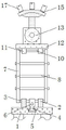
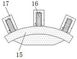
In the figure: 1. a supporting base; 2. a first connecting member; 3. a first connecting shaft; 4. an adjusting block; 5. a track; 6. a hydraulic telescopic rod; 7. a connecting strip; 8. a first rotating shaft; 9. a second rotating shaft; 10. a second connecting member; 11. a second connecting shaft; 12. a carrier plate; 13. a connecting roller; 14. a motor; 15. a support member; 16. mounting a rod; 17. a limiting sleeve; 1701. an inner layer; 1702. a rubber layer.
Detailed Description
The technical solution in the embodiments of the present invention will be clearly and completely described below with reference to the drawings in the embodiments of the present invention, and it is obvious that the described embodiments are only some embodiments of the present invention, rather than all embodiments, and all other embodiments obtained by a person of ordinary skill in the art without creative work belong to the protection scope of the present invention based on the embodiments of the present invention.
Referring to fig. 1-4, the present invention provides a technical solution: a concave-convex tenon pipe piece assembling breakage-proof device comprises a supporting seat 1, a first connecting piece 2, a first connecting shaft 3, an adjusting block 4, a track 5, a hydraulic telescopic rod 6, a connecting strip 7, a first rotating shaft 8, a second rotating shaft 9, a second connecting piece 10, a second connecting shaft 11, a bearing plate 12, a connecting roller 13, a motor 14, a supporting piece 15, a mounting rod 16 and a limiting sleeve 17, wherein the upper left end of the supporting seat 1 is connected with the first connecting piece 2 in a welding mode, the first connecting shaft 3 is movably connected inside the first connecting piece 2, the first connecting shaft 3 is fixedly connected to the lower end of the connecting strip 7, the adjusting block 4 is rotatably connected to the middle end of the first connecting shaft 3, the adjusting block 4 is movably connected inside the track 5, the track 5 is arranged inside the upper end of the supporting seat 1, the hydraulic telescopic rod 6 is fixedly connected to the right end of the adjusting block 4, and the hydraulic telescopic rod 6 is in bolted connection with the upper end of the supporting seat 1, both ends are rotated about between 7 monomers of connecting strip and are connected with first pivot 8, and the middle-end between 7 monomers of connecting strip is connected through second pivot 9, the articulated loading board 12 that is connected with in upper right end of connecting strip 7, and the left lower extreme welded connection of loading board 12 has second connecting axle 11, the inside swing joint of second connecting axle 11 has second connecting piece 10, and second connecting piece 10 fixed connection is in the upper left end of connecting strip 7, the upper end of loading board 12 is rotated and is connected with connecting roller 13, and connecting roller 13's right-hand member installs motor 14, connecting roller 13's upper end integration is connected with support piece 15, and the upper end fixedly connected with installation pole 16 of stop collar 17, and threaded connection has stop collar 17 on the installation pole 16.
As shown in fig. 1 and 3, the first connecting pieces 2 are symmetrically arranged in front and back directions about the longitudinal central axis of the supporting seat 1, the positions of the first connecting pieces 2 and the second connecting shafts 11 are in up-down one-to-one correspondence, the longitudinal cross-sectional shapes of the second connecting shafts 11 and the first connecting pieces 2 are in a shape of 'return', the positions of the first connecting pieces 2 and the second connecting shafts 11 are designed to stably support the supporting plate 12, the second connecting pieces 10 and the first connecting shafts 3 can move left and right inside the second connecting shafts 11 and the first connecting pieces 2, the adjusting block 4 forms a telescopic structure with the right end of the supporting seat 1 through the rail 5, the longitudinal cross-sectional shape of the adjusting block 4 is in a shape of 'T', the adjusting block 4 is matched with the rail 5, the adjusting block 4 can slide left and right inside the rail 5 to adjust the position on the supporting seat 1, so as to prevent the adjusting block 4 from being separated from the rail 5, the supporting plate 12 forms a lifting structure with the supporting seat 1 through the connecting strip 7, the second connecting shaft 11 and the second connecting piece 10 connected with the left lower end of the bearing plate 12 and the first connecting piece 2 and the first connecting shaft 3 form a sliding structure, the bearing plate 12 can be lifted and adjusted to be spaced from the supporting seat 1 when the single connecting strips 7 stretch out and draw back, and the second connecting piece 10 and the first connecting shaft 3 can respectively slide left and right in the second connecting shaft 11 and the first connecting piece 2;
as shown in fig. 1 and 4, the supporting members 15 are arranged in bilateral symmetry about the longitudinal central axis of the connecting roller 13, the longitudinal section of the upper end of the supporting member 15 is arc-shaped, the mounting rods 16 are arranged at equal angles about the center of the supporting member 15, the supporting members 15 are arranged at the left end and the right end of the connecting roller 13, so that the upper end of the supporting member 15 can be fitted to the lower end of the tube sheet, and the mounting rods 16 are uniformly arranged at the upper end of the supporting member 15;
as shown in the figures 2 and 4, the stop collar 17 comprises an inner layer 1701 and a rubber layer 1702, wherein the inner layer 1701 is screwed on the mounting rod 16, the rubber layer 1702 is fixedly connected to the outer wall of the inner layer 1701, the inner layer 1701 can be replaced, and the rubber layer 1702 wraps the outer surface of the inner layer 1701 to protect the inside of the pipe sheet.
The working principle is as follows: when the anti-damage device is assembled by using the concave-convex tenon segments, the segments are placed at the upper ends of the supporting pieces 15 by combining the drawings of fig. 1 and 3, the limiting sleeves 17 which are distributed at equal angles correspond to the connecting holes formed in the lower ends of the segments, the supporting pieces 15 are symmetrically arranged on the left and right sides of the longitudinal central axis of the connecting roller 13, so that the left and right ends of the segments can be supported between the supporting pieces 15, the segments can be stably limited on the supporting pieces 15, the motor 14 drives the connecting roller 13 to rotate when in work, the position of the supporting pieces 15 is adjusted, and the segments are installed at different positions of a tunnel;
with reference to fig. 2 and 4, the inner layer 1701 is screwed on the mounting rod 16, the inner layer 1701 is mounted on the support 15, and the rubber layer 1702 is fixedly connected to the outer wall of the inner layer 1701, so that when the inner layer 1701 penetrates through the connecting hole formed in the duct piece, the rubber layer 1702 protects the connecting hole and prevents the limiting sleeve 17 from damaging the connecting hole of the duct piece;
combine fig. 1 and fig. 2, when the height of section of jurisdiction needs to be adjusted, 6 work of hydraulic telescoping rod promote regulating block 4 horizontal slip in track 5, make first connecting axle 3 horizontal slip in first connecting piece 2, let between the connecting strip 7 monomer stretch out and draw back through first pivot 8 and second pivot 9, let second connecting piece 10 horizontal slip in second connecting axle 11, connecting strip 7 of upper right end rotates at the right lower extreme of loading board 12, thereby drive loading board 12 through connecting strip 7 and go up and down, be convenient for adjust the height of section of jurisdiction, this is exactly this operating principle that the damage device was assembled to unsmooth falcon section of jurisdiction.
The utility model discloses the standard part that uses all can purchase from the market, and dysmorphism piece all can be customized according to the description with the record of drawing of description, and the concrete connected mode of each part all adopts conventional means such as ripe bolt, rivet, welding among the prior art, and machinery, part and equipment all adopt among the prior art, and conventional model, including the conventional connected mode among the circuit connection adoption prior art, and the details are not repeated here, and the content that does not make detailed description in this description belongs to the prior art that skilled person in the art knows.
Although the present invention has been described in detail with reference to the foregoing embodiments, it will be apparent to those skilled in the art that modifications may be made to the embodiments or portions thereof without departing from the spirit and scope of the invention.
Claims (6)
1. The utility model provides an anti-damage device is assembled to unsmooth falcon section of jurisdiction, includes supporting seat (1), hydraulic telescoping rod (6) and motor (14), its characterized in that: the left upper end of the supporting seat (1) is connected with a first connecting piece (2) in a welding mode, the inner portion of the first connecting piece (2) is movably connected with a first connecting shaft (3), the first connecting shaft (3) is fixedly connected to the lower end of a connecting strip (7), the middle end of the first connecting shaft (3) is rotatably connected with an adjusting block (4), the adjusting block (4) is movably connected to the inner portion of a track (5), the track (5) is arranged in the upper end of the supporting seat (1), the right end of the adjusting block (4) is fixedly connected with a hydraulic telescopic rod (6), the hydraulic telescopic rod (6) is connected to the upper end of the supporting seat (1) in a bolt mode, the left end and the right end of the connecting strip (7) between the single bodies are rotatably connected with a first rotating shaft (8), the middle end of the connecting strip (7) between the single bodies is connected with a second rotating shaft (9), and the right upper end of the connecting strip (7) is hinged with a bearing plate (12), and the left lower extreme welded connection of loading board (12) has second connecting axle (11), the inside swing joint of second connecting axle (11) has second connecting piece (10), and second connecting piece (10) fixed connection is in the upper left end of connecting strip (7), the upper end of loading board (12) is rotated and is connected with connecting roller (13), and the right-hand member of connecting roller (13) installs motor (14), the upper end integration of connecting roller (13) is connected with support piece (15), and the upper end fixedly connected with installation pole (16) of stop collar (17) to threaded connection has stop collar (17) on installation pole (16).
2. The uneven falcon segment assembling breakage prevention device of claim 1, wherein: the first connecting pieces (2) are symmetrically arranged front and back about a longitudinal central axis of the supporting seat (1), the first connecting pieces (2) are in one-to-one correspondence with the second connecting shafts (11) up and down, and the second connecting shafts (11) and the first connecting pieces (2) are in a shape of a Chinese character 'hui'.
3. The uneven falcon segment assembling breakage prevention device of claim 1, wherein: the adjusting block (4) and the right end of the supporting seat (1) form a telescopic structure through the rail (5), the longitudinal section of the adjusting block (4) is T-shaped, and the adjusting block (4) is matched with the rail (5).
4. The uneven falcon segment assembling breakage prevention device of claim 1, wherein: the bearing plate (12) and the supporting seat (1) form a lifting structure through the connecting strip (7), and the second connecting shaft (11) and the second connecting piece (10) which are connected with the left lower end of the bearing plate (12) and the first connecting piece (2) and the first connecting shaft (3) form a sliding structure.
5. The uneven falcon segment assembling breakage prevention device of claim 1, wherein: the supporting pieces (15) are arranged in bilateral symmetry about the longitudinal central axis of the connecting roller (13), the upper end longitudinal section of each supporting piece (15) is arc-shaped, and the mounting rods (16) are arranged at equal angles about the center of each supporting piece (15).
6. The uneven falcon segment assembling breakage prevention device of claim 1, wherein: the stop collar (17) comprises an inner layer (1701) and a rubber layer (1702), wherein the inner layer (1701) is in threaded connection with the mounting rod (16), and the rubber layer (1702) is fixedly connected to the outer wall of the inner layer (1701).
Priority Applications (1)
| Application Number | Priority Date | Filing Date | Title |
|---|---|---|---|
| CN202123019805.5U CN216841697U (en) | 2021-12-03 | 2021-12-03 | Unsmooth falcon section of jurisdiction is assembled and is prevented damaged device |
Applications Claiming Priority (1)
| Application Number | Priority Date | Filing Date | Title |
|---|---|---|---|
| CN202123019805.5U CN216841697U (en) | 2021-12-03 | 2021-12-03 | Unsmooth falcon section of jurisdiction is assembled and is prevented damaged device |
Publications (1)
| Publication Number | Publication Date |
|---|---|
| CN216841697U true CN216841697U (en) | 2022-06-28 |
Family
ID=82104441
Family Applications (1)
| Application Number | Title | Priority Date | Filing Date |
|---|---|---|---|
| CN202123019805.5U Active CN216841697U (en) | 2021-12-03 | 2021-12-03 | Unsmooth falcon section of jurisdiction is assembled and is prevented damaged device |
Country Status (1)
| Country | Link |
|---|---|
| CN (1) | CN216841697U (en) |
-
2021
- 2021-12-03 CN CN202123019805.5U patent/CN216841697U/en active Active
Similar Documents
| Publication | Publication Date | Title |
|---|---|---|
| CN103522272B (en) | A kind of automobile chassis workpiece auxiliary assembling apparatus | |
| CN212773348U (en) | Scaffold for building construction | |
| CN216841697U (en) | Unsmooth falcon section of jurisdiction is assembled and is prevented damaged device | |
| CN204778700U (en) | Hole hole protection architecture's aerial working platform | |
| CN215633041U (en) | Connecting rod structure, working arm and tunnel arch-form machine | |
| CN212342358U (en) | Draw gear for cable manufacture that can stabilize spacing | |
| CN210123868U (en) | Cable bracket | |
| CN211790359U (en) | Installation tool for distribution cabinet door | |
| CN210430814U (en) | Bracket arm for cable bridge | |
| CN109680112B (en) | Blast furnace shell cooling wall installation system and installation method | |
| CN219268349U (en) | Railway power supply cable support capable of reducing friction with cable | |
| CN218779477U (en) | Building pile driver | |
| CN216238645U (en) | Protector is used in underground pipe gallery construction | |
| CN220080744U (en) | Wall-attached support assembly | |
| CN219689285U (en) | Overhauling device for roadway repairing machine | |
| CN204778703U (en) | High stability cut fork aerial working platform | |
| CN204775172U (en) | Aerial working platform's of high stability chassis of traveling | |
| CN219142546U (en) | Intensity detection equipment of hydraulic engineering dam body | |
| CN110790202A (en) | Lifting platform | |
| CN213205719U (en) | Mobile supporting equipment | |
| CN219740304U (en) | Photovoltaic solar panel bracket | |
| CN220504587U (en) | Assembled building construction hoist and mount side direction bearing structure | |
| CN108560510B (en) | Movable overhaul platform for surface runner of hydropower station | |
| CN220638384U (en) | Precast beam stretch-draw protector | |
| CN113339021B (en) | Complete equipment for accurately assembling secondary lining steel bars in mountain tunnel |
Legal Events
| Date | Code | Title | Description |
|---|---|---|---|
| GR01 | Patent grant | ||
| GR01 | Patent grant | ||
| TR01 | Transfer of patent right | ||
| TR01 | Transfer of patent right |
Effective date of registration: 20230613 Address after: 116000 Minhe village, Zhanqian street, Jinzhou District, Dalian City, Liaoning Province Patentee after: Dalian Bainian Precision Metal Co.,Ltd. Address before: 710082 xichengfang community, No. 57, beimadou lane, Lianhu District, Xi'an City, Shaanxi Province Patentee before: Li Xiaopeng |