CN216835438U - Dry-wet dual-purpose garbage can - Google Patents
Dry-wet dual-purpose garbage can Download PDFInfo
- Publication number
- CN216835438U CN216835438U CN202220055653.XU CN202220055653U CN216835438U CN 216835438 U CN216835438 U CN 216835438U CN 202220055653 U CN202220055653 U CN 202220055653U CN 216835438 U CN216835438 U CN 216835438U
- Authority
- CN
- China
- Prior art keywords
- wet
- dry
- barrel body
- garbage
- staving
- Prior art date
- Legal status (The legal status is an assumption and is not a legal conclusion. Google has not performed a legal analysis and makes no representation as to the accuracy of the status listed.)
- Active
Links
Images


Abstract
The utility model discloses a dry and wet dual-purpose garbage can, which comprises a connecting piece, a dry can body and a wet can body, wherein the dry can body and the wet can body are detachably fixed together; the connecting piece is provided with a dry garbage inlet and a wet garbage inlet, the dry garbage inlet is communicated into the dry barrel body, and the wet garbage inlet is communicated into the wet barrel body. The utility model discloses a dry and wet dual-purpose garbage bin sets up independent dry staving and wet staving, and dry staving can be dismantled fixedly with wet staving together for the garbage bin forms the overall structure that can deposit dry rubbish and wet rubbish respectively, avoids dry wet rubbish to deposit the peculiar smell that corrodes the production of volatilizing together. Set up the connecting piece in addition and further link together dry staving and wet staving for dry staving is fixed more stable together with wet staving, avoids dry staving and wet staving to separate into independent structure and causes the mixed and disorderly unordered family.
Description
Technical Field
The utility model relates to a household articles technical field, concretely relates to wet or dry garbage bin.
Background
The garbage is waste generated in daily life and industrial production, and is accompanied with the generation of the garbage every day in the daily life and industrial production, wherein the household garbage is more daily and needs to be treated in time. The domestic waste includes dry waste and wet waste, such as solid paper dust and residual tea water. Garbage is generally collected by a garbage can and then uniformly treated, and dry garbage and wet garbage are generally placed together when household garbage is collected at present, so that corrosion is easily caused, and odor is volatilized and leaked to influence the household environment; some families set up independent dry garbage bin and wet garbage bin respectively and collect dry rubbish and wet rubbish respectively, this has solved dry rubbish and wet rubbish and has mixed the problem of depositing the easy corruption production peculiar smell of depositing, nevertheless makes the family garbage bin many, the furnishings in a jumble, also influences the house environment.
SUMMERY OF THE UTILITY MODEL
The utility model provides a technical problem to have in the domestic waste of family among the background art to mix and deposit and produce peculiar smell easily and a plurality of garbage bin collects respectively futilely wet rubbish and has put mixed and disorderly technical problem, provides the dry and wet dual-purpose garbage bin that can solve.
In order to solve the technical problem, the technical scheme of the utility model is that: a dry and wet dual-purpose garbage can comprises a connecting piece, a dry can body and a wet can body, wherein the dry can body and the wet can body are detachably fixed with each other, and the connecting piece is arranged on the dry can body and the wet can body to fix the dry can body and the wet can body together; the connecting piece is provided with a dry garbage inlet and a wet garbage inlet, the dry garbage inlet is communicated into the dry barrel body, and the wet garbage inlet is communicated into the wet barrel body.
Furthermore, a hook is arranged on the wet barrel body, and the wet barrel body is hung on the dry barrel body through the hook.
Furthermore, the wet barrel body is further provided with an inserting block, the dry barrel body is provided with an inserting hole, the inserting block is matched with the inserting hole, and the inserting block is inserted into the inserting hole.
Further, a handle is arranged on the wet barrel body.
Further, the lifting handle can be rotatably arranged on the wet barrel body; the wet barrel body is provided with a step structure, the step structure is matched with the lifting handle, and the lifting handle can be folded on the step structure.
Further, the connecting piece comprises a hoop and a limiting ring, the limiting ring is arranged on the inner side of the hoop, and the hoop is hooped on the periphery of the dry barrel body and the wet barrel body; the limiting ring is matched with the opening of the dry barrel body and/or the wet barrel body and can be inserted into the opening of the dry barrel body and/or the wet barrel body.
Further, still include the filter sieve, the filter sieve is installed on the connecting piece to the setting is above the opening of wet staving.
Further, the filter screen comprises a screen mesh and a screen frame, the screen mesh is fixed at the bottom of the screen frame, and the screen frame can be supported on the connecting piece.
Furthermore, a barrel cover is arranged on the connecting piece, and the barrel cover can be arranged on the dry garbage inlet and the wet garbage inlet in an opening and closing mode.
Further, the barrel cover is arranged on one side of the connecting piece through a rotating piece; and a switch is arranged on the other side of the connecting piece.
The utility model discloses the beneficial effect who realizes mainly has following several: dry wet dual-purpose garbage bin sets up independent dry staving and wet staving, and dry staving can be dismantled with wet staving and fix together for the garbage bin forms the overall structure that can deposit dry rubbish and wet rubbish respectively, avoids dry wet rubbish to deposit the peculiar smell that corrodes the volatile production together, also avoids the family to put respectively dry garbage bin and wet garbage bin and cause mixed and disorderly unordered, falls dry rubbish and wet rubbish respectively when still conveniently pouring rubbish. Set up the connecting piece in addition and further link together dry staving and wet staving for dry staving is fixed more stable together with wet staving, avoids dry staving and wet staving to separate into independent structure and causes the mixed and disorderly unordered family.
Drawings
Fig. 1 is a schematic structural view of a dry and wet dual-purpose trash can according to an embodiment of the present invention;
FIG. 2 is a schematic structural view of a dry and wet garbage can according to an embodiment of the present invention with connecting members removed;
FIG. 3 is a schematic structural view of a dry and wet dual-purpose garbage can body of the first embodiment of the present invention;
FIG. 4 is a schematic structural view of a wet bin body of a dry and wet dual-purpose trash bin according to an embodiment of the present invention;
fig. 5 is a schematic structural view of a dry and wet dual-purpose trash can connecting piece according to an embodiment of the present invention;
fig. 6 is a schematic structural view of the whole dry and wet dual-purpose trash can in the second embodiment of the present invention;
fig. 7 is a schematic structural view of a dry and wet dual-purpose trash can connecting piece according to a second embodiment of the present invention;
fig. 8 is a schematic structural view of a dry and wet garbage can filter sieve in the second embodiment of the present invention;
fig. 9 is a schematic structural view of the whole dry and wet dual-purpose trash can according to the third embodiment of the present invention.
The drawings are for illustrative purposes only and are not to be construed as limiting the patent; for the purpose of better illustrating the embodiments, certain features of the drawings may be omitted, enlarged or reduced, and do not represent the size of an actual product; it will be understood by those skilled in the art that certain well-known structures in the drawings and descriptions thereof may be omitted; the same or similar reference numerals correspond to the same or similar parts; the terms describing positional relationships in the drawings are for illustrative purposes only and are not to be construed as limiting the patent.
Detailed Description
To facilitate understanding for those skilled in the art, the present invention will be described in further detail with reference to the accompanying drawings and examples.
Example one
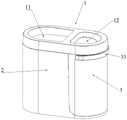
Referring to fig. 1-5, a dry and wet garbage can is used for collecting household garbage and solves the technical problems that peculiar smell is easily generated when dry and wet garbage is stored in a mixed mode in household garbage treatment, and messy placement is caused when a plurality of garbage cans collect the dry and wet garbage respectively. The dry and wet dual-purpose garbage can comprises a connecting piece 1, a dry can body 2 and a wet can body 3. The connecting piece 1 is used for detachably connecting the dry barrel body 2 and the wet barrel body 3 together, and can adopt common connecting pieces such as a buckle structure, a magnetic piece and the like, and the connecting piece 1 adopts a structure formed by a hoop 13 and a limiting ring 14 in the embodiment. The dry barrel body 2 is used for storing dry garbage, and the wet barrel body 3 is used for storing wet garbage; the dry barrel body 2 and the wet barrel body 3 can adopt plastic barrel bodies formed by injection molding. The connecting piece 1 is arranged on the dry barrel body 2 and/or the wet barrel body 3, and the dry barrel body 2 and the wet barrel body 3 are fixed together. Dry wet dual-purpose garbage bin sets up independent dry staving and wet staving, and dry staving 2 can be dismantled fixedly together with wet staving 3 for the garbage bin forms the overall structure that can deposit dry rubbish and wet rubbish respectively, avoids dry wet rubbish to deposit the peculiar smell that corrodes the volatile production together, also avoids the family to put respectively dry garbage bin and wet garbage bin and cause mixed and disorderly unordered, falls dry rubbish and wet rubbish respectively when still conveniently pouring rubbish. Set up connecting piece 1 in addition and further link together dry staving 2 and wet staving 3 for dry staving 2 is fixed more stable together with wet staving 3, avoids dry staving 2 and wet staving 3 to separate into independent structure and causes the family disordered and disorderly.
Referring to fig. 2-4, the dry barrel body 2 and the wet barrel body 3 are fixed together through a detachable structure, and can be fixed in the following way: the upper part of the wet barrel body 3 is provided with a hook 31, and the wet barrel body 3 is hung on the dry barrel body 2 through the hook 31, so that the dry barrel body 2 and the wet barrel body 3 are fixed together. One or more hooks 31 may be provided, and it is preferable that a plurality of hooks 31 are provided on the wet tub body 3, so that the wet tub body 3 is more stably fixed on the dry tub body 2. The embodiment shows that the structure provided with the three hooks 31 can make the wet barrel body 3 more stable to be fixed on the dry barrel body 2, improve the bearing capacity of the wet barrel body 3, and make the wet barrel body 3 capable of placing more and heavier wet garbage. The dry barrel body 2 is preferably provided with a gap matched with the hook 31, so that the hook 31 is just fixed at the opening part of the dry barrel body 2 and is not easy to displace to generate dislocation.
Referring to fig. 2 to 4, as a further preferred scheme, the upper bottom of the wet barrel body 3 is preferably further provided with an insert block 32, the dry barrel body 2 is provided with an insert hole 21, the dry barrel body 2 is integrally of an "L-shaped" structure, the insert hole 21 is arranged on a bottom plate of the dry barrel body 2 of the "L-shaped" structure, the insert block 32 is adapted to the insert hole 21, i.e., the size and the shape of the insert block 32 are consistent with those of the insert hole 21, so that the insert block 32 can be inserted into the insert hole 21. When the wet barrel body 3 and the dry barrel body 2 are installed, the hook 31 arranged on the wet barrel body 3 is hung on the opening edge of the dry barrel body 2, and meanwhile, the insert block 32 on the wet barrel body 3 is inserted into the insert hole 21 of the dry barrel body 2, so that the wet barrel body 3 is stably fixed on the dry barrel body 2. When the wet barrel body 3 needs to be taken down from the dry barrel body 2, the wet barrel body 3 is taken out by upwards drawing from the dry barrel body 2.
Referring to fig. 1 to 5, the connecting member 1 shown in the present embodiment includes a hoop 13 and a limiting ring 14, and the limiting ring 14 is adapted to the mouth of the dry barrel body 2 and/or the wet barrel body 3, that is, the size and the shape of the limiting ring 14 are consistent with the size and the shape of the inner side of the mouth of the dry barrel body 2 and/or the wet barrel body 3, so that the limiting ring 14 can be just inserted into the mouth of the dry barrel body 2 and/or the wet barrel body 3. Only one limiting ring 14 can be arranged and inserted into the mouth of the dry barrel body 2 or the wet barrel body 3; the two limiting rings 14 are preferably arranged, and the two limiting rings 14 are respectively inserted into the mouths of the dry barrel body 2 and the wet barrel body 3, so that the dry barrel body 2 and the wet barrel body 3 are better fixed together with the hoop 13, and the dry barrel body 2 and the wet barrel body 3 are prevented from being separated. In the embodiment shown, a stop collar 14 is provided inside the barrel body 2. The limiting ring 14 is arranged on the inner side of the hoop 13, the hoop 13 hoops the periphery of the dry barrel body 2 and the wet barrel body 3, the limiting ring 14 can be clamped on the inner side of a barrel opening of the dry barrel body 2 and/or the wet barrel body 3 when the dry barrel body and/or the wet barrel body are used, and the dry barrel body 2 and the wet barrel body 3 are hooped together through the hoop 13 to form an integral structure. The connecting piece 1 is provided with a dry garbage inlet 11 and a wet garbage inlet 12, the dry garbage inlet 11 is communicated into the dry barrel body 2, and the wet garbage inlet 12 is communicated into the wet barrel body 3, so that dry garbage and wet garbage can be conveniently and respectively put in.
Referring to fig. 1, 2 and 4, as a further preferred scheme, a handle 33 is provided on the wet barrel 3, and the wet barrel 3 is conveniently drawn upwards from the dry barrel 2 through the handle 33, so as to dump the garbage in the wet barrel 3. The handle 33 is preferably rotatably disposed on the wet bucket body 3 through a pair of rotating shafts, so that the handle 33 can be conveniently opened from the wet bucket body 3 for use and folded when not in use. The wet barrel body 3 is provided with the step structure 34, the step structure 34 is matched with the handle 33, namely, the width and the height of the step structure 34 are consistent with those of the handle 33, so that the handle 33 can be just folded on the step structure 34 when the handle 33 is not used, the wet barrel body 3 is enabled to be a structure with a smooth appearance, and the wet barrel body is not easy to pollute and convenient to clean.
Referring to fig. 3 and 4, as a further preferred scheme, it is preferable that a vertical limiting protrusion is disposed on the wet barrel body 3, and a vertical limiting groove is disposed on the dry barrel body 2, and the size and the shape of the limiting protrusion are the same as those of the limiting groove, so that when the dry barrel body 2 and the wet barrel body 3 are mounted together, the positioning can be performed through the limiting protrusion and the limiting groove, and the accurate alignment mounting of the dry barrel body and the wet barrel body is ensured.
Referring to fig. 1 to 5, when the dry and wet dual-purpose trash can of this embodiment is used, the wet can body 3 is installed in the opening edge of the dry can body 2 and the insertion hole 21 through the hook 31 and the insertion block 32, the limit ring 14 of the connecting member 1 is inserted into the opening of the dry can body 2, and the hoop 13 is hooped on the dry can body 2 and the wet can body 3 to hoop the dry can body 2 and the wet can body 3 together. When in use, dry garbage and wet garbage are respectively poured into the dry barrel body 2 and the wet barrel body 3. When the dry and wet garbage can is filled with garbage and needs to be dumped, the handle 33 can be used for pulling the wet can body 3 upwards from the dry can body 2 to dump the wet garbage, and then the dry garbage in the dry can body 2 is dumped.
Example two
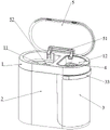
Referring to fig. 1 to 8, the overall structure of the dry and wet dual-purpose trash can in the embodiment is the same as that in the first embodiment, and includes a connecting member 1, a dry can body 2, and a wet can body 3. The connecting piece 1 is used for detachably connecting the dry barrel body 2 and the wet barrel body 3 together, and can adopt common connecting pieces such as a buckle structure, a magnetic piece and the like, and the connecting piece 1 adopts a structure formed by a hoop 13 and a limiting ring 14 in the embodiment. The dry barrel body 2 is used for storing dry garbage, and the wet barrel body 3 is used for storing wet garbage; the dry barrel body 2 and the wet barrel body 3 can adopt plastic barrel bodies formed by injection molding. The connecting piece 1 is arranged on the dry barrel body 2 and/or the wet barrel body 3, and the dry barrel body 2 and the wet barrel body 3 are fixed together. In addition, the wet dual-purpose garbage bin futilely of this embodiment still includes filter sieve 4, filter sieve 4 is installed on connecting piece 1 to the setting is in the opening top of wet staving 3, thereby when pouring wet rubbish such as tea into wet staving 3, solid waste can be stayed on filter sieve 4, and liquid waste can flow into in the wet staving 3 of below, realizes solid-liquid separation from this, and further better realization garbage separation makes things convenient for the rubbish clearance, avoids rubbish corruption fermentation to produce the peculiar smell.
Referring to fig. 7 and 8, the filter screen 4 of the present embodiment includes a screen 41 and a screen frame 42, the screen frame 42 is a frame structure, the screen 41 is fixed at the bottom of the screen frame 42, and the screen frame 42 can be supported on the connecting member 1, so that the solid waste in the wet waste is received above the wet bin 3, and the solid-liquid separation of the wet waste is realized. The screen 41 and the screen frame 42 may be formed as a single body, for example, as a single injection-molded plastic structure or a stamped and formed metal structure.
Referring to fig. 7 and 8, it is preferable that the wet tub 3 is provided with a positioning protrusion, and the filter sieve 4 is correspondingly provided with a positioning groove, so that the filter sieve 4 is positioned by the positioning protrusion and the positioning groove when the filter sieve 4 is installed on the wet tub 3, thereby realizing accurate installation of the filter sieve 4 and the wet tub 3. In addition, a handle for holding is preferably arranged on the filter sieve 4, so that the filter sieve 4 can be conveniently mounted on or taken down from the wet barrel body 3, the liquid garbage in the wet barrel body 3 and the solid garbage filtered by the filter sieve 4 can be conveniently poured, and the filter sieve 4 can be conveniently cleaned.
Referring to fig. 1 to 8, when the dry and wet dual-purpose trash can is used, the filter sieve 4 is installed on the wet can body 3, the wet can body 3 is installed in the opening edge and the insertion hole 21 of the dry can body 2 through the hook 31 and the insertion block 32, the limit ring 14 of the connecting piece 1 is inserted into the opening of the dry can body 2, and the hoop 13 is hooped on the dry can body 2 and the wet can body 3 to hoop the dry can body and the wet can body together. When the garbage can is used, dry garbage and wet garbage are respectively poured into the dry can body 2 and the wet can body 3, the wet garbage is filtered on the filter screen 4, the solid garbage is left on the filter screen 4, and the liquid garbage flows into the wet can body 3, so that the solid garbage and the liquid garbage can be prevented from being poured into the wet can body 3 together to be fermented to generate peculiar smell. When the dry and wet garbage can is filled with garbage and then needs to be dumped, the handle 33 can be used for pulling the wet can body 3 upwards from the dry can body 2 to dump the wet garbage, the solid garbage on the filter sieve 4 and the liquid garbage in the wet can body 3 are respectively dumped, the filter sieve 4 is firstly taken out to dump the solid garbage on the filter sieve 4, and then the dry garbage in the dry can body 2 is dumped. The dry garbage is taken out from the wet barrel body 3 and then poured out through the dry barrel body 2.
EXAMPLE III
Referring to fig. 1 to 9, the overall structure of the dry and wet dual-purpose trash can of the present embodiment is the same as that of the dry and wet dual-purpose trash can of the second embodiment, and includes a connecting member 1, a dry can body 2, a wet can body 3, and a filter sieve 4. The connecting member 1 is used for detachably connecting the dry barrel body 2 and the wet barrel body 3 together, and may adopt a fastening structure, a magnetic part and other common connecting members, and in this embodiment, the connecting member 1 adopts a structure formed by a hoop 13 and a limit ring 14. The dry barrel body 2 is used for storing dry garbage, and the wet barrel body 3 is used for storing wet garbage; the dry barrel body 2 and the wet barrel body 3 can adopt plastic barrel bodies formed by injection molding. The connecting piece 1 is arranged on the dry barrel body 2 and/or the wet barrel body 3, and the dry barrel body 2 and the wet barrel body 3 are fixed together. The filter sieve 4 is installed on connecting piece 1 to the setting is in the opening top of wet staving 3, thereby when pouring wet rubbish such as tea to wet staving 3, solid refuse can be stayed on the filter sieve 4, and liquid refuse can flow into in the wet staving 3 of below, realizes solid-liquid separation from this, further better realization rubbish separation, makes things convenient for the rubbish clearance, avoids rubbish corruption fermentation to produce the peculiar smell. In addition, the connecting piece 1 of the dry and wet dual-purpose garbage can in the embodiment is provided with the can cover 5, and the can cover 5 can be opened and closed on the dry garbage inlet 11 and the wet garbage inlet 12, so that the can cover 5 can be covered when garbage is not thrown, and the phenomenon that the surrounding environment is influenced by the overflow of peculiar smell generated by the garbage in the dry can body 2 and the wet can body 3 is avoided; when throwing garbage, the barrel cover 5 can be opened to throw the garbage into the dry barrel body 2 and the wet barrel body 3.
Referring to fig. 9, the tub cover 5 of the present embodiment is mounted on one side of the connection member 1 by a rotation member 51; the other side of the connector 1 is provided with a switch 52, so that the barrel cover 5 arranged on the connector 1 can be opened and closed through the switch 52. The rotating member 51 may adopt a common rotating structure such as a hinge; the switch 52 may be a conventional switch structure, and preferably an electric switch, such as an infrared trigger switch, which can be linked with the rotating member 51, so that the lid 5 is automatically opened by the trigger switch 52, and the garbage can is more convenient to use.
When the dry and wet dual-purpose garbage can is used, the can cover 5 is opened through the switch 52 to pour garbage into the dry can body 2 and the wet can body 3, and the can cover 5 is covered on the dry can body 2 and the wet can body 3 when the garbage is not thrown away. When the garbage in the garbage can needs to be cleaned, the connecting piece 1 is taken out, and the wet can body 3 is extracted from the dry can body 2 to respectively pour the dry garbage and the wet garbage.
It is obvious that the above embodiments of the present invention are only examples for clearly illustrating the present invention, and are not limitations to the embodiments of the present invention. Other variations and modifications will be apparent to persons skilled in the art in light of the above description. And are neither required nor exhaustive of all embodiments. Any modification, equivalent replacement or improvement made within the spirit and principle of the present invention should be included in the protection scope of the claims of the present invention.
Claims (10)
1. The utility model provides a wet or dry garbage bin which characterized in that: the barrel comprises a connecting piece (1), a dry barrel body (2) and a wet barrel body (3), wherein the dry barrel body (2) and the wet barrel body (3) are detachably fixed with each other, and the connecting piece (1) is arranged on the dry barrel body (2) and the wet barrel body (3) to fix the dry barrel body (2) and the wet barrel body (3) together; the garbage can is characterized in that a dry garbage inlet (11) and a wet garbage inlet (12) are formed in the connecting piece (1), the dry garbage inlet (11) is communicated into the dry can body (2), and the wet garbage inlet (12) is communicated into the wet can body (3).
2. The dry and wet trash can of claim 1, wherein: the wet barrel body (3) is provided with a hook (31), and the wet barrel body (3) is hung on the dry barrel body (2) through the hook (31).
3. The dry and wet trash can of claim 2, wherein: the wet barrel body (3) is further provided with an inserting block (32), the dry barrel body (2) is provided with an inserting hole (21), the inserting block (32) is matched with the inserting hole (21), and the inserting block (32) is inserted into the inserting hole (21).
4. The dry and wet trash can of claim 3, wherein: a handle (33) is arranged on the wet barrel body (3).
5. The dry and wet trash can of claim 4, wherein: the lifting handle (33) is rotatably arranged on the wet barrel body (3); the wet barrel body (3) is provided with a step structure (34), the step structure (34) is matched with the handle (33), and the handle (33) can be folded on the step structure (34).
6. The dry and wet trash can as claimed in any one of claims 1 to 5, wherein: the connecting piece (1) comprises a hoop (13) and a limiting ring (14), the limiting ring (14) is arranged on the inner side of the hoop (13), and the hoop (13) is hooped on the periphery of the dry barrel body (2) and the wet barrel body (3); the limiting ring (14) is matched with the opening of the dry barrel body (2) and/or the wet barrel body (3) and can be inserted into the opening of the dry barrel body (2) and/or the wet barrel body (3).
7. The dry and wet trash can of claim 6, wherein: still include filter sieve (4), filter sieve (4) are installed on connecting piece (1) to the setting is above the opening of wet staving (3).
8. The dry and wet trash can of claim 7, wherein: the filter screen (4) comprises a screen mesh (41) and a screen frame (42), wherein the screen mesh (41) is fixed at the bottom of the screen frame (42), and the screen frame (42) can be supported on the connecting piece (1).
9. The dry and wet trash can of claim 8, wherein: the connecting piece (1) is provided with a barrel cover (5), and the barrel cover (5) can be opened and closed to be arranged on the dry garbage inlet (11) and the wet garbage inlet (12).
10. The dry and wet trash can of claim 9, wherein: the barrel cover (5) is arranged on one side of the connecting piece (1) through a rotating piece (51); and a switch (52) is arranged on the other side of the connecting piece (1).
Priority Applications (1)
| Application Number | Priority Date | Filing Date | Title |
|---|---|---|---|
| CN202220055653.XU CN216835438U (en) | 2022-01-10 | 2022-01-10 | Dry-wet dual-purpose garbage can |
Applications Claiming Priority (1)
| Application Number | Priority Date | Filing Date | Title |
|---|---|---|---|
| CN202220055653.XU CN216835438U (en) | 2022-01-10 | 2022-01-10 | Dry-wet dual-purpose garbage can |
Publications (1)
| Publication Number | Publication Date |
|---|---|
| CN216835438U true CN216835438U (en) | 2022-06-28 |
Family
ID=82113649
Family Applications (1)
| Application Number | Title | Priority Date | Filing Date |
|---|---|---|---|
| CN202220055653.XU Active CN216835438U (en) | 2022-01-10 | 2022-01-10 | Dry-wet dual-purpose garbage can |
Country Status (1)
| Country | Link |
|---|---|
| CN (1) | CN216835438U (en) |
-
2022
- 2022-01-10 CN CN202220055653.XU patent/CN216835438U/en active Active
Similar Documents
| Publication | Publication Date | Title |
|---|---|---|
| CN208683601U (en) | A kind of municipal works separation of solid and liquid environment-friendly trash can | |
| CN216835438U (en) | Dry-wet dual-purpose garbage can | |
| CN207759452U (en) | A kind of dustbin for kitchen use | |
| CN208165797U (en) | A kind of environment-friendly trash can of separation of solid and liquid | |
| CN208453686U (en) | A kind of environment-friendly trash can that layering is collected | |
| CN211544723U (en) | Solid-liquid separation has environmental protection garbage bin of removing peculiar smell function | |
| CN112265765A (en) | Special classification garbage bin in kitchen | |
| CN210683628U (en) | Compost bucket with inner container | |
| CN211618865U (en) | Garbage recycling bin convenient to clean | |
| CN217457291U (en) | Odor-removing classification garbage can | |
| CN214166106U (en) | Can carry out automatic classification's dustbin in park | |
| CN219044611U (en) | Plastic dustbin with solid-liquid separation structure | |
| CN213567825U (en) | Environment-friendly garbage can | |
| CN217295788U (en) | Combined garbage can | |
| CN207759445U (en) | A kind of garbage sorter | |
| CN209905623U (en) | Domestic garbage bin of convenient clearance | |
| CN202098766U (en) | Novel garbage bin | |
| CN209258864U (en) | Cabinet door suspension-type garbage bin | |
| CN211618825U (en) | Garbage can capable of filtering liquid | |
| CN214932734U (en) | Novel garbage can | |
| CN209815982U (en) | Domestic waste classification device | |
| CN217295819U (en) | Garbage can | |
| CN216271241U (en) | Environment-friendly dustbin | |
| CN220222145U (en) | Special garbage bin of tea-drinking with tea separation function | |
| CN216637659U (en) | Gastroenterology is partial shipment garbage bin for clinical care |
Legal Events
| Date | Code | Title | Description |
|---|---|---|---|
| GR01 | Patent grant | ||
| GR01 | Patent grant |