CN216831341U - Novel punching die - Google Patents
Novel punching die Download PDFInfo
- Publication number
- CN216831341U CN216831341U CN202220582842.2U CN202220582842U CN216831341U CN 216831341 U CN216831341 U CN 216831341U CN 202220582842 U CN202220582842 U CN 202220582842U CN 216831341 U CN216831341 U CN 216831341U
- Authority
- CN
- China
- Prior art keywords
- deformation
- fixedly connected
- upper die
- forming groove
- die base
- Prior art date
- Legal status (The legal status is an assumption and is not a legal conclusion. Google has not performed a legal analysis and makes no representation as to the accuracy of the status listed.)
- Active
Links
Images


Landscapes
- Perforating, Stamping-Out Or Severing By Means Other Than Cutting (AREA)
Abstract
The utility model discloses a novel punching die, which comprises an upper fixed block, an upper die base, a lower template, a male punch, a forming groove and a deformation groove; the top of the upper fixing block is fixedly connected with a driving device, and the bottom of the upper fixing block is fixedly connected with the upper die base; the lower die base is arranged right below the upper die base, and the top surface of the lower die base is fixedly connected with the lower template; the bottom surface of the upper die holder is fixedly connected with the male punch, the upper surface of the lower template is provided with a forming groove matched with the male punch, the periphery of the forming groove is surrounded by a deformation groove in the upper surface of the lower template, and the inner surface of the deformation groove forms a buffering deformation surface; an included angle is formed between the side wall of the buffering deformation surface, which is close to the forming groove, and the side wall of the forming groove. Utilize the utility model discloses it is die-cut to carry out the card, can effectively prevent the deformation of the die-cut in-process of card for die-cut effect is better, and the qualification rate of certificate is higher.
Description
Technical Field
The utility model relates to a card preparation technical field, concretely relates to novel die-cut mould for card preparation.
Background
For the manufacture of the certificate card, various domestic manufacturers carry out related process research, and the domestic manufacturers mainly adopt an inner layer PET and outer layer PETG mode, so that the certificate card is not wear-resistant and has short service cycle. Traditional card punching process is all through die-cut mould direct die-cut, and little deformation can appear in the card forming process, wholly does not influence the pleasing to the eye and the result of use of card, but along with the internet is more and more flourishing, the card has covered a large amount of chips and response circuit, and little deformation in the card punching process can lead to the inside phenomenon that damages appears of card.
SUMMERY OF THE UTILITY MODEL
Not enough to prior art, the utility model aims at providing a novel die-cut mould.
In order to achieve the above purpose, the utility model adopts the following technical scheme:
a novel punching die comprises an upper fixing block, an upper die base, a lower die plate, male punches, a forming groove and a deformation groove;
the top of the upper fixing block is fixedly connected with a driving device, and the bottom of the upper fixing block is fixedly connected with the upper die base;
the lower die base is arranged right below the upper die base, and the top surface of the lower die base is fixedly connected with the lower template;
the bottom surface of the upper die holder is fixedly connected with the male punch, and the upper surface of the lower template is provided with a forming groove matched with the male punch;
forming deformation grooves around the forming grooves on the upper surface of the lower template, wherein buffer deformation surfaces are formed on the inner surfaces of the deformation grooves; an included angle is formed between the side wall of the buffering deformation surface, which is close to the forming groove, and the side wall of the forming groove.
Further, the included angle between the tangent line of the side wall of the buffer deformation surface close to the forming groove and the tangent line of the side wall of the forming groove is 30 degrees.
Furthermore, a stripping device is arranged on the outer side of the male punch and used for being matched with the male punch to drive the punched waste to be separated from the male punch.
Furthermore, the stripping device comprises a stripping plate which is arranged on the outer side of the male punch and can move along the height direction of the male punch, the top of the stripping plate is fixedly connected with a limiting column, and the upper end of the limiting column can penetrate through the upper die holder in a vertically movable manner; one end of the limiting column penetrating through the upper surface of the upper die holder is provided with a limiting part; a first reset spring is arranged between the stripper plate and the upper die base.
Furthermore, a resetting device for driving the upper die holder to return to the initial position is arranged between the upper die holder and the lower die holder.
Furthermore, the reset device comprises a first guide column and a second guide column, the upper ends of the first guide column and the second guide column respectively penetrate through the two sides of the upper die base in a vertically movable manner, and the lower ends of the first guide column and the second guide column are respectively fixedly connected to the two sides of the lower die base; the outer side wall of the first guide post is sleeved with a second reset spring, and the second reset spring is located between the upper die base and the lower die base.
The beneficial effects of the utility model reside in that: utilize the utility model discloses it is die-cut to carry out the card, can effectively prevent the deformation of the die-cut in-process of card for die-cut effect is better, and the qualification rate of certificate is higher.
Drawings
Fig. 1 is a schematic view of a mold structure in an embodiment of the present invention;
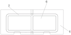
fig. 2 is a schematic structural view of a lower template in the embodiment of the present invention;
fig. 3 is a schematic view of an included angle between the buffer deformation surface and the forming groove in the embodiment of the present invention.
Detailed Description
The present invention will be further described with reference to the accompanying drawings, and it should be noted that the present embodiment is based on the technical solution, and the detailed embodiments and the specific operation processes are provided, but the protection scope of the present invention is not limited to the present embodiment.
The embodiment provides a novel punching die, as shown in fig. 1-2, which includes an upper fixing block 1, an upper die base 2, a lower die base 3, a lower die plate 4, a male punch 5, a forming groove 6, and a deformation groove 7;
the top of the upper fixing block 1 is fixedly connected with a driving device (which can be a hydraulic cylinder or a pneumatic cylinder, not shown in the figure), and the bottom of the upper fixing block 1 is fixedly connected with the upper die holder 2. In this embodiment, the upper die holder 2 is fixedly connected to the upper fixing block 1 by screws.
The lower die holder 3 is arranged right below the upper die holder 2, and the top surface of the lower die holder 3 is fixedly connected with the lower template 4. In this embodiment, the lower template 4 is fixedly connected with the lower die holder 3 through screws.
The bottom surface of the upper die holder 2 is fixedly connected with the male punch 5, the upper surface of the lower template 4 is provided with a forming groove 6 matched with the male punch 5, the periphery of the forming groove 6 is provided with a deformation groove 7 on the upper surface of the lower template 4, and the inner surface of the deformation groove 7 forms a buffer deformation surface;
in the present embodiment, as shown in fig. 3, the side wall of the buffer deformation surface close to the forming groove 6 forms an included angle with the side wall of the forming groove 6. The forming included angle between the buffering deformation surface and the forming groove is made, so that a knife edge is formed between the buffering deformation surface and the forming groove, the punching process is assisted to be rapidly and accurately realized, the deformation force generated by punching is dispersed to waste materials outside the forming groove range, and the deformation generated in the punching process of the card is reduced. More specifically, in the present embodiment, the included angle between the tangent of the buffer deformation surface near the side wall of the forming groove 6 and the tangent of the side wall of the forming groove 6 is 30 °. Through tests, the included angle of 30 degrees is suitable, the sharpness of the knife edge is not enough due to too large included angle, and the service life of the knife edge is shortened due to too small included angle.
In this embodiment, the outer side of the male punch 5 is provided with a stripping device, and the stripping device is used for cooperating with the male punch 5 to drive the punched waste material to be separated from the male punch 5. The stripper device comprises a stripper plate 8 which is arranged on the outer side of the male punch 5 and can move along the height direction of the male punch 5, the top of the stripper plate 8 is fixedly connected with a limiting column 9, and the upper end of the limiting column 9 can penetrate through the upper die holder 2 in a vertically movable manner; and a limiting part 10 is arranged at one end of the limiting column 9 penetrating through the upper surface of the upper die holder 2. In the present embodiment, a first return spring 11 is provided between the stripper plate 8 and the upper die base 2.
In this embodiment, a resetting device for driving the upper die holder 2 to return to the initial position is disposed between the upper die holder 2 and the lower die holder 3. Specifically, the resetting device comprises a first guide column 12 and a second guide column 13, the upper ends of the first guide column 12 and the second guide column 13 respectively penetrate through two sides of the upper die holder 2 in a vertically movable manner, and the lower ends of the first guide column 12 and the second guide column 13 are respectively fixedly connected to two sides of the lower die holder 3; the outer side wall of the first guide column 12 is sleeved with a second return spring 14, and the second return spring 14 is located between the upper die holder 2 and the lower die holder 3.
It should be noted that the mold of this embodiment is a two-end mold, as shown in fig. 2, has two forming grooves, and can be used for punching eight-card-type certificates such as identification cards, that is, 2 × 8 typeset certificates. The three-head die or more three-head dies can be arranged according to the actual production requirements, for example, three forming grooves and matched male punches are arranged for the three-head die, and the three-head die can be used for punching 3-8 typeset certificates.
The working principle of the novel punching die is as follows:
during operation, place the card material on lower bolster 4, drive through drive arrangement and go up fixed block 1 and descend to drive upper die base 2 and move and compress second reset spring 14 to lower die base 3, go up fixed block 1 and descend the in-process, take off flitch 8 and the card material butt that the upper surface of lower bolster 4 is located outside the shaping groove 6 scope, public punching 5 continues to descend, and first reset spring 11 is compressed under the reaction force of lower bolster 4 this moment. The punch 5 cuts the card material, and the cut card falls into the forming groove 6.
After the cutting is finished, in the upward process of the male punch 5, the stripper plate 8 is continuously abutted to the waste material of the identification card material outside the range of the forming groove 6 on the lower template 4 under the action of the first return spring 11, the waste material is prevented from going upward along with the male punch 5, and after the male punch 5 is completely separated from the forming groove 6, the stripper plate 8 goes upward along with the upper die base 2 to return to the initial position under the action of the second return spring 14 and the driving device. Wherein, the spacing post 9 plays the guide effect to the motion of taking off flitch 8, and spacing portion 10 guarantees that the upper end of spacing post 9 can not break away from upper die base 2. The first guide post 12 and the second guide post 13 guide the movement of the upper die holder 2.
Various corresponding changes and modifications can be made by those skilled in the art according to the above technical solutions and concepts, and all such changes and modifications should be included in the protection scope of the present invention.
Claims (6)
1. A novel punching die is characterized by comprising an upper fixing block, an upper die holder, a lower template, a male punch, a forming groove and a deformation groove;
the top of the upper fixing block is fixedly connected with a driving device, and the bottom of the upper fixing block is fixedly connected with the upper die base;
the lower die base is arranged right below the upper die base, and the top surface of the lower die base is fixedly connected with the lower template;
the bottom surface of the upper die holder is fixedly connected with the male punch, and the upper surface of the lower template is provided with a forming groove matched with the male punch;
forming deformation grooves around the forming grooves on the upper surface of the lower template, wherein buffer deformation surfaces are formed on the inner surfaces of the deformation grooves; an included angle is formed between the side wall of the buffering deformation surface, which is close to the forming groove, and the side wall of the forming groove.
2. The novel punching die as claimed in claim 1, wherein the included angle between the tangent line of the buffer deformation surface close to the side wall of the forming groove and the tangent line of the side wall of the forming groove is 30 °.
3. A novel punching die according to claim 1, characterized in that a stripping device is arranged on the outer side of the male punch and is used for cooperating with the male punch to drive the punched waste material to be separated from the male punch.
4. The novel punching die as claimed in claim 3, wherein the stripping device comprises a stripping plate which is arranged on the outer side of the male punch and can move along the height direction of the male punch, the top of the stripping plate is fixedly connected with a limiting column, and the upper end of the limiting column can penetrate through the upper die holder in a vertically movable manner; one end of the limiting column penetrating through the upper surface of the upper die holder is provided with a limiting part; a first reset spring is arranged between the stripper plate and the upper die base.
5. The novel punching die as claimed in claim 1, wherein a resetting device for driving the upper die holder to return to an initial position is arranged between the upper die holder and the lower die holder.
6. The novel punching die as claimed in claim 5, wherein the resetting device comprises a first guide column and a second guide column, the upper ends of the first guide column and the second guide column respectively penetrate through two sides of the upper die base in a vertically movable manner, and the lower ends of the first guide column and the second guide column are respectively fixedly connected to two sides of the lower die base; the outer side wall of the first guide post is sleeved with a second reset spring, and the second reset spring is located between the upper die base and the lower die base.
Priority Applications (1)
| Application Number | Priority Date | Filing Date | Title |
|---|---|---|---|
| CN202220582842.2U CN216831341U (en) | 2022-03-17 | 2022-03-17 | Novel punching die |
Applications Claiming Priority (1)
| Application Number | Priority Date | Filing Date | Title |
|---|---|---|---|
| CN202220582842.2U CN216831341U (en) | 2022-03-17 | 2022-03-17 | Novel punching die |
Publications (1)
| Publication Number | Publication Date |
|---|---|
| CN216831341U true CN216831341U (en) | 2022-06-28 |
Family
ID=82097378
Family Applications (1)
| Application Number | Title | Priority Date | Filing Date |
|---|---|---|---|
| CN202220582842.2U Active CN216831341U (en) | 2022-03-17 | 2022-03-17 | Novel punching die |
Country Status (1)
| Country | Link |
|---|---|
| CN (1) | CN216831341U (en) |
Cited By (1)
| Publication number | Priority date | Publication date | Assignee | Title |
|---|---|---|---|---|
| CN114750243A (en) * | 2022-03-17 | 2022-07-15 | 公安部第一研究所 | Novel punching die |
-
2022
- 2022-03-17 CN CN202220582842.2U patent/CN216831341U/en active Active
Cited By (1)
| Publication number | Priority date | Publication date | Assignee | Title |
|---|---|---|---|---|
| CN114750243A (en) * | 2022-03-17 | 2022-07-15 | 公安部第一研究所 | Novel punching die |
Similar Documents
| Publication | Publication Date | Title |
|---|---|---|
| CN208976601U (en) | A kind of stamping die for reversely cutting off structure with double-slider | |
| CN205869225U (en) | Crooked blanking die | |
| CN216831341U (en) | Novel punching die | |
| CN212285529U (en) | Workpiece shearing, punching and bending compound die | |
| CN202516925U (en) | Cutting and punching die | |
| CN214919840U (en) | Angle brace plate forming die | |
| CN204892703U (en) | A stamping die that is used for modulus of continuity to cut edge and 90 degrees synchronous completions of bending | |
| CN206981513U (en) | A kind of double-deck blanking equipment for producing circular steel plate | |
| CN104525683A (en) | Thin workpiece compression blanking die | |
| CN213826723U (en) | Fixing device for producing motor iron core punching machine | |
| CN114750243A (en) | Novel punching die | |
| CN215965883U (en) | Stamping die for producing aluminum foil lunch box | |
| CN211360323U (en) | Trimming and punching forming die | |
| CN210847981U (en) | Composite die for cutting, bending and one-step forming | |
| CN210253821U (en) | Continuous stamping die of power pack | |
| CN207914393U (en) | A kind of fine blanking die of punch-die and cavity plate | |
| CN214442344U (en) | Floating mechanism of automobile stamping die | |
| CN214977129U (en) | Be applied to mechanism that punctures of thin pin of accurate type | |
| CN216027556U (en) | Swinging stamping die for negative angle shaping | |
| CN216989501U (en) | Punching tool for continuous die | |
| CN220052024U (en) | Negative pressure feeding and positioning structure for diaphragm punching die | |
| CN219703231U (en) | Continuous stamping die of secondary drawing | |
| CN210651029U (en) | Punching device for belt body of woven outer waistband | |
| CN214349068U (en) | Stamping and cutting die for alloy resistor | |
| CN221620511U (en) | Copper punching mechanism |
Legal Events
| Date | Code | Title | Description |
|---|---|---|---|
| GR01 | Patent grant | ||
| GR01 | Patent grant |