CN216828236U - Rotary traceless bending die for mounting bracket of electric drive rear axle motor of automobile - Google Patents
Rotary traceless bending die for mounting bracket of electric drive rear axle motor of automobile Download PDFInfo
- Publication number
- CN216828236U CN216828236U CN202123107111.7U CN202123107111U CN216828236U CN 216828236 U CN216828236 U CN 216828236U CN 202123107111 U CN202123107111 U CN 202123107111U CN 216828236 U CN216828236 U CN 216828236U
- Authority
- CN
- China
- Prior art keywords
- bending
- die
- plate
- lower die
- rotary
- Prior art date
- Legal status (The legal status is an assumption and is not a legal conclusion. Google has not performed a legal analysis and makes no representation as to the accuracy of the status listed.)
- Active
Links
Images


Abstract
The utility model relates to a rotary traceless bending die for a motor mounting bracket of an electrically driven rear axle of an automobile, which comprises an upper die structure and a lower die structure, wherein the upper die structure comprises an upper die plate, a guide sleeve, an upper fixing plate and a bending upper die; the lower die structure comprises a guide pillar, a first rotary bending lower die, a positioning pin, a lower fixing plate, a bending lower die backing plate, a bending lower die supporting plate, a second rotary bending lower die, a lower backing plate, a lower die plate, an ejector rod, a rotating shaft guide plate, a rotating shaft and a rotating shaft pressing plate. This mould optimizes into a process traditional three processes (being prebending, plastic bending, artifical polishing), and production efficiency has improved 3.2 times to the mould development cost of a set of process has been practiced thrift, but the lower mould of mould adopts rotatable structure to increase crooked lower mould backup plate and crooked lower mould layer board isotructure, make the mould life-span improve 1.5 times, and adopt the curved technology of rotation type no trace, improved product quality (being the product is crooked no indentation), thereby reduced manufacturing cost.
Description
Technical Field
The utility model belongs to the technical field of mechanical die structure and specifically relates to a no trace bending die of car electric drive rear axle motor installing support rotation type is related to.
Background
The electrically driven rear axle for car is composed of drive axle body, drive motor and speed reducer fixed to drive axle body, and motor installing frame for fixing drive motor to drive axle body and with motor shaft connected to input gear in vertical casing.
According to the requirement of stamping and bending manufacturability, when the plate thickness is less than or equal to 6.0mm, the minimum bending radius is generally 1t, and when the plate thickness is more than 6.0mm, the minimum bending radius is generally 1.25 t-1.5 t (t is the plate thickness), and the bending radius of the motor mounting bracket is smaller than the minimum bending radius required by the plate, namely, the plate thickness is smaller than 1.25 times (the product bending radius is R5, the workpiece plate thickness is 8.0mm, and the material is B510L);
for example, chinese patent application No. 201910450091.1 discloses a bending and embossing mold, which includes an upper mold assembly, a lower mold assembly and a lever assembly. The upper die assembly comprises a bending male die, and a convex pressing groove is formed in the bending male die. The lower die assembly comprises a first die core and a second die core, the two first die cores are symmetrically arranged on two sides of the second die core, the first die core and the second die core can be spliced to form a bending female die, and a protruding boss matched with the protruding groove is arranged on the second die core. The lever assembly comprises a lever, one end of the lever can be connected with the upper die assembly, and the other end of the lever is connected with the two first die cores.
According to the related technology, when the bending and embossing die is used for processing products, the die can only be pre-bent by using a large arc and then is shaped and bent by using a small arc, but the product is bent for the second time, so that the bending indentation is difficult to avoid, the strength of the product is influenced, the quality of the product has risks, and the crack and the bending indentation at two side ends are increased by manually polishing.
The utility model discloses just based on the optimizability that production technology exists among the prior art and considering, design rotation type no trace bending die, optimize three processes (crooked and artifical polishing in advance promptly) for one process, the crooked back of product does not have the indentation moreover, can satisfy production car electric drive rear axle motor installing support rotation type no trace bending die through designing one kind like this, improves product quality and production efficiency, just seems very necessary.
SUMMERY OF THE UTILITY MODEL
The utility model aims at providing a no trace bending die of car electric drive rear axle motor installing support rotation type through the lower mould design rotatable formula of will bending to increase crooked lower mould backup plate and crooked lower bolster isotructure and improve mould life-span and product quality. The rotary traceless bending die is arranged on a hydraulic machine to carry out bending working procedure processing on a motor mounting bracket.
Realize the utility model discloses a technical scheme that the purpose was adopted as follows:
a rotary traceless bending die for a motor mounting bracket of an electrically driven rear axle of an automobile comprises an upper die structure and a lower die structure, wherein the upper die structure comprises an upper die plate, a guide sleeve, an upper fixing plate and a bending upper die;
the lower die structure comprises a guide pillar, a first rotary bending lower die, a positioning pin, a lower fixing plate, a bending lower die backing plate, a bending lower die supporting plate, a second rotary bending lower die, a lower backing plate, a lower die plate, an ejector rod, a rotating shaft guide plate, a rotating shaft and a rotating shaft pressing plate;
the bending upper die is assembled in a fixing groove of the upper fixing plate through interference fit and connected with the upper fixing plate through bolts from the upper end face of the bending upper die, the guide sleeves are assembled in guide sleeve holes on two sides of the upper die plate through interference fit, and the upper die plate is connected with the upper fixing plate through bolts and positioning pins;
the two bending lower die backup plates are arranged on the left side and the right side of a fixed cavity of the lower fixing plate in an interference fit way, and are respectively connected with the lower fixing plate through bolts from the side edges, the guide posts are arranged in guide post holes at the two sides of the lower template in an interference fit manner, the lower template and the lower backing plate are connected with the lower fixing plate through bolts and positioning pins, the three ejector rods are directly placed in the corresponding ejector rod holes of the lower backing plate and the lower template through clearance fit, the bending lower supporting plate is directly placed in a cavity formed by the lower fixing plate and the bending lower backing plate through clearance fit, the four positioning pins are respectively arranged in the corresponding positioning pin fixing holes of the first rotary bending lower die and the second rotary bending lower die in an interference fit manner, the small end parts of the two rotating shafts are respectively arranged in the rotating shaft holes corresponding to the two ends of the first rotary bending lower die and the second rotary bending lower die in an interference fit manner, the first rotary bending lower die and the second rotary bending lower die can freely rotate around rotating shafts at two ends;
the big end parts of the two rotating shafts are respectively placed in the rotating shaft guide grooves of the upper rotating shaft guide plate and the lower rotating shaft guide plate through clearance fit, the two rotating shaft guide plates are arranged on the upper edge and the lower edge of a fixing cavity formed by the lower fixing plate and the bent lower die backup plate through interference fit and are respectively connected with the lower die plate and the lower backing plate through bolts from the lower end face, and the two rotating shaft pressing plates are respectively connected with the rotating shaft guide plates through bolts from the side edges.
Furthermore, the two ends of the first rotary bending lower die and the second rotary bending lower die are respectively provided with a rotating shaft, the small end part of each rotating shaft is in interference fit with the first rotary bending lower die and the second rotary bending lower die, the large end part of each rotating shaft is in clearance fit with the rotating shaft guide groove of the rotating shaft guide plate, and the clearance between the two surfaces is 0.13-0.15 mm.
Furthermore, the lower die part is additionally provided with a lower bending die backup plate and a lower bending die supporting plate, so that the lower bending die backup plate and the lower bending die supporting plate are always supported in the whole bending process of the first rotary bending lower die and the second rotary bending lower die, and the die strength and the product quality are improved.
Furthermore, the left side and the right side of the bent lower die supporting plate are both provided with a guide boss, a guide groove is formed in the middle of the bent lower die backup plate, the guide boss of the bent lower die supporting plate is in clearance fit with the guide groove of the bent lower die backup plate, and the clearance between the two sides is 0.18-0.20 mm, so that the bent lower die supporting plate is prevented from moving, and the die strength and the product quality are improved.
The bending lower die backup plate of the lower die part is of an insert type, the lower fixing plate is of an integral type, the bending lower die backup plate is fixed in a cavity of the lower fixing plate through interference fit, when the die is adjusted, if the bending angle of a product is large, the thickness of the bending lower die backup plate can be thickened, if the bending angle of the product is small, the bending lower die backup plate can be thinned, maintained conveniently and quickly, the strength of the lower die can be improved, and the service life of the die is prolonged.
Furthermore, the lower end surfaces of the first rotary bending lower die and the second rotary bending lower die are both provided with an inclined surface, the upper end surface of the lower bending die backing plate is also provided with an inclined surface, when the die reaches a bottom dead center, the contact areas of the first rotary bending lower die and the second rotary bending lower die with the bending lower die supporting plate respectively are increased, and the contact areas of the lower bending die backing plate with the first rotary bending lower die and the second rotary bending lower die are increased, so that the die strength and the product quality are improved.
Furthermore, the double-sided clearance between the guide pillar and the guide sleeve is 0.16-0.18 mm.
The utility model has the advantages that: the small end part of a rotating shaft of the die structure is in interference fit with the first rotary bending lower die and the second rotary bending lower die, and the large end part of the rotating shaft is in clearance fit with a rotating shaft guide groove of a rotating shaft guide plate, so that one ends of the first rotary bending lower die and the second rotary bending lower die can smoothly and vertically move up and down along the rotating shaft guide groove of the rotating shaft guide plate, and the other ends of the first rotary bending lower die and the second rotary bending lower die can also rotate around the rotating shaft, so that a product is always in contact with the upper surfaces of the first rotary bending lower die and the second rotary bending lower die in the whole bending process of the die, and no indentation is generated in the bending process of the product;
in addition, the first rotary bending lower die and the second rotary bending lower die are always supported by a bending lower die backup plate and a bending lower die supporting plate in the whole bending process, so that the die strength and the product quality are improved;
this mould optimizes into a process traditional three processes (being prebending, plastic bending, artifical polishing), and production efficiency has improved 3.2 times to the mould development cost of a set of process has been practiced thrift, but the lower mould of mould adopts rotatable structure to increase crooked lower mould backup plate and crooked lower mould layer board isotructure, make the mould life-span improve 1.5 times, and adopt the curved technology of rotation type no trace, improved product quality (being the product is crooked no indentation), thereby reduced manufacturing cost.
Drawings
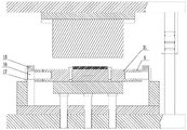
Fig. 1 is a schematic front view of the mold of the present invention;
FIG. 2 is a schematic top view of the lower mold structure of the present invention;
fig. 3 is a schematic diagram of the structure of the die in right view;
fig. 4 is a schematic view of the bottom dead center of the mold of the present invention;
fig. 5a is a schematic structural view of a first rotary bending lower die of the present invention;
fig. 5b is a schematic top view of a first rotary bending lower die of the inventive die;
fig. 6a is a schematic structural view of a second rotary bending lower die of the present invention;
fig. 6b is a schematic top view of a second rotary bending lower die of the present invention;
fig. 7 is a schematic view of a structure of a rotating shaft guide plate of the mold of the present invention;
FIG. 8 is a schematic structural view of a curved lower mold pallet of the mold of the present invention;
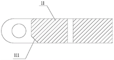
fig. 9 is a schematic structural view of the motor mounting bracket (workpiece) of the present invention.
Description of reference numerals: the device comprises an upper template 1, a guide sleeve 2, an upper fixing plate 3, a bending upper die 4, a guide pillar 5, a first rotary bending lower die 6, a first chamfer inclined surface 61, a positioning pin 7, a lower fixing plate 8, a bending lower die backing plate 9, a third chamfer inclined surface 91, a bending lower die supporting plate 10, a guide boss 101, a second rotary bending lower die 11, a second chamfer inclined surface 111, a lower backing plate 12, a lower die plate 13, an ejector rod 14, a rotating shaft guide plate 15, a rotating shaft guide groove 151, a rotating shaft 16, a rotating shaft pressing plate 17 and a workpiece 18.
Detailed Description
In order to make the objects, technical solutions and advantages of the present invention more clearly understood, the present invention is further described in detail below with reference to the accompanying drawings and embodiments. It should be understood that the specific embodiments described herein are for purposes of illustration only and are not intended to limit the invention.
As shown in fig. 1 to 3, a rotary traceless bending die for a motor mounting bracket of an electrically driven rear axle of an automobile comprises an upper die structure and a lower die structure, wherein the upper die structure comprises an upper die plate 1, a guide sleeve 2, an upper fixing plate 3 and a bending upper die 4;
the lower die structure comprises a guide post 5, a first rotary bending lower die 6, a positioning pin 7, a lower fixing plate 8, a bending lower die backing plate 9, a bending lower die supporting plate 10, a second rotary bending lower die 11, a lower backing plate 12, a lower die plate 13, a mandril 14, a rotating shaft guide plate 15, a rotating shaft 16 and a rotating shaft pressing plate 17;
the bending upper die 4 is assembled in a fixing groove of the upper fixing plate 3 through interference fit, the upper end face of the bending upper die 4 is connected with the upper fixing plate 3 through a bolt, the guide sleeve 2 is assembled in guide sleeve holes in two sides of the upper die plate 1 through interference fit, and the upper die plate 1 is connected with the upper fixing plate 3 through a bolt and a positioning pin;
the two bending lower die backup plates 9 are arranged on the left side and the right side of a fixed cavity of the lower fixing plate 8 in an interference fit manner and are respectively connected with the lower fixing plate 8 through bolts from the sides, guide pillars 5 are arranged in guide pillar holes on the two sides of the lower die plate 13 in the interference fit manner, the double-sided clearance between the guide pillars 5 and the guide sleeves 2 is 0.16-0.18 mm, the lower die plate 13 and the lower backing plate 12 are connected with the lower fixing plate 8 through bolts and positioning pins, three ejector rods 14 are directly arranged in corresponding ejector rod holes of the lower backing plate 12 and the lower die plate 13 in a clearance fit manner, and the bending lower die supporting plate 10 is directly arranged in a cavity formed by the lower fixing plate 8 and the bending lower die backup plates 9 in a clearance fit manner;
the number of the positioning pins 7 is four, the four positioning pins 7 are respectively arranged in the corresponding positioning pin fixing holes of the first rotary bending lower die 6 and the second rotary bending lower die 11 through interference fit, the small end parts of the two rotating shafts 16 are respectively arranged in the corresponding rotating shaft holes at the two ends of the first rotary bending lower die 6 and the second rotary bending lower die 11 through interference fit, the first rotary bending lower die 6 and the second rotary bending lower die 11 can freely rotate around the two end rotating shafts 16, the large end parts of the two rotating shafts 16 are respectively placed in the rotating shaft guide grooves of the upper rotating shaft guide plate 15 and the lower rotating shaft guide plate 15 through clearance fit, and two rotating shaft guide plates 15 are arranged on the upper and lower sides of a fixed cavity formed by a lower fixed plate 8 and a bent lower die backup plate 9 in an interference fit manner, and are respectively connected with the lower template 13 and the lower backing plate 12 from the lower end surface through bolts, and the two rotating shaft pressing plates 17 are respectively connected with the rotating shaft guide plate 15 from the side edges through bolts.
As shown in fig. 2 and 7, the rotating shafts 16 are disposed at two ends of the first rotary bending lower die 6 and the second rotary bending lower die 11, the small end portion of the rotating shaft 16 is in interference fit with the first rotary bending lower die 6 and the second rotary bending lower die 11, the large end portion of the rotating shaft 16 is in clearance fit with the rotating shaft guide groove 151 of the rotating shaft guide plate 15, and the clearance between the two surfaces is 0.13-0.15 mm, so that one end of the first rotary bending lower die 6 and one end of the second rotary bending lower die 11 can smoothly vertically move up and down along the rotating shaft guide groove of the rotating shaft guide plate 15, and the other end can also rotate around the rotating shaft 16, so that the product is always in contact with the upper surfaces of the first rotary bending lower die 6 and the second rotary bending lower die 11 in the whole bending process of the die, and the bending of the product is guaranteed to have no impression.
The lower die structure of the die is additionally provided with a lower bending die backup plate 9 and a lower bending die supporting plate 10, so that the lower bending die backup plate 9 and the lower bending die supporting plate 10 are always supported in the whole bending process by the lower first rotary bending die 6 and the lower second rotary bending die 11, and the die strength and the product quality are improved.
As shown in fig. 8, the left and right sides of the curved lower support plate 10 are both provided with a guide boss 101, the middle of the curved lower support plate 9 is provided with a guide groove, the guide boss of the curved lower support plate 10 is in clearance fit with the guide groove of the curved lower support plate 9, and the clearance between the two sides is 0.18-0.20 mm, so that the curved lower support plate 10 is ensured not to move, and the mold strength and the product quality are improved.
The rotating shafts 16 are arranged at two ends of the first rotary bending lower die 6 and the second rotary bending lower die 11, the small end portions of the rotating shafts 16 are in interference fit with the first rotary bending lower die 6 and the second rotary bending lower die 11, the large end portions of the rotating shafts 16 are in clearance fit with the rotating shaft guide grooves 151 of the rotating shaft guide plates 15, and the two-side clearance is 0.13-0.15 mm, so that the first rotary bending lower die 6 and the second rotary bending lower die 11 are guaranteed not to move.
Furthermore, because the two ends of the first rotary bending lower die 6 and the second rotary bending lower die 11 are provided with the rotating shafts 16, and the two ends of the rotating shafts 16 are provided with the rotating shaft pressing plates 17, the rotating shaft pressing plates 17 longitudinally limit the rotating shafts 16, thereby further preventing the first rotary bending lower die 6 and the second rotary bending lower die 11 from longitudinally moving.
It should be noted that the rotating shafts 16 are respectively arranged at two ends of the first rotating bending lower die 6 and the second rotating bending lower die 11, the small end portion of each rotating shaft 16 is in interference fit with the first rotating bending lower die 6 and the second rotating bending lower die 11, the large end portion of each rotating shaft 16 is in clearance fit with the rotating shaft guide groove 151 of the rotating shaft guide plate 15, and the double-side clearance is 0.13-0.15 mm, so that the first rotating bending lower die 6 and the second rotating bending lower die 11 are ensured not to move.
Crooked lower mould backup plate 9 is the formula of inserting, and bottom plate 8 is integral, and crooked lower mould backup plate 9 passes through interference fit to be fixed in the chamber of bottom plate 8, when mould accent like this, if product bending angle is big, can fill up the thickness of crooked lower mould backup plate 9 thick, product bending angle has been little, can be with the thickness attenuate of crooked lower mould backup plate 9, maintain equal convenience, swift, still can improve the intensity of lower mould, thereby improve the mould life-span.
As shown in fig. 4 to 6, the lower end surface of the first rotary bending lower die 6 is provided with a first chamfer inclined surface 61, the lower end surface of the second rotary bending lower die 11 is provided with a second chamfer inclined surface 111, and the upper end surface of the bending lower die backing plate 9 is also provided with a third chamfer inclined surface 91, so that when the die reaches a bottom dead center, the contact areas of the first rotary bending lower die 6 and the second rotary bending lower die 11 with the bending lower die supporting plate 10 are increased, and the contact areas of the bending lower die backing plate 9 with the first rotary bending lower die 6 and the second rotary bending lower die 11 are increased, thereby improving the die strength and the product quality.
Further, a processing technology of the rotary traceless bending die for the mounting bracket of the electric drive rear axle motor of the automobile comprises the following steps:
the method comprises the following steps: installing the rotary traceless bending die of the mounting bracket of the electric drive rear axle motor of the automobile on a single-action four-column 100T hydraulic press with an ejection cylinder;
step two: starting an ejection cylinder of the hydraulic machine to be opened to the position of the highest point of the stroke, ejecting an ejector rod 14 by the ejection cylinder, ejecting a bent lower die supporting plate 10 by the ejector rod 14, ejecting the bent lower die supporting plate 10 by the bent lower die supporting plate 10 to eject the first rotating bent lower die 6 and the second rotating bent lower die 11 to move vertically and rotate outwards, and enabling the lower surfaces of the first rotating bent lower die 6 and the second rotating bent lower die 11 to be in complete contact with the upper surfaces of the bent lower die supporting plate 10, the lower fixing plate 8 and the bent lower die backup plate 9, namely keeping the upper surfaces of the first rotating bent lower die 6 and the second rotating bent lower die 11 on a horizontal plane;
step three: placing the prefabricated motor mounting bracket subjected to the blanking, blanking and punching processes on the upper surfaces of the first rotary bending lower die 6 and the second rotary bending lower die 11, and fixing the appearance of a product by using a positioning pin 7;
step four: starting a hydraulic press, enabling an upper template 1 to move downwards along an upper workbench of the machine, enabling a bending upper die 4, a first rotary bending lower die 6 and a second rotary bending lower die 11 to press a product firstly under the action of an ejecting cylinder, then continuing to move downwards along with the upper template 1, enabling the bending upper die 4 to press the product to enable the first rotary bending lower die 6 and the second rotary bending lower die 11 to vertically move downwards along a rotating shaft guide groove of a rotating shaft guide plate 15 and rotate inwards around a rotating shaft 16 until lower chamfer slopes of the first rotary bending lower die 6 and the second rotary bending lower die 11 are in complete contact with the upper surface of a bending lower die supporting plate 10, enabling the side surfaces of the first rotary bending lower die 6 and the second rotary bending lower die 11 to be in complete contact with the chamfer slopes of a bending lower die backup plate 9, enabling the lower surface of the bending lower die supporting plate 10 to be in contact with the upper surface of a lower backing plate 12, enabling the bending upper die 4, the first rotary bending lower die 6 and the second rotary bending lower die 11 to complete product rotary traceless bending A bending process is carried out to obtain a workpiece (product) 18, and the structure of the workpiece is shown in FIG. 9;
step five: after the product is bent, an upper workbench of the hydraulic press drives an upper die structure of the die to return, the product is left in a cavity of a lower die structure, then an ejection cylinder of the hydraulic press is started to be opened to the position of the highest point of the stroke of the product, the ejection cylinder ejects an ejector rod 14, the ejector rod 14 ejects a bent lower die supporting plate 10, the bent lower die supporting plate 10 ejects a first rotary bent lower die 6 and a second rotary bent lower die 11, the first rotary bent lower die 6 and the second rotary bent lower die 11 eject the product, an auxiliary tool is used for taking out the product, and the product is placed in a material box;
step six: and repeating the operations from the second step to the fifth step to manufacture the next workpiece.
The small end part of a rotating shaft 16 of the die structure is in interference fit with a first rotary bending lower die 6 and a second rotary bending lower die 11, the large end part of the rotating shaft 16 is in clearance fit with a rotating shaft guide groove of a rotating shaft guide plate 15, one ends of the first rotary bending lower die 6 and the second rotary bending lower die 11 can smoothly and vertically move up and down along the rotating shaft guide groove of the rotating shaft guide plate 15, and the other ends of the first rotary bending lower die 6 and the second rotary bending lower die 11 can also rotate around the rotating shaft 16, so that a product is always in contact with the upper surfaces of the first rotary bending lower die 6 and the second rotary bending lower die 11 in the whole bending process of the die, and no indentation is formed in the bending process of the product;
in addition, the first rotary bending lower die 6 and the second rotary bending lower die 11 are always supported by the lower bending die backup plate 9 and the lower bending die supporting plate 10 in the whole bending process, so that the die strength and the product quality are improved;
this mould optimizes into a process traditional three processes (being prebending, plastic bending, artifical polishing), and production efficiency has improved 3.2 times to the mould development cost of a set of process has been practiced thrift, but the lower mould of mould adopts rotatable structure to increase crooked lower mould backup plate and crooked lower mould layer board isotructure, make the mould life-span improve 1.5 times, and adopt the curved technology of rotation type no trace, improved product quality (being the product is crooked no indentation), thereby reduced manufacturing cost.
The above description of the present invention does not limit the scope of the present invention. Any other corresponding changes and modifications according to the technical idea of the present invention should be included in the scope of the claims of the present invention.
Claims (7)
1. A rotary traceless bending die for a motor mounting bracket of an electrically driven rear axle of an automobile comprises an upper die structure and a lower die structure, and is characterized in that the upper die structure comprises an upper die plate (1), a guide sleeve (2), an upper fixing plate (3) and a bending upper die (4);
the lower die structure comprises a guide post (5), a first rotary bending lower die (6), a positioning pin (7), a lower fixing plate (8), a bending lower die backing plate (9), a bending lower die supporting plate (10), a second rotary bending lower die (11), a rotating shaft guide plate (15) and a rotating shaft (16);
the bending upper die (4) is assembled in a fixing groove of the upper fixing plate (3) in an interference fit manner and is connected with the upper fixing plate (3) from the upper end face of the bending upper die (4), the guide sleeves (2) are assembled in guide sleeve holes on two sides of the upper die plate (1) in an interference fit manner, and the upper die plate (1) is connected with the upper fixing plate (3);
the two lower bending die backup plates (9) are arranged on the left side and the right side of a fixed cavity of the lower fixing plate (8) in an interference fit manner and are respectively connected with the lower fixing plate (8) from the side edges;
the bending lower die supporting plate (10) is arranged in a cavity formed by a lower fixing plate (8) and a bending lower die backing plate (9) in a clearance fit mode, and the positioning pins (7) are respectively arranged in positioning pin fixing holes corresponding to the first rotary bending lower die (6) and the second rotary bending lower die (11) in an interference fit mode;
the small end parts of the rotating shafts (16) are respectively arranged in the rotating shaft holes corresponding to the two ends of the first rotary bending lower die (6) and the second rotary bending lower die (11) through interference fit, so that the first rotary bending lower die (6) and the second rotary bending lower die (11) can freely rotate around the rotating shafts (16) at the two ends, and the large end parts of the two rotating shafts (16) are respectively arranged in the rotating shaft guide grooves of the upper rotating shaft guide plate and the lower rotating shaft guide plate (15) through clearance fit.
2. The rotary type traceless bending die for the motor mounting bracket of the electrically driven rear axle of the automobile according to claim 1, wherein the lower die structure further comprises a lower backing plate (12), a lower die plate (13), a top rod (14) and a rotating shaft pressing plate (17);
the guide posts (5) are arranged in guide post holes of guide sleeves (2) on two sides of the lower template (13) in an interference fit manner, the lower template (13) and the lower backing plate (12) are fixedly connected with the lower fixing plate (8), and the ejector rods (14) are arranged in ejector rod holes corresponding to the lower backing plate (12) and the lower template (13) in a clearance fit manner;
the rotating shaft guide plates (15) are arranged on the upper side and the lower side of a fixing cavity formed by the lower fixing plate (8) and the bent lower die backup plate (9) in an interference fit mode and are respectively connected with the lower die plate (13) and the lower backing plate (12), and the rotating shaft pressing plate (17) is connected with the rotating shaft guide plates (15).
3. The rotary type traceless bending die for the motor mounting bracket of the electric drive rear axle of the automobile according to the claim 2, characterized in that one end of the first rotary bending lower die (6) and one end of the second rotary bending lower die (11) vertically move along the rotating shaft guide groove of the rotating shaft guide plate (15), the other end of the first rotary bending lower die and the other end of the second rotary bending lower die rotate around the rotating shaft (16), the product is always in contact with the upper surfaces of the first rotary bending lower die (6) and the second rotary bending lower die (11) in the whole bending process of the die, and the product is bent without indentation.
4. The rotary traceless bending die for the motor mounting bracket of the electrically driven rear axle of the automobile according to claim 1, wherein the first rotary bending lower die (6) and the second rotary bending lower die (11) are supported at the bottoms of the first rotary bending lower die (6) and the second rotary bending lower die (11) through a lower bending die backup plate (9) and a lower bending die supporting plate (10) in the whole bending process.
5. The rotary traceless bending die for the motor mounting bracket of the electrically driven rear axle of the automobile according to claim 1, wherein the left side and the right side of the lower bending support plate (10) are respectively provided with a guide boss (101), the middle of the lower bending support plate (9) is provided with a guide groove, and the guide bosses (101) of the lower bending support plate (10) are in clearance fit with the guide grooves of the lower bending support plate (9).
6. The rotary traceless bending die for the mounting bracket of the motor of the electrically driven rear axle of the automobile according to claim 1, wherein the lower bending die back plate (9) is of an insert type structure, the lower fixing plate (8) is of a monolithic structure, and the lower bending die back plate (9) is fixed in a cavity of the lower fixing plate (8) through interference fit.
7. The rotary traceless bending die for the motor mounting bracket of the electrically driven rear axle of the automobile as claimed in claim 1, wherein a first chamfer inclined surface (61) is arranged on the lower end surface of the first rotary bending lower die (6), a second chamfer inclined surface (111) is arranged on the lower end surface of the second rotary bending lower die (11), a third chamfer inclined surface (91) is arranged on the upper end surface of the lower bending die backup plate (9), when the die reaches a bottom dead center, the contact areas of the first rotary bending lower die (6) and the second rotary bending lower die (11) with the lower bending die support plate (10) are increased, and the contact areas of the lower bending die backup plate (9) with the first rotary bending lower die (6) and the second rotary bending lower die (11) are increased.
Priority Applications (1)
| Application Number | Priority Date | Filing Date | Title |
|---|---|---|---|
| CN202123107111.7U CN216828236U (en) | 2021-12-10 | 2021-12-10 | Rotary traceless bending die for mounting bracket of electric drive rear axle motor of automobile |
Applications Claiming Priority (1)
| Application Number | Priority Date | Filing Date | Title |
|---|---|---|---|
| CN202123107111.7U CN216828236U (en) | 2021-12-10 | 2021-12-10 | Rotary traceless bending die for mounting bracket of electric drive rear axle motor of automobile |
Publications (1)
| Publication Number | Publication Date |
|---|---|
| CN216828236U true CN216828236U (en) | 2022-06-28 |
Family
ID=82105984
Family Applications (1)
| Application Number | Title | Priority Date | Filing Date |
|---|---|---|---|
| CN202123107111.7U Active CN216828236U (en) | 2021-12-10 | 2021-12-10 | Rotary traceless bending die for mounting bracket of electric drive rear axle motor of automobile |
Country Status (1)
| Country | Link |
|---|---|
| CN (1) | CN216828236U (en) |
-
2021
- 2021-12-10 CN CN202123107111.7U patent/CN216828236U/en active Active
Similar Documents
| Publication | Publication Date | Title |
|---|---|---|
| CN201493401U (en) | Compensation-type press-forming combined die for semi-circular thick steel plate | |
| CN114192674A (en) | Rotary traceless bending die for mounting bracket of electric drive rear axle motor of automobile and machining process of rotary traceless bending die | |
| CN206241050U (en) | A kind of automobile drive axle guy wire support shaping typewriting synchronous processing mould | |
| CN216828236U (en) | Rotary traceless bending die for mounting bracket of electric drive rear axle motor of automobile | |
| CN201799525U (en) | Die with tapered wedge | |
| CN2640113Y (en) | Winding automobile generator stator iron core shaping device | |
| CN111745116A (en) | Forging forming device and method for excavator flange | |
| CN201659245U (en) | Plate upsetting forming mould | |
| CN111545620A (en) | Stamping forming process for sheet metal part | |
| CN116441409A (en) | Forming and processing equipment for connecting piece of supporting iron tower of power transmission line | |
| KR101513723B1 (en) | Apparatus and method for forging of different materials | |
| CN217044149U (en) | Continuous stamping die for metal stamping | |
| CN202183700U (en) | Shaping die of armature rotor of automobile starter | |
| CN210362544U (en) | Welding module stacking mechanism | |
| CN206241064U (en) | A kind of automobile drive axle spring panel seat upper plate Multi-station synchronous impressing mould | |
| CN102615127A (en) | Cold extrusion forming device for metal tube parts | |
| CN109365643B (en) | Bending and bending process for automobile drive rear axle shock absorber support | |
| CN205949648U (en) | Crooked impression compound die of oil pipe fixed bolster | |
| CN205949647U (en) | Compound mould of crooked impression of automobile drive axle oil pipe fixed bolster | |
| CN218079871U (en) | Spinning device is used in aluminum alloy wheel hub production | |
| CN206241060U (en) | A kind of automobile drive axle guy wire support shaping typewriting multistation composite die | |
| CN218134442U (en) | Junction box drawing die with blank pressing | |
| CN215965598U (en) | Side shaping mechanism of fender | |
| CN209918702U (en) | Mould for producing automobile front cross beam | |
| CN110682674A (en) | Double-expansion double-stamping mechanism |
Legal Events
| Date | Code | Title | Description |
|---|---|---|---|
| GR01 | Patent grant | ||
| GR01 | Patent grant |