CN216810853U - Safe type scaffold frame for construction - Google Patents
Safe type scaffold frame for construction Download PDFInfo
- Publication number
- CN216810853U CN216810853U CN202220225529.3U CN202220225529U CN216810853U CN 216810853 U CN216810853 U CN 216810853U CN 202220225529 U CN202220225529 U CN 202220225529U CN 216810853 U CN216810853 U CN 216810853U
- Authority
- CN
- China
- Prior art keywords
- plate
- supporting platform
- pole
- building construction
- rod
- Prior art date
- Legal status (The legal status is an assumption and is not a legal conclusion. Google has not performed a legal analysis and makes no representation as to the accuracy of the status listed.)
- Active
Links
Images


Abstract
The application relates to the field of building construction, and particularly discloses a safe scaffold for building construction, which comprises a bottom plate, wherein the top of the bottom plate is connected with an adjusting rod, the top of the adjusting rod is connected with a supporting platform, a fixed plate is installed on the top surface of the supporting platform, a winding wheel is rotatably connected between the fixed plates, one side of the winding wheel is connected with a rocking handle, the bottom of the rocking handle is provided with a limiting component for fixing the rocking handle, the outer side of the winding wheel is wound with a traction rope, the bottom of the traction rope is connected with a conveying plate, one side of the conveying plate, which is close to the supporting platform, is connected with a sliding sleeve, the sliding sleeve is internally and slidably connected with a sliding rod, the traction rope is wound through the winding wheel, so that the conveying plate can slide up and down on the sliding rod, the conveying plate can convey construction materials when sliding up and down, and is convenient and labor-saving in operation, and various materials can be conveyed at one time, and the construction efficiency is effectively improved.
Description
Technical Field
The application relates to construction technical field, especially relates to a safe type scaffold frame for construction.
Background
The scaffold is a built frame which is convenient for constructors to construct. The scaffold is widely applied to various construction sites, is placed in places where construction exterior walls, interior decoration or high floors cannot be directly constructed, and is constructed by construction personnel standing on the scaffold.
But on constructor often need carry the construction material of bottom to the scaffold frame when being under construction on the scaffold frame, do not have special transport means on the scaffold frame, lead to material transport inefficiency, intensity of labour is big, is difficult to satisfy current construction demand.
In view of the related art in the above, the inventors have considered that there is a drawback in the conventional scaffold in terms of transportation of construction materials.
SUMMERY OF THE UTILITY MODEL
The utility model provides a safe scaffold for building construction, which is convenient for conveying construction materials up and down on the scaffold.
The utility model provides a safe scaffold for building construction, which adopts the following technical scheme:
the utility model provides a safe type scaffold frame for construction, includes the bottom plate, the top of bottom plate is connected with adjusts the pole, the top of adjusting the pole is connected with supporting platform, the fixed plate is installed to supporting platform's top surface, it is connected with the rolling wheel to rotate between the fixed plate, one side of rolling wheel is connected with the rocking handle, the bottom of rocking handle is provided with the spacing subassembly that is used for fixed rocking handle, the outside winding of rolling wheel has the haulage rope, the bottom of haulage rope is connected with the delivery board, one side that the delivery board is close to supporting platform is connected with the sliding sleeve, the inside sliding connection of sliding sleeve has the slide bar, the bottom at supporting platform is connected to the one end of slide bar.
Through the technical scheme, the traction rope is wound through the winding wheel, so that the conveying plate slides up and down on the sliding rod, the construction material can be conveyed by the conveying plate when the conveying plate slides up and down, convenience and labor saving are realized in operation, various materials can be conveyed at one time, and the construction efficiency is effectively improved.
Optionally, the limiting assembly comprises two limiting plates, and the two limiting plates are hinged to the side face of the fixing plate.
Through the technical scheme, the rocking handle is limited through the rotating limiting plate, and the normal work of the rocking handle cannot be influenced when the rocking handle is not limited.
Optionally, both ends of the supporting platform are connected with guard rails.
Through above-mentioned technical scheme, carry out certain protection to constructor, increase the construction safety nature of scaffold frame.
Optionally, one side of the supporting platform close to the conveying plate is connected with an auxiliary wheel.
Through above-mentioned technical scheme, avoid haulage rope and supporting platform friction effectively, reduce the wearing and tearing of haulage rope.
Optionally, adjust the pole symmetry and set up the both sides at the bottom plate, adjust the pole and include interior pole and outer pole, outer pole is installed in supporting platform's bottom, the inside sliding connection of outer pole has interior pole, be connected with the backup pad between the outer pole, the bottom of backup pad is connected with first screw rod, the bottom threaded connection of first screw rod has the thread bush, the bottom of thread bush is rotated and is connected on the bottom plate, the outer wall of thread bush is fixed with the handle.
Through above-mentioned technical scheme, through the cooperation of first screw rod and thread bush, can adjust the whole height of adjusting lever, and then can adjust by oneself according to constructor's demand before the use, increase the flexibility of whole scaffold.
Optionally, the bottom of the bottom plate is connected with a steering wheel, the two sides of the bottom plate are in threaded connection with second screws, the tops of the second screws are connected with knobs, and the bottoms of the second screws are connected with pressing plates.
Through above-mentioned technical scheme, through the setting of a plurality of second screw rods and clamp plate on the bottom plate, the rotatory clamp plate that drives the bottom of second screw rod contacts with ground, fixes the scaffold to every second screw rod and clamp plate set up independently, the ground of satisfying unevenness that can be better.
Optionally, the bottom of the sliding rod is connected with a limiting block, one side of the sliding sleeve is connected with a reinforcing rod, and the other side of the reinforcing rod is connected to the bottom of the conveying plate.
Through above-mentioned technical scheme, the sliding sleeve that the stopper can prevent on the delivery board breaks away from with the slide bar completely, and the stiffener can increase the holding power of delivery board, the load of increase delivery board that can be further.
In summary, the utility model includes at least one of the following advantages:
carry out the rolling through rolling wheel pair haulage rope to slide the delivery board from top to bottom on the slide bar, the delivery board can carry construction material in the time of sliding from top to bottom, and is comparatively convenient and laborsaving in the operation, and can once only carry multiple material, has improved the efficiency of construction effectively.
Through the cooperation of first screw rod and thread bush, can adjust the whole height of adjusting lever, and then can adjust by oneself according to constructor's demand before the use, increase the flexibility of whole scaffold.
Through the setting of a plurality of second screw rods and clamp plate on the bottom plate, the rotatory clamp plate that drives the bottom of second screw rod contacts with ground, fixes the scaffold to every second screw rod and clamp plate set up independently, the ground of satisfying unevenness that can be better.
Drawings
FIG. 1 is a schematic view of the overall structure of the present invention;
FIG. 2 is a schematic overall side view of the present invention;
FIG. 3 is a schematic view of the overall front view structure of the present invention;
FIG. 4 is a schematic view of an adjusting lever according to the present invention;
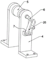
fig. 5 is a schematic structural view of the limiting assembly of the present invention.
Description of reference numerals:
1. a base plate; 2. adjusting a rod; 3. a support platform; 4. a fixing plate; 5. a winding wheel; 6. a rocking handle; 7. a limiting component; 8. a hauling rope; 9. a conveying plate; 10. a sliding sleeve; 11. a slide bar; 12. protecting the fence; 13. an auxiliary wheel; 14. an inner rod; 15. an outer rod; 16. a support plate; 17. a first screw; 18. a threaded sleeve; 19. a handle; 20. a steering wheel; 21. a second screw; 22. a knob; 23. pressing a plate; 24. a limiting block; 25. a reinforcing bar; 26. and a limiting plate.
Detailed Description
The present invention is described in further detail below with reference to figures 1-5.
Referring to fig. 1 and 2, a safe scaffold for building construction comprises a base plate 1, an adjusting rod 2 is installed on the top surface of the base plate 1, the adjusting rod 2 comprises an inner rod 14 and an outer rod 15, the inner rod 14 is installed on the base plate 1, the outer rod 15 is connected to the outer side of the inner rod 14, the outer rod 15 is of a hollow tubular structure and can slide up and down on the inner rod 14, the outer rods 15 are symmetrically arranged on one side of the base plate 1, a supporting plate 16 is connected between the outer rods 15, the bottom of the supporting plate 16 is fixedly connected with a first screw rod 17, the bottom of the first screw rod 17 is in threaded connection with a threaded sleeve 18, the bottom of the threaded sleeve 18 is rotatably installed on the base plate 1 through a bearing, a handle 19 is fixedly connected on the outer wall of the threaded sleeve 18,
through rotatory handle 19, handle 19 drives thread bush 18 and rotates, thread bush 18 carries out screw-thread fit with first screw rod 17 in rotatory, drive first screw rod 17 and remove in thread bush 18, when first screw rod 17 upwards moves, jack-up backup pad 16, and then drive the outer pole 15 of being connected with backup pad 16 and remove, make outer pole 15 slide on interior pole 14, and then can adjust the height of whole regulation pole 2, the user can adjust it according to the construction position.
Referring to fig. 3 and 4, a supporting platform 3 is connected to the top of the adjusting rod 2, two fixing plates 4 are symmetrically connected to the top surface of the supporting platform 3, a winding wheel 5 is rotatably connected between the fixing plates 4, one side of the winding wheel 5 penetrates through the fixing plates 4 and extends to the outer side of the fixing plates 4, a rocking handle 6 is connected to one side of the winding wheel 5 exposed out of the outer side, and a limiting component 7 used for limiting the movement of the rocking handle 6 is arranged at the bottom of the rocking handle 6.
Referring to fig. 5, the position limiting assembly 7 is composed of two position limiting plates 26, each position limiting plate 26 is hinged on the side of the fixed plate 4, a traction rope 8 is wound on the outer side of the winding wheel 5, a conveying plate 9 is fixedly connected to the bottom of the traction rope 8, a sliding sleeve 10 is fixedly connected to one side of the conveying plate 9 close to the adjusting rod 2, a sliding rod 11 is slidably connected inside the sliding sleeve 10, the top of the sliding rod 11 is fixedly connected to the supporting platform 3,
rotatory rocking handle 6, rocking handle 6 drives rolling wheel 5 rotatory, rolling wheel 5 carries out the rolling to haulage rope 8 in the rotation, change haulage rope 8's length in the rolling, and then slide sleeve 10 on the delivery board 9 of driving haulage rope 8 bottom slides on slide bar 11, carry supporting platform 3 department from the bottom of scaffold with delivery board 9, after delivery board 9 reachs the assigned position, two limiting plates 26 of rotation, rotate the both ends of rocking handle 6 with two limiting plates 26, it is spacing to rocking handle 6, can take the construction material on the delivery board 9 this moment.
Further, the bottom of the sliding rod 11 is fixedly connected with a limiting block 24, one side of the sliding sleeve 10 is fixedly connected with a reinforcing rod 25, the other end of the reinforcing rod 25 is fixedly connected to the bottom of the conveying plate 9, the position of the sliding sleeve 10 can be limited through the limiting block 24, complete separation between the sliding sleeve 10 and the sliding rod 11 is avoided, the reinforcing rod 25 can increase supporting force for the conveying plate 9, and the construction material is more stable when being conveyed.
Further, both ends fixedly connected with rail guard 12 of supporting platform 3 installs auxiliary wheel 13 in one side of supporting platform 3, and rail guard 12 can improve the security when constructor operates, and auxiliary wheel 13 can avoid haulage rope 8 direct and supporting platform 3 contact, avoids haulage rope 8 and 3 frictions of supporting platform when adjusting haulage rope 8, leads to haulage rope 8's life-span reduction.
Referring to fig. 1, a steering wheel 20 is connected to the bottom of a base plate 1, a second screw 21 is threadedly connected to both sides of the base plate 1, a knob 22 is connected to the top of the second screw 21, a pressing plate 23 is connected to the bottom of the second screw 21,
the directive wheel 20 is used for shifting holistic scaffold, and when shifting to the rotatory knob 22 behind the assigned position, the knob 22 drives the second screw rod 21 rotatory, drives the clamp plate 23 and the ground contact of bottom, fixes the scaffold to every second screw rod 21 and clamp plate 23 all set up alone, and the distance of adjusting can be adjusted according to the height on ground, and then can be adapted to highly uneven ground.
The implementation principle is as follows: adjust the height of adjusting pole 2 according to the construction height when using, then stand and carry out the construction on supporting platform 3, rocking handle 6 can be rotated to the in-process constructor at the construction, rocking handle 6 drives the rotation of rolling wheel 5, adjust the length of haulage rope 8, and then change the height of delivery board 9, the constructor of bottom can place construction material and construction tool on delivery board 9, carry supporting platform 3 department, the constructor at top takes material or instrument, high durability and convenient operation, save physical power, and more material can once only be carried to delivery board 9, effectively improve the efficiency of construction.
The above are all preferred embodiments of the present invention, and the protection scope of the present invention is not limited thereby, so: all equivalent changes made according to the structure, shape and principle of the utility model are covered by the protection scope of the utility model.
Claims (7)
1. The utility model provides a safe type scaffold frame for construction, includes bottom plate (1), its characterized in that: the top of bottom plate (1) is connected with adjusts pole (2), the top of adjusting pole (2) is connected with supporting platform (3), fixed plate (4) are installed to the top surface of supporting platform (3), it is connected with wind-up wheel (5) to rotate between fixed plate (4), one side of wind-up wheel (5) is connected with rocking handle (6), the bottom of rocking handle (6) is provided with spacing subassembly (7) that are used for fixed rocking handle (6), the outside winding of wind-up wheel (5) has haulage rope (8), the bottom of haulage rope (8) is connected with delivery board (9), one side that delivery board (9) are close to supporting platform (3) is connected with sliding sleeve (10), the inside sliding connection of sliding sleeve (10) has slide bar (11), the bottom at supporting platform (3) is connected to the one end of slide bar (11).
2. The safety scaffold for building construction according to claim 1, wherein: the limiting assembly (7) comprises two limiting plates (26), and the two limiting plates (26) are hinged to the side face of the fixing plate (4).
3. The safety scaffold for building construction according to claim 1, wherein: and two ends of the supporting platform (3) are connected with guard rails (12).
4. The safety scaffold for building construction according to claim 1, wherein: and one side of the supporting platform (3) close to the conveying plate (9) is connected with an auxiliary wheel (13).
5. The safety scaffold for building construction according to claim 1, wherein: adjust pole (2) symmetry and set up the both sides in bottom plate (1), adjust pole (2) including interior pole (14) and outer pole (15), install in the bottom of supporting platform (3) outer pole (15), the inside sliding connection of outer pole (15) has interior pole (14), be connected with backup pad (16) between outer pole (15), the bottom of backup pad (16) is connected with first screw rod (17), the bottom threaded connection of first screw rod (17) has thread bush (18), the bottom of thread bush (18) is rotated and is connected on bottom plate (1), the outer wall of thread bush (18) is fixed with handle (19).
6. The safety scaffold for building construction according to claim 1, wherein: the bottom of bottom plate (1) is connected with directive wheel (20), the both sides threaded connection of bottom plate (1) has second screw rod (21), the top of second screw rod (21) is connected with knob (22), the bottom of second screw rod (21) is connected with clamp plate (23).
7. The safety scaffold for building construction according to claim 1, wherein: the bottom of the sliding rod (11) is connected with a limiting block (24), one side of the sliding sleeve (10) is connected with a reinforcing rod (25), and the other side of the reinforcing rod (25) is connected to the bottom of the conveying plate (9).
Priority Applications (1)
| Application Number | Priority Date | Filing Date | Title |
|---|---|---|---|
| CN202220225529.3U CN216810853U (en) | 2022-01-27 | 2022-01-27 | Safe type scaffold frame for construction |
Applications Claiming Priority (1)
| Application Number | Priority Date | Filing Date | Title |
|---|---|---|---|
| CN202220225529.3U CN216810853U (en) | 2022-01-27 | 2022-01-27 | Safe type scaffold frame for construction |
Publications (1)
| Publication Number | Publication Date |
|---|---|
| CN216810853U true CN216810853U (en) | 2022-06-24 |
Family
ID=82065494
Family Applications (1)
| Application Number | Title | Priority Date | Filing Date |
|---|---|---|---|
| CN202220225529.3U Active CN216810853U (en) | 2022-01-27 | 2022-01-27 | Safe type scaffold frame for construction |
Country Status (1)
| Country | Link |
|---|---|
| CN (1) | CN216810853U (en) |
Cited By (1)
| Publication number | Priority date | Publication date | Assignee | Title |
|---|---|---|---|---|
| CN115559505A (en) * | 2022-11-21 | 2023-01-03 | 江苏中岦绿建建材科技有限公司 | Scaffold for prefabricated house construction |
-
2022
- 2022-01-27 CN CN202220225529.3U patent/CN216810853U/en active Active
Cited By (1)
| Publication number | Priority date | Publication date | Assignee | Title |
|---|---|---|---|---|
| CN115559505A (en) * | 2022-11-21 | 2023-01-03 | 江苏中岦绿建建材科技有限公司 | Scaffold for prefabricated house construction |
Similar Documents
| Publication | Publication Date | Title |
|---|---|---|
| CN216810853U (en) | Safe type scaffold frame for construction | |
| CN212639884U (en) | Building telescopic platform with adjustable | |
| CN105133825A (en) | Multifunctional decoration platform | |
| CN105538237A (en) | Auxiliary device for electric hammer punching | |
| CN211369494U (en) | Combined pile for civil engineering | |
| CN204983582U (en) | Multi -functional fitment platform | |
| CN210508300U (en) | Building platform convenient to use and capable of stretching | |
| CN112209264A (en) | Battery hoisting accessory is used in new energy automobile processing | |
| CN210948724U (en) | Tunnel secondary lining waterproof board laying construction device | |
| CN212802716U (en) | Civil engineering construction supporting structure | |
| CN106276496B (en) | A kind of multi-functional climbing ladder of hand-rail type of suitable the elderly | |
| CN214167237U (en) | Explosion-proof hydraulic lifting platform | |
| CN209259612U (en) | A kind of feeding device for construction | |
| CN211761320U (en) | Retractable reinforcing bar processing platform | |
| CN211899519U (en) | Building construction removes operation platform | |
| CN218264845U (en) | Auxiliary equipment for construction of protective shed | |
| CN215516564U (en) | High stability is lifting support for civil engineering | |
| CN218114895U (en) | Hoisting device is used in building structure construction | |
| CN215565670U (en) | Safe anti-skidding ladder for building decoration | |
| CN214220671U (en) | Safety device is used in hydraulic engineering construction | |
| CN218434564U (en) | Movable portal frame | |
| CN215212198U (en) | A portable scaffold frame for building engineering | |
| CN212919349U (en) | Construction electrical equipment construction device | |
| CN211900638U (en) | Safety support is laid to anchor net | |
| CN217167440U (en) | Split lathe bed gantry side frame structure |
Legal Events
| Date | Code | Title | Description |
|---|---|---|---|
| GR01 | Patent grant | ||
| GR01 | Patent grant |