CN216808027U - Steel construction elevating platform - Google Patents
Steel construction elevating platform Download PDFInfo
- Publication number
- CN216808027U CN216808027U CN202122583822.5U CN202122583822U CN216808027U CN 216808027 U CN216808027 U CN 216808027U CN 202122583822 U CN202122583822 U CN 202122583822U CN 216808027 U CN216808027 U CN 216808027U
- Authority
- CN
- China
- Prior art keywords
- fixedly connected
- base
- threaded rod
- electric telescopic
- framework
- Prior art date
- Legal status (The legal status is an assumption and is not a legal conclusion. Google has not performed a legal analysis and makes no representation as to the accuracy of the status listed.)
- Active
Links
Images


Abstract
The utility model discloses a steel structure lifting platform which comprises a base and a frame body, wherein universal wheels are movably connected at four corners of the bottom of the base, a double-shaft motor is fixedly connected to the top of an inner cavity of the base, a rotating shaft of the double-shaft motor is fixedly connected with a first threaded rod, a threaded pipe is sleeved at one end, far away from the double-shaft motor, of the first threaded rod, one end, far away from the first threaded rod, of the threaded pipe penetrates through the outer part of the base and is fixedly connected with a movable plate, and second threaded rods penetrate through the front side and the rear side of the top of the movable plate. The lifting platform has the advantages of good stability and capability of increasing the supporting area, and solves the problems that the existing steel structure lifting platform has single function, the bottom of the lifting platform is not provided with an auxiliary supporting structure, so that the lifting platform has poor stability, an operator is easy to shake when standing on the lifting platform for operation, certain dangerousness exists, the supporting area cannot be increased according to requirements, and the applicability of the lifting platform is reduced.
Description
Technical Field
The utility model relates to the technical field of steel structures, in particular to a steel structure lifting platform.
Background
The steel structure is a structure formed by steel materials, is one of main building structure types, mainly comprises steel beams, steel columns, steel trusses and other members made of section steel, steel plates and the like, and adopts rust removing and preventing processes of silanization, pure manganese phosphating, washing and drying, galvanization and the like.
The existing steel structure lifting platform is single in function, an auxiliary supporting structure is not arranged at the bottom of the lifting platform, so that the lifting platform is poor in stability, an operator can shake easily when standing on the lifting platform for operation, certain danger exists, the supporting area cannot be increased according to requirements, and the applicability of the lifting platform is reduced.
SUMMERY OF THE UTILITY MODEL
The utility model aims to provide a steel structure lifting platform which has the advantages of good stability and capability of increasing the supporting area due to the fact that the lifting platform is supported by the aid of the bottom, and solves the problems that an existing steel structure lifting platform is single in function, poor in stability and prone to shaking and having certain danger due to the fact that an operator stands on the lifting platform to operate, cannot increase the supporting area as required and reduces the applicability of the lifting platform due to the fact that an auxiliary supporting structure is not arranged at the bottom of the lifting platform.
In order to achieve the purpose, the utility model provides the following technical scheme: a steel structure lifting platform comprises a base and a frame body, wherein universal wheels are movably connected with four corners of the bottom of the base, a double-shaft motor is fixedly connected with the top of an inner cavity of the base, a first threaded rod is fixedly connected with a rotating shaft of the double-shaft motor, a threaded sleeve is arranged at one end, far away from the double-shaft motor, of the first threaded rod, one end, far away from the first threaded rod, of the threaded pipe penetrates through the outer part of the base and is fixedly connected with a movable plate, a second threaded rod penetrates through the front side and the rear side of the top of the movable plate, the bottom of the second threaded rod penetrates through the bottom of the movable plate and is in threaded connection with the movable plate, a supporting plate is fixedly connected with the bottom of the second threaded rod, first connecting rods are movably connected with four corners of the top of the base and four corners of the bottom of the frame body through rotating shafts, and the upper and lower first connecting rods are movably connected through rotating shafts, first electric telescopic handle and second electric telescopic handle have through pivot swing joint respectively between two horizontal head rods, the equal swing joint in both sides of framework inner chamber has the removal frame, one side of removing the frame extends to the outside of framework, the both sides of framework bottom are all through a piece fixedly connected with third electric telescopic handle, third electric telescopic handle's one end fixedly connected with connecting plate, the top of connecting plate with remove frame fixed connection.
Preferably, the bottom of the inner cavity of the base is provided with a sliding groove, the bottom of the threaded pipe is fixedly connected with a sliding rod, and the bottom of the sliding rod extends to the inner cavity of the sliding groove.
Preferably, the top of the second threaded rod is fixedly connected with a turntable, and the bottom of the supporting plate is fixedly connected with an anti-slip pad.
Preferably, the front and the back of framework all are through a piece fixedly connected with guide bar, the surface cover of guide bar is equipped with the uide bushing, the fixed surface of guide bar is connected with the second connecting rod, one side and the carriage fixed connection of uide bushing are kept away from to the second connecting rod.
Preferably, the surface of the threaded pipe is movably connected with the joint of the base, and the surface of the movable frame is movably connected with the joint of the inner wall of the frame body.
Preferably, the inner wall fixedly connected with battery of framework, the positive top fixedly connected with controller of framework, the input and the battery electricity of controller are connected, the output of controller respectively with first electric telescopic handle, second electric telescopic handle, third electric telescopic handle and double-shaft motor electric connection.
Compared with the prior art, the utility model has the following beneficial effects:
1. the lifting platform has the advantages of being good in stability and capable of increasing the supporting area, and solves the problems that an existing steel structure lifting platform is single in function, an auxiliary supporting structure is not arranged at the bottom, the lifting platform is poor in stability, an operator is prone to shaking when standing on the lifting platform to operate, the supporting area cannot be increased according to requirements, and the applicability of the lifting platform is reduced.
2. According to the utility model, the threaded pipe can be supported in a balanced manner by arranging the sliding chute and the sliding rod, so that the threaded pipe can move transversely conveniently, the roughness of the bottom of the supporting plate is increased by arranging the anti-slip pad, the friction force between the supporting plate and the ground is increased, the base is conveniently and stably supported, the second threaded rod can be conveniently driven to rotate by arranging the turntable, the movable frame can be supported in a balanced manner by arranging the guide rod, the guide sleeve and the second connecting rod, so that the transverse movement of the movable frame is convenient, and the electric energy can be provided by arranging the storage battery.
Drawings
FIG. 1 is a schematic cross-sectional view of the structure of the present invention;
FIG. 2 is a schematic top view of the structure of the present invention;
FIG. 3 is a schematic front view of the structure of the present invention;
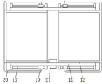
fig. 4 is a perspective view showing the connection between the frame body and the movable frame according to the present invention.
In the figure: the device comprises a base 1, universal wheels 2, a double-shaft motor 3, a first threaded rod 4, a threaded pipe 5, a movable plate 6, a second threaded rod 7, a supporting plate 8, a first connecting rod 9, a first electric telescopic rod 10, a second electric telescopic rod 11, a frame 12, a movable frame 13, a third electric telescopic rod 14, a connecting plate 15, a sliding groove 16, a sliding rod 17, a guide rod 18, a guide sleeve 19, a second connecting rod 20 and a controller 21.
Detailed Description
The technical solutions in the embodiments of the present invention will be clearly and completely described below with reference to the drawings in the embodiments of the present invention, and it is obvious that the described embodiments are only a part of the embodiments of the present invention, and not all of the embodiments. All other embodiments, which can be derived by a person skilled in the art from the embodiments given herein without making any creative effort, shall fall within the protection scope of the present invention.
In the description of the present invention, it should be noted that the terms "upper", "lower", "inner", "outer", "front", "rear", "both ends", "one end", "the other end", and the like indicate orientations or positional relationships based on the orientations or positional relationships shown in the drawings, and are only for convenience of description and simplification of description, but do not indicate or imply that the device or element referred to must have a specific orientation, be constructed and operated in a specific orientation, and thus, should not be construed as limiting the present invention. Furthermore, the terms "first" and "second" are used for descriptive purposes only and are not to be construed as indicating or implying relative importance.
In the description of the present invention, it is to be noted that, unless otherwise explicitly specified or limited, the terms "mounted", "provided", "connected", and the like are to be construed broadly, such as "connected", which may be fixedly connected, detachably connected, or integrally connected; can be mechanically or electrically connected; they may be connected directly or indirectly through intervening media, or they may be interconnected between two elements. The specific meanings of the above terms in the present invention can be understood in specific cases to those skilled in the art.
The base 1, the universal wheel 2, the double-shaft motor 3, the first threaded rod 4, the threaded pipe 5, the moving plate 6, the second threaded rod 7, the supporting plate 8, the first connecting rod 9, the first electric telescopic rod 10, the second electric telescopic rod 11, the frame body 12, the moving frame 13, the third electric telescopic rod 14, the connecting plate 15, the sliding chute 16, the sliding rod 17, the guide rod 18, the guide sleeve 19, the second connecting rod 20 and the controller 21 are all universal standard parts or parts known by a person skilled in the art, and the structure and the principle of the utility model can be known by technical manuals or conventional experimental methods.
Referring to fig. 1-4, a steel structure lifting platform comprises a base 1 and a frame 12, universal wheels 2 are movably connected at four corners of the bottom of the base 1, a double-shaft motor 3 is fixedly connected at the top of the inner cavity of the base 1, a first threaded rod 4 is fixedly connected to the rotating shaft of the double-shaft motor 3, a threaded pipe 5 is sleeved at one end of the first threaded rod 4 far away from the double-shaft motor 3, one end of the threaded pipe 5 far away from the first threaded rod 4 penetrates through the outer part of the base 1 and is fixedly connected with a moving plate 6, a second threaded rod 7 penetrates through the front side and the rear side of the top of the moving plate 6, the bottom of the second threaded rod 7 penetrates through the bottom of the moving plate 6 and is in threaded connection with the moving plate 6, a support plate 8 is fixedly connected to the bottom of the second threaded rod 7, first connecting rods 9 are movably connected at four corners of the top of the base 1 and four corners of the bottom of the frame 12 through rotating shafts, and upper and lower first connecting rods 9 are movably connected through rotating shafts, a first electric telescopic rod 10 and a second electric telescopic rod 11 are respectively and movably connected between the two transverse first connecting rods 9 through a rotating shaft, two sides of an inner cavity of the frame body 12 are respectively and movably connected with a movable frame 13, one side of the movable frame 13 extends to the outside of the frame body 12, two sides of the bottom of the frame body 12 are respectively and fixedly connected with a third electric telescopic rod 14 through a supporting block, one end of the third electric telescopic rod 14 is fixedly connected with a connecting plate 15, the top of the connecting plate 15 is fixedly connected with the movable frame 13, the bottom of the inner cavity of the base 1 is provided with a sliding groove 16, the bottom of the threaded pipe 5 is fixedly connected with a sliding rod 17, the bottom of the sliding rod 17 extends to the inner cavity of the sliding groove 16, the threaded pipe 5 can be balanced supported through the arrangement of the sliding groove 16 and the sliding rod 17, the transverse movement of the threaded pipe 5 is convenient, the top of the second threaded rod 7 is fixedly connected with a rotating disc, and the bottom of the supporting plate 8 is fixedly connected with an anti-slip mat, the roughness of the bottom of the supporting plate 8 is increased by arranging the anti-slip pad, the friction force between the supporting plate 8 and the ground is increased, the base 1 is conveniently and stably supported, the second threaded rod 7 is conveniently driven to rotate by arranging the turntable, the front surface and the back surface of the frame body 12 are both fixedly connected with the guide rod 18 through the support block, the surface of the guide rod 18 is sleeved with the guide sleeve 19, the surface of the guide rod 18 is fixedly connected with the second connecting rod 20, one side of the second connecting rod 20, far away from the guide sleeve 19, is fixedly connected with the moving frame 13, the moving frame 13 can be supported in a balanced manner by arranging the guide rod 18, the guide sleeve 19 and the second connecting rod 20, the transverse movement of the moving frame 13 is convenient, the joint of the surface of the threaded pipe 5 and the base 1 is movably connected, the joint of the surface of the moving frame 13 and the inner wall of the frame body 12 is movably connected, the inner wall of the frame body 12 is fixedly connected with the storage battery, through setting up the battery, can provide the electric energy, the positive top of framework 12 is fixedly connected with controller 21, the input of controller 21 is connected with the battery electricity, the output of controller 21 is connected with first electric telescopic handle 10, second electric telescopic handle 11, third electric telescopic handle 14 and biax motor 3 electrical behavior respectively, cooperate through base 1, universal wheel 2, biax motor 3, first threaded rod 4, screwed pipe 5, movable plate 6, second threaded rod 7, backup pad 8, first connecting rod 9, first electric telescopic handle 10, second electric telescopic handle 11, framework 12, movable frame 13, third electric telescopic handle 14 and connecting plate 15, possess bottom auxiliary support elevating platform, stability is good, can increase the advantage of the supporting area, it is single to solve the existing steel structure elevating platform function, there is no auxiliary support structure in the bottom, make the elevating platform poor stability, the operator stands and rocks when the operation on the elevating platform easily, has certain danger, can not increase the support area according to the demand, has reduced the problem of elevating platform suitability.
When the device is used, when the bottom supporting area is increased, the controller 21 controls the operation of the double-shaft motor 3 to drive the first threaded rod 4 to rotate, the first threaded rod 4 is in threaded connection with the threaded pipe 5, the threaded pipe 5 drives the movable plate 6 to move away from the base 1, the rotary turntable drives the second threaded rod 7 to rotate, the second threaded rod 7 is in threaded connection with the movable plate 6, the second threaded rod 7 drives the support plate 8 and the anti-skid pad to move downwards to be in contact with the ground, the base 1 is stably supported, the controller 21 controls the upper and lower first electric telescopic rods 10 to extend to push one end of the first connecting rod 9 to move, the controller 21 controls the second electric telescopic rod 11 to contract to drive one ends of the first connecting rods 9 on two sides to move close to each other, the first connecting rod 9 pushes the frame body 12 to move upwards, the height of the frame body 12 can be adjusted, when the supporting area is increased, the controller 21 controls the third electric telescopic rod 14 to extend to drive the connecting plate 15 and the movable frame 13 to move, the moving frame 13 is extended to increase the supporting area.
In summary, the following steps: this steel construction elevating platform, through base 1, universal wheel 2, double-shaft motor 3, first threaded rod 4, screwed pipe 5, movable plate 6, second threaded rod 7, backup pad 8, head rod 9, first electric telescopic handle 10, second electric telescopic handle 11, framework 12, remove frame 13, third electric telescopic handle 14 and connecting plate 15 cooperate, current steel construction elevating platform function singleness has been solved, the bottom does not have auxiliary support structure, make elevating platform poor stability, the operator stands and produces easily when operating on the elevating platform and rocks, there is certain danger, can not increase the bearing area according to the demand, the problem of elevating platform suitability has been reduced.
Although embodiments of the present invention have been shown and described, it will be appreciated by those skilled in the art that changes, modifications, substitutions and alterations can be made in these embodiments without departing from the principles and spirit of the utility model, the scope of which is defined in the appended claims and their equivalents.
Claims (6)
1. The utility model provides a steel construction elevating platform, includes base (1) and framework (12), its characterized in that: the all swing joint in four corners of base (1) bottom has universal wheel (2), the top fixedly connected with double-shaft motor (3) of base (1) inner chamber, the first threaded rod (4) of pivot fixedly connected with of double-shaft motor (3), the one end screw thread cover that double-shaft motor (3) were kept away from in first threaded rod (4) is equipped with screwed pipe (5), the one end that first threaded rod (4) were kept away from in screwed pipe (5) runs through to outside and fixedly connected with movable plate (6) of base (1), the front side and the rear side at movable plate (6) top all run through and are provided with second threaded rod (7), the bottom of second threaded rod (7) runs through to the bottom of movable plate (6) and with movable plate (6) threaded connection, the bottom fixedly connected with backup pad (8) of second threaded rod (7), the four corners at base (1) top and the four corners of framework (12) bottom all have head rod (9) through pivot swing joint ) Two upper and lower head rods (9) have first electric telescopic handle (10) and second electric telescopic handle (11) through pivot swing joint respectively between two horizontal head rods (9), the equal swing joint in both sides of framework (12) inner chamber has removal frame (13), one side of removing frame (13) extends to the outside of framework (12), the both sides of framework (12) bottom are all through a piece fixedly connected with third electric telescopic handle (14), one end fixedly connected with connecting plate (15) of third electric telescopic handle (14), the top and the removal frame (13) fixed connection of connecting plate (15).
2. The steel structure elevating platform of claim 1, characterized in that: spout (16) have been seted up to the bottom of base (1) inner chamber, the bottom fixedly connected with slide bar (17) of screwed pipe (5), the bottom of slide bar (17) extends to the inner chamber of spout (16).
3. The steel structure elevating platform of claim 1, characterized in that: the top of the second threaded rod (7) is fixedly connected with a turntable, and the bottom of the supporting plate (8) is fixedly connected with an anti-slip pad.
4. The steel structure elevating platform of claim 1, characterized in that: the front and the back of framework (12) all are through a piece fixedly connected with guide bar (18), the surface cover of guide bar (18) is equipped with uide bushing (19), the fixed surface of guide bar (18) is connected with second connecting rod (20), one side and removal frame (13) fixed connection of uide bushing (19) are kept away from in second connecting rod (20).
5. The steel structure elevating platform of claim 1, characterized in that: the surface of the threaded pipe (5) is movably connected with the joint of the base (1), and the surface of the movable frame (13) is movably connected with the joint of the inner wall of the frame body (12).
6. The steel structure elevating platform of claim 1, characterized in that: the inner wall fixedly connected with battery of framework (12), the positive top fixedly connected with controller (21) of framework (12), the input and the battery electricity of controller (21) are connected, the output of controller (21) respectively with first electric telescopic handle (10), second electric telescopic handle (11), third electric telescopic handle (14) and biax motor (3) electric connection.
Priority Applications (1)
| Application Number | Priority Date | Filing Date | Title |
|---|---|---|---|
| CN202122583822.5U CN216808027U (en) | 2021-10-26 | 2021-10-26 | Steel construction elevating platform |
Applications Claiming Priority (1)
| Application Number | Priority Date | Filing Date | Title |
|---|---|---|---|
| CN202122583822.5U CN216808027U (en) | 2021-10-26 | 2021-10-26 | Steel construction elevating platform |
Publications (1)
| Publication Number | Publication Date |
|---|---|
| CN216808027U true CN216808027U (en) | 2022-06-24 |
Family
ID=82049150
Family Applications (1)
| Application Number | Title | Priority Date | Filing Date |
|---|---|---|---|
| CN202122583822.5U Active CN216808027U (en) | 2021-10-26 | 2021-10-26 | Steel construction elevating platform |
Country Status (1)
| Country | Link |
|---|---|
| CN (1) | CN216808027U (en) |
-
2021
- 2021-10-26 CN CN202122583822.5U patent/CN216808027U/en active Active
Similar Documents
| Publication | Publication Date | Title |
|---|---|---|
| CN204497630U (en) | A kind of highly compatible for circuit breaker and porcelain vase overturns car | |
| CN216808027U (en) | Steel construction elevating platform | |
| CN211554267U (en) | High-power supply maintenance platform | |
| CN111561215B (en) | Telegraph pole support | |
| CN111519500A (en) | Telescopic concrete road trowelling machine | |
| CN211974246U (en) | Hydraulic engineering construction auxiliary assembly that ascends a height | |
| CN110921529A (en) | Stacking device for power equipment | |
| CN217596029U (en) | Building steel cutting device | |
| CN214989880U (en) | Movable type lifts by crane overhauls support | |
| CN214001758U (en) | Pipeline spare arrangement frame for building engineering | |
| CN213445976U (en) | Steel structure supporting device for marine engineering construction of ship | |
| CN213319957U (en) | Auxiliary workbench for product design | |
| CN212665331U (en) | Longitudinal beam assembly turnover welding device | |
| CN212425210U (en) | Driving grab bucket feed arrangement | |
| CN214124846U (en) | Mixed type static compensation device | |
| CN216810856U (en) | Movable operation frame for constructional engineering | |
| CN219585791U (en) | Lifting table for power maintenance | |
| CN213921157U (en) | Water conservancy pile foundation handling device | |
| CN215443198U (en) | A assembled platform of unloading safely for construction | |
| CN212197260U (en) | Logistics management device | |
| CN216887974U (en) | MVR evaporator rapid transport device | |
| CN220467436U (en) | Material lifting device for building construction | |
| CN216472118U (en) | Supporting device for installation of large-scale factory building | |
| CN217782959U (en) | Safety device for assembly type building | |
| CN215828304U (en) | Lifting device for decoration |
Legal Events
| Date | Code | Title | Description |
|---|---|---|---|
| GR01 | Patent grant | ||
| GR01 | Patent grant |