CN216804562U - Chinese patent medicine forming mechanism for tablet press - Google Patents
Chinese patent medicine forming mechanism for tablet press Download PDFInfo
- Publication number
- CN216804562U CN216804562U CN202123054351.5U CN202123054351U CN216804562U CN 216804562 U CN216804562 U CN 216804562U CN 202123054351 U CN202123054351 U CN 202123054351U CN 216804562 U CN216804562 U CN 216804562U
- Authority
- CN
- China
- Prior art keywords
- shaped seat
- cavity
- chinese patent
- patent medicine
- fixed mounting
- Prior art date
- Legal status (The legal status is an assumption and is not a legal conclusion. Google has not performed a legal analysis and makes no representation as to the accuracy of the status listed.)
- Active
Links
Images

Landscapes
- Medicines Containing Plant Substances (AREA)
Abstract
The utility model relates to the technical field of Chinese patent medicine processing, and discloses a forming mechanism for a Chinese patent medicine tablet press, which comprises a base, wherein a U-shaped seat is arranged at the top of the base, a tablet pressing assembly with one end extending into the U-shaped seat is arranged at the top of the U-shaped seat, a lower die is arranged on the inner bottom wall of the U-shaped seat, and a first cavity positioned below the lower die is arranged in the U-shaped seat. This forming mechanism for Chinese patent medicine tablet press, make second conical gear drive first conical gear meshing rotation through rotating the dwang, make the threaded rod rotate in step, drive the screw block and move down on the slide bar in the threaded rod pivoted, make the pulley promote first wedge plate and second wedge plate and remove, promote the ejector pin when second wedge plate removes and shift up, it is with tablet and the bed die separation after the preforming shaping to control two ejector pins to shift up the jacking stripper plate, realize the quick drawing of patterns of tablet, be favorable to improving preforming efficiency.
Description
Technical Field
The utility model relates to the technical field of Chinese patent medicine processing, in particular to a forming mechanism for a Chinese patent medicine tabletting machine.
Background
The Chinese patent medicine tablet press is indispensable equipment in the production of tablets, and it is through placing powder inside the mould, then carries out the punching press through the top preforming to make the tablet at the inside shaping of mould, therefore can know that present Chinese patent medicine is forming mechanism for tablet press satisfies people's demand basically, but still has some problems.
After the existing Chinese patent medicine tablet press is molded in a die, because the tablet is tightly combined with the die, the tablet cannot be taken out of the die quickly in actual production, so that the tablet cannot be released from the die conveniently, and the tablet pressing efficiency is influenced, and therefore a molding mechanism for the Chinese patent medicine tablet press is urgently needed to solve the problems.
SUMMERY OF THE UTILITY MODEL
Technical problem to be solved
Aiming at the defects of the prior art, the utility model provides a forming mechanism for a Chinese patent medicine tablet press, which has the advantage of convenience in demoulding and solves the problems that after the Chinese patent medicine tablet press is formed in a mould, the tablet cannot be quickly taken out of the mould in actual production due to the close combination of the tablet and the mould, so that the demoulding is inconvenient and the tabletting efficiency is influenced.
(II) technical scheme
In order to realize the purpose of facilitating demoulding, the utility model provides the following technical scheme: a forming mechanism for a Chinese patent medicine tabletting machine comprises a base, wherein a U-shaped seat is arranged at the top of the base, a tabletting assembly with one end extending to the inside of the U-shaped seat is arranged at the top of the U-shaped seat, a lower die is arranged on the inner bottom wall of the U-shaped seat, a first cavity below the lower die is arranged inside the U-shaped seat, a transverse plate is arranged between the left side and the right side of the inner wall of the first cavity, a second cavity below the first cavity is arranged inside the U-shaped seat, a pushing assembly with one end extending to the inside of the second cavity is arranged between the transverse plate and the inner bottom wall of the first cavity, jacking assemblies respectively connected with the left end and the right end of the inner wall of the first cavity in a sliding manner are arranged on the left side and the right side of the inner wall of the first cavity, one end of the top of each jacking assembly penetrates through the transverse plate and extends to the inside of the lower die and is attached to the inner bottom wall of the lower die, the right side of the U-shaped seat is provided with a rotating assembly, one end of the rotating assembly extends into the second cavity and is movably connected with the left side of the inner wall of the second cavity, and the rotating assembly is located below the pushing assembly and meshed with the pushing assembly.
Preferably, the preforming subassembly includes the pneumatic cylinder, the top fixed mounting of U-shaped seat has one end to extend to its inside pneumatic cylinder, the output fixed mounting of pneumatic cylinder has the mounting panel, the bottom fixed mounting of mounting panel has the mould.
Preferably, the promotion subassembly includes the threaded rod, the bottom movable mounting of diaphragm has one end to extend to the inside threaded rod of second cavity, the bottom fixed mounting of threaded rod has first conical gear, fixed mounting has quantity between the bottom of diaphragm and the interior diapire of first cavity and is two and be located the slide bar of the threaded rod left and right sides respectively, the outside screw thread of threaded rod install about both ends respectively with two slide bar sliding connection's thread block, the equal fixed mounting in left and right sides of thread block has the pulley, movable mounting has the looks dorsal part that is located two pulleys respectively between the inner wall of first cavity around both sides and with pulley sliding connection's first wedge, two the equal fixed mounting in the back of the body of first wedge has one end and first cavity's interior diapire sliding connection's second wedge.
Preferably, the jacking subassembly includes the slide, the equal movable mounting in the inner wall left and right sides of first cavity has the slide, two the equal fixed mounting in opposite side of slide has one end to run through the diaphragm and extend to the inside ejector pin of bed die, the bottom fixed mounting of ejector pin has the gyro wheel with second wedge sliding connection, the left side the top fixed mounting of ejector pin has the top fixed connection's of one end and right side ejector pin stripper plate, the bottom of stripper plate is laminated with the inner bottom wall of bed die mutually.
Preferably, the rotating assembly comprises a rotating rod, one end of the right side of the U-shaped seat is movably mounted with the rotating rod, the rotating rod is movably connected with the left side of the inner wall of the second cavity, and the outer fixed mounting of the rotating rod is provided with a second bevel gear meshed with the first bevel gear.
Preferably, the bottoms of the first wedge-shaped plate and the second wedge-shaped plate are fixedly provided with sliding blocks, one ends of the sliding blocks are connected with the inner bottom wall of the first cavity in a sliding mode.
(III) advantageous effects
Compared with the prior art, the utility model provides a forming mechanism for a Chinese patent medicine tabletting machine, which has the following beneficial effects:
this forming mechanism for chinese patent drug tabletting machine, make second bevel gear drive first bevel gear meshing rotation through rotating the dwang, make the threaded rod rotate in step, drive the screw thread piece when the threaded rod pivoted and move down on the slide bar, make the pulley promote first wedge board and second wedge board and remove, it shifts up to promote the ejector pin when second wedge board removes, it shifts up to shift up the tablet and the bed die separation of ejector plate after with the preforming shaping to control two ejector pins, realize the quick drawing of patterns of tablet, be favorable to improving sheeting efficiency.
Drawings
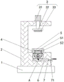
FIG. 1 is a schematic front view of the structure of the present invention;
FIG. 2 is an enlarged view of the point A in FIG. 1.
In the figure: the device comprises a base 1, a U-shaped seat 2, a tabletting assembly 3, a hydraulic cylinder 31, a mounting plate 32, an upper die 33, a lower die 4, a jacking assembly 5, a stripper plate 51, a mandril 52, a sliding plate 53, a second chamber 6, a rotating assembly 7, a rotating rod 71, a second conical gear 72, a transverse plate 8, a pushing assembly 9, a threaded rod 91, a threaded block 92, a pulley 92, a second wedge plate 94, a first wedge plate 95, a sliding rod 96, a first conical gear 97 and a first chamber 10.
Detailed Description
The technical solutions in the embodiments of the present invention will be clearly and completely described below with reference to the drawings in the embodiments of the present invention, and it is obvious that the described embodiments are only a part of the embodiments of the present invention, and not all of the embodiments. All other embodiments, which can be derived by a person skilled in the art from the embodiments given herein without making any creative effort, shall fall within the protection scope of the present invention.
Referring to fig. 1-2, the present invention provides the following technical solutions: the utility model provides a forming mechanism for Chinese patent medicine tablet press, includes base 1, and the top fixed mounting of base 1 has U-shaped seat 2, and the top fixed mounting of U-shaped seat 2 has one end to extend to its inside preforming subassembly 3.
Preforming subassembly 3 includes pneumatic cylinder 31, the top fixed mounting of U-shaped seat 2 has one end to extend to its inside pneumatic cylinder 31, the output fixed mounting of pneumatic cylinder 31 has mounting panel 32, the bottom fixed mounting of mounting panel 32 has last mould 33, the inner diapire fixed mounting of U-shaped seat 2 has bed die 4, first cavity 10 that is located bed die 4 below is seted up to the inside of U-shaped seat 2, fixed mounting has diaphragm 8 between the inner wall left and right sides of first cavity 10, second cavity 6 that is located first cavity 10 below is seted up to the inside of U-shaped seat 2, fixed mounting has one end to extend to the inside pushing assembly 9 of second cavity 6 between the inner diapire of diaphragm 8 and first cavity 10.
Pushing assembly 9 includes threaded rod 91, the bottom movable mounting of diaphragm 8 has threaded rod 91 that one end extends to inside second chamber 6, the bottom fixed mounting of threaded rod 91 has first bevel gear 97, fixed mounting has between the bottom of diaphragm 8 and the inner bottom wall of first chamber 10 that quantity is two and be located the slide bar 96 of the threaded rod 91 left and right sides respectively, both ends respectively with two slide bar 96 sliding connection's screw block 92 about the outside threaded mounting of threaded rod 91, the equal fixed mounting in left and right sides of screw block 92 has pulley 93, movable mounting has the first wedge-shaped plate 95 that is located the dorsal part of two pulleys 93 respectively and with pulley 93 sliding connection between the both sides around the inner wall of first chamber 10, the equal fixed mounting in the back of the body of two first wedge-shaped plates 95 has one end and first chamber 10's inner bottom wall sliding connection's second wedge-shaped plate 94, the equal fixed mounting in bottom of first wedge-shaped plate 95 and second wedge-shaped plate 94 has one end and first chamber 10's inner bottom wall sliding connection The slider of, the equal slidable mounting in inner wall left and right sides of first cavity 10 have respectively with push assembly 9 about both ends sliding connection's jacking subassembly 5, the top one end of jacking subassembly 5 runs through diaphragm 8 and extends to the inside of bed die 4 and with the interior bottom wall laminating of bed die 4.
Jacking subassembly 5 includes slide 53, the equal movable mounting in inner wall left and right sides of first cavity 10 has slide 53, the equal fixed mounting of opposite side of two slide 53 has one end to run through diaphragm 8 and extend to the inside ejector pin 52 of bed die 4, the bottom fixed mounting of ejector pin 52 has the gyro wheel 54 with second wedge 94 sliding connection, the top fixed mounting of left side ejector pin 52 has one end and the top fixed connection's of right side ejector pin 52 stripper plate 51, the bottom of stripper plate 51 is laminated with the inner bottom wall of bed die 4, the right side movable mounting of U-shaped seat 2 has one end to extend to the inside of second cavity 6 and with the rotating assembly 7 of the inner wall left side movable connection of second cavity 6, rotating assembly 7 is located the below of pushing assembly 9 and meshes with pushing assembly 9 mutually.
The rotating assembly 7 comprises a rotating rod 71, the right side of the U-shaped seat 2 is movably provided with the rotating rod 71, one end of the rotating rod 71 extends into the second chamber 6 and is movably connected with the left side of the inner wall of the second chamber 6, and the outer part of the rotating rod 71 is fixedly provided with a second bevel gear 72 meshed with the first bevel gear 97.
Make second bevel gear 72 drive first bevel gear 97 meshing rotation through rotating dwang 71, make threaded rod 91 synchronous revolution, drive screw block 92 and move down on slide bar 96 in threaded rod 91 pivoted, make pulley 92 promote first wedge-shaped plate 95 and second wedge-shaped plate 94 and move, second wedge-shaped plate 94 is promoting ejector pin 52 and is shifting up when moving, two ejector pins 52 of left and right sides are shifting up the tablet that the jacking stripper plate 51 will carry out the preforming shaping and are separated with lower mould 4, realize the quick drawing of patterns of tablet, be favorable to improving preforming efficiency.
In conclusion, the forming mechanism for the Chinese patent medicine tabletting machine makes the second bevel gear 72 drive the first bevel gear 97 to rotate in an engaged manner by rotating the rotating rod 71, so that the threaded rod 91 rotates synchronously, the threaded rod 91 rotates and simultaneously drives the threaded block 92 to move downwards on the sliding rod 96, so that the pulley 92 pushes the first wedge-shaped plate 95 and the second wedge-shaped plate 94 to move, the second wedge-shaped plate 94 pushes the ejector rods 52 to move upwards when moving, the left ejector rod 52 and the right ejector rod 52 move upwards to lift the stripper plate 51 to separate tablets formed by tabletting from the lower die 4, the rapid demoulding of the tablets is realized, the tabletting efficiency is improved, the problem that the traditional Chinese patent medicine tablet press is pressed and formed in the die is solved, because the tablet and the inseparable combination of mould lead to the tablet in actual production the product can't be taken out from the mould fast, the drawing of patterns of being inconvenient for, and then influence the problem of preforming efficiency.
It is noted that, herein, relational terms such as first and second, and the like may be used solely to distinguish one entity or action from another entity or action without necessarily requiring or implying any actual such relationship or order between such entities or actions. Also, the terms "comprises," "comprising," or any other variation thereof, are intended to cover a non-exclusive inclusion, such that a process, method, article, or apparatus that comprises a list of elements does not include only those elements but may include other elements not expressly listed or inherent to such process, method, article, or apparatus. Without further limitation, an element defined by the phrase "comprising an … …" does not exclude the presence of other identical elements in a process, method, article, or apparatus that comprises the element.
Although embodiments of the present invention have been shown and described, it will be appreciated by those skilled in the art that changes, modifications, substitutions and alterations can be made in these embodiments without departing from the principles and spirit of the utility model, the scope of which is defined in the appended claims and their equivalents.
Claims (6)
1. The utility model provides a forming mechanism for chinese patent medicine preforming machine, includes base (1), the top of base (1) is provided with U-shaped seat (2), the top of U-shaped seat (2) is provided with one end and extends to its inside preforming subassembly (3), the inner diapire of U-shaped seat (2) is provided with bed die (4), its characterized in that: the inside of U-shaped seat (2) is provided with first cavity (10) that is located bed die (4) below, be provided with diaphragm (8) between the inner wall left and right sides of first cavity (10), the inside of U-shaped seat (2) is provided with second cavity (6) that are located first cavity (10) below, be provided with between the inner bottom wall of diaphragm (8) and first cavity (10) one end extend to push assembly (9) that extend to second cavity (6) inside, the inner wall left and right sides of first cavity (10) all is provided with respectively with push assembly (9) about both ends sliding connection's jacking subassembly (5), the top one end of jacking subassembly (5) runs through diaphragm (8) and extends to the inside of bed die (4) and with the inner bottom wall laminating of bed die (4), the right side of U-shaped seat (2) is provided with one end extend to the inside of second cavity (6) and with the inner wall left side swing joint of second cavity (6) inner wall The rotating assembly (7) is positioned below the pushing assembly (9) and is meshed with the pushing assembly (9).
2. The forming mechanism for Chinese patent medicine tabletting machine according to claim 1, characterized in that: preforming subassembly (3) include pneumatic cylinder (31), the top fixed mounting of U-shaped seat (2) has one end to extend to its inside pneumatic cylinder (31), the output fixed mounting of pneumatic cylinder (31) has mounting panel (32), the bottom fixed mounting of mounting panel (32) has last mould (33).
3. The forming mechanism for Chinese patent medicine tabletting machine according to claim 1, characterized in that: the pushing component (9) comprises a threaded rod (91), one end of the bottom movable mounting of the transverse plate (8) extends to the threaded rod (91) inside the second chamber (6), a first bevel gear (97) is fixedly mounted at the bottom of the threaded rod (91), a sliding rod (96) with two quantities is fixedly mounted between the bottom of the transverse plate (8) and the inner bottom wall of the first chamber (10) and respectively located at the left side and the right side of the threaded rod (91), a threaded block (92) with two sliding rods (96) and respectively located at the left end and the right end is mounted on the outer thread of the threaded rod (91), pulleys (93) are fixedly mounted at the left side and the right end of the threaded block (92), a first wedge-shaped plate (95) which is respectively located at the back side of the two pulleys (93) and is slidably connected with the pulleys (93) is movably mounted between the front side and the back side of the inner wall of the first chamber (10), two the equal fixed mounting in the back of the body side of first wedge plate (95) has one end and first chamber (10) inner bottom wall sliding connection's second wedge plate (94).
4. The forming mechanism for Chinese patent medicine tabletting machine according to claim 3, characterized in that: jacking subassembly (5) include slide (53), the equal movable mounting in inner wall left and right sides of first cavity (10) has slide (53), two the equal fixed mounting in opposite side of slide (53) has one end to run through diaphragm (8) and extend to inside ejector pin (52) of bed die (4), the bottom fixed mounting of ejector pin (52) has gyro wheel (54) with second wedge plate (94) sliding connection, the left side the top fixed mounting of ejector pin (52) has top fixed connection's of one end and right side ejector pin (52) stripper plate (51), the bottom of stripper plate (51) is laminated with the inner bottom wall of bed die (4) mutually.
5. The forming mechanism for Chinese patent medicine tabletting machine according to claim 3, characterized in that: rotating assembly (7) are including dwang (71), the right side movable mounting of U-shaped seat (2) have one end extend to the inside of second chamber (6) and with inner wall left side swing joint's of second chamber (6) dwang (71), the outside fixed mounting of dwang (71) has second conical gear (72) with first conical gear (97) engaged with.
6. The forming mechanism for Chinese patent medicine tabletting machine according to claim 3, characterized in that: and the bottoms of the first wedge-shaped plate (95) and the second wedge-shaped plate (94) are fixedly provided with sliding blocks, one ends of which are in sliding connection with the inner bottom wall of the first chamber (10).
Priority Applications (1)
| Application Number | Priority Date | Filing Date | Title |
|---|---|---|---|
| CN202123054351.5U CN216804562U (en) | 2021-12-07 | 2021-12-07 | Chinese patent medicine forming mechanism for tablet press |
Applications Claiming Priority (1)
| Application Number | Priority Date | Filing Date | Title |
|---|---|---|---|
| CN202123054351.5U CN216804562U (en) | 2021-12-07 | 2021-12-07 | Chinese patent medicine forming mechanism for tablet press |
Publications (1)
| Publication Number | Publication Date |
|---|---|
| CN216804562U true CN216804562U (en) | 2022-06-24 |
Family
ID=82052600
Family Applications (1)
| Application Number | Title | Priority Date | Filing Date |
|---|---|---|---|
| CN202123054351.5U Active CN216804562U (en) | 2021-12-07 | 2021-12-07 | Chinese patent medicine forming mechanism for tablet press |
Country Status (1)
| Country | Link |
|---|---|
| CN (1) | CN216804562U (en) |
-
2021
- 2021-12-07 CN CN202123054351.5U patent/CN216804562U/en active Active
Similar Documents
| Publication | Publication Date | Title |
|---|---|---|
| CN113399581B (en) | Cold extrusion molding device for gear manufacturing | |
| CN112056347A (en) | Double-specification moon cake die | |
| CN216804562U (en) | Chinese patent medicine forming mechanism for tablet press | |
| CN209077783U (en) | A kind of powder metallurgy pressing mold | |
| CN207808581U (en) | A kind of efficient preforming device for powdered medication | |
| CN213767331U (en) | Powder tabletting device for alumina powder production | |
| CN214758940U (en) | Spherical tea block discharging mechanism | |
| CN213108030U (en) | Injection mold is used in plastic products production | |
| CN211662702U (en) | Medicine compression forming device | |
| CN210632828U (en) | Steel processing die capable of achieving rapid forming | |
| CN213501038U (en) | Compression fittings is used in processing of oral cavity sliced medicinal herbs | |
| CN219762395U (en) | Tablet press | |
| CN218340809U (en) | Processing die with quick demoulding structure for battery box production | |
| CN218966235U (en) | Double-station powder precision forming machine | |
| CN219153504U (en) | Forming die for aviation thermoplastic composite material | |
| CN216182516U (en) | High-efficient multistation shaping precision mould | |
| CN115447052B (en) | Hot molding device and method for machining automobile engine bottom guard plate | |
| CN219171785U (en) | Tablet pressing device convenient for replacing die | |
| CN214184799U (en) | Extrusion die is used in aluminium alloy production | |
| CN215090681U (en) | Powder metallurgy sprocket former | |
| CN220409745U (en) | Rotary tablet press for pharmaceutical production | |
| CN215039834U (en) | Plastic mold with ejection-type automatic discharging structure | |
| CN215151495U (en) | Tension rod die with steering function | |
| CN220262099U (en) | Forming equipment for cattle yellow medicine | |
| CN217252106U (en) | Accurate stamping die convenient to chip removal |
Legal Events
| Date | Code | Title | Description |
|---|---|---|---|
| GR01 | Patent grant | ||
| GR01 | Patent grant |