CN216776481U - Automatic folding removal frame - Google Patents
Automatic folding removal frame Download PDFInfo
- Publication number
- CN216776481U CN216776481U CN202122198934.9U CN202122198934U CN216776481U CN 216776481 U CN216776481 U CN 216776481U CN 202122198934 U CN202122198934 U CN 202122198934U CN 216776481 U CN216776481 U CN 216776481U
- Authority
- CN
- China
- Prior art keywords
- groups
- frame body
- automatic folding
- fixing plates
- folding
- Prior art date
- Legal status (The legal status is an assumption and is not a legal conclusion. Google has not performed a legal analysis and makes no representation as to the accuracy of the status listed.)
- Active
Links
Images


Landscapes
- Purses, Travelling Bags, Baskets, Or Suitcases (AREA)
Abstract
The utility model discloses an automatic folding and moving frame which comprises a frame body and a plurality of folding plates used for maintaining an unfolded state after the frame body is unfolded, wherein the folding plates are sequentially arranged in the frame body from top to bottom, a middle rod is arranged on a left boundary line and a right boundary line of the front end of the frame body, one side of the middle rod is provided with an air push rod, and the air push rod drives the frame body to be folded or unfolded through the middle rod. According to the embodiment of the utility model, the air push rod is arranged, so that when the folding or unfolding of the frame body is operated, a machine is used for replacing manpower, the operation is convenient, the folding is more stable, the gap is smaller, and the risk of clamping hands is reduced.
Description
Technical Field
The utility model relates to the technical field of storage racks, in particular to an automatic folding movable rack.
Background
The existing storage rack is too large in occupied area, so that the birth of the foldable storage rack is promoted, the foldable storage rack can be folded and folded when not storing articles, only a tiny space is occupied, the space utilization rate is high, the foldable storage rack can be conveniently moved and penetrates through a door with a narrow space, and the foldable storage rack can be plugged in a wall gap, so that the foldable storage rack is very convenient, particularly in hospitals, beds are short and the space is small, and the foldable mobile rack with the high space utilization rate is particularly needed.
However, the folding difficulty of the foldable storage rack is increased when the weight is larger, especially, people with small strength are easy to be injured when operating, and the folded storage rack has larger gap, is easy to clamp hands and is inconvenient to operate.
SUMMERY OF THE UTILITY MODEL
The utility model aims to provide an automatic folding and moving frame, and aims to solve the problems that manual folding is inconvenient and easy to clamp hands in the prior art.
In a first aspect, an embodiment of the present invention provides an automatic folding moving rack, including a rack body and a plurality of folding plates for maintaining an unfolded state after the rack body is unfolded, the folding plates are sequentially disposed in the rack body from top to bottom, a middle rod is disposed on a left and right boundary line at a front end of the rack body, an air push rod is disposed on one side of the middle rod, and the air push rod drives the rack body to fold or unfold through the middle rod.
According to the embodiment of the utility model, the air push rod is arranged, so that when the folding or unfolding of the frame body is operated, a machine is used for replacing manpower, the operation is convenient, the folding is more stable, the gap is smaller, and the risk of clamping hands is reduced.
Drawings
In order to more clearly illustrate the technical solutions of the embodiments of the present invention, the drawings needed to be used in the description of the embodiments are briefly introduced below, and it is obvious that the drawings in the following description are some embodiments of the present invention, and it is obvious for those skilled in the art to obtain other drawings based on these drawings without creative efforts.
Fig. 1 is a schematic view of an unfolding structure of a foldable moving rack according to an embodiment of the present invention;
FIG. 2 is a schematic view of a folding structure of the foldable moving rack according to an embodiment of the present invention;
FIG. 3 is a schematic view of another unfolding structure of the foldable moving rack according to the embodiment of the present invention;
FIG. 4 is an enlarged view of area A of FIG. 3;
FIG. 5 is a schematic view of another unfolding structure of the foldable moving rack according to the embodiment of the present invention;
FIG. 6 is an enlarged view of area B of FIG. 5;
FIG. 7 is a schematic view of another foldable structure of the foldable moving rack according to the embodiment of the present invention;
fig. 8 is an enlarged schematic view of region C in fig. 7.
Detailed Description
The technical solutions in the embodiments of the present invention will be clearly and completely described below with reference to the drawings in the embodiments of the present invention, and it is obvious that the described embodiments are some, not all, embodiments of the present invention. All other embodiments, which can be derived by a person skilled in the art from the embodiments given herein without making any creative effort, shall fall within the protection scope of the present invention.
It will be understood that the terms "comprises" and/or "comprising," when used in this specification and the appended claims, specify the presence of stated features, integers, steps, operations, elements, and/or components, but do not preclude the presence or addition of one or more other features, integers, steps, operations, elements, components, and/or groups thereof.
It is also to be understood that the terminology used in the description of the utility model herein is for the purpose of describing particular embodiments only and is not intended to be limiting of the utility model. As used in the specification of the present invention and the appended claims, the singular forms "a," "an," and "the" are intended to include the plural forms as well, unless the context clearly indicates otherwise.
It should be further understood that the term "and/or" as used in this specification and the appended claims refers to and includes any and all possible combinations of one or more of the associated listed items.
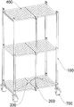
Referring to fig. 1-2, an automatic folding and moving frame includes a frame body 100 and a plurality of folding plates 400 for maintaining an unfolded state after the frame body 100 is unfolded, the folding plates 400 are sequentially disposed in the frame body 100 from top to bottom, a middle rod 200 is disposed on a left-right boundary line of a front end of the frame body 100, an air push rod 300 is disposed on one side of the middle rod 200, and the air push rod 300 drives the frame body 100 to fold or unfold through the middle rod 200.
In this embodiment, the folding plate 400 is connected to the left and right sides of the frame body 100, so that the folding plate 400 can drive the left and right sides of the frame body 100 to move relatively when being folded or unfolded; through setting up middle pole 200, and every folding plate 400 is equal can folding joint middle pole 200, drives folding plate 400 through middle pole 200 and folds or expand the operation, then drives the left and right sides of support body 100 through folding plate 400 and is close to each other or keep away from, realizes the folding or the operation of expanding of support body 100.
Specifically, when the frame body 100 is in the unfolded state, the middle rod 200 is lifted, and the folding plate 400 is folded upwards and drives the left side and the right side of the frame body 100 to approach each other, so that the folding operation of the frame body 100 is realized; when the frame body 100 is in the folded state, the middle rod 200 is pulled down, and the folding plate 400 is unfolded downward and drives the left and right sides of the frame body 100 to be away from each other, thereby realizing the unfolding operation of the frame body 100.
In this embodiment, it lifts or drop-down and then drives folding plate 400 and fold or expand to drive in the middle of pole 200 through air push rod 300 drive, realizes folding or the expansion of support body 100, has replaced the staff to operate, realizes automatic folding and expansion, and is easy and simple to handle, and is more firm after folding, and the gap is less, has reduced the risk of tong, and simple structure, and the maintenance is simple and convenient.
Referring to fig. 1-2, in one embodiment, each folding plate 400 includes two fixing plates disposed on the same horizontal plane, the two fixing plates are respectively disposed on the left and right sides of the frame body 100, and adjacent ends of the two fixing plates are rotatably connected to the middle rod 200 through a connecting member.
In this embodiment, each folding plate 400 is configured as two foldable fixing plates, and two groups of fixing plates in each folding plate 400 may be rectangles with the same shape and size, and of course, may also be other shapes and sizes; two sets of fixed plates in each folded sheet 400 are located both sides about support body 100, but only need pass through connecting piece difference rotatable coupling intermediate lever 200 with the adjacent one end of two sets of fixed plates this moment, reach the purpose that intermediate lever 200 can be through driving two sets of fixed plate activities, but the back of the body one end of two sets of fixed plates also is through pivot difference rotatable coupling on support body 100, reach when intermediate lever 200 drives the fixed plate and folds or expand, the purpose that the left and right sides that two sets of fixed plates can drive support body 100 is close to each other or keeps away from.
Specifically, the connecting member may be an object having a connecting function, one end of the connecting member is connected to the fixing plate, and the other end of the connecting member is connected to the middle rod 200 through the rotating shaft.
In one embodiment, there is a gap between the adjacent end surfaces of the two sets of fixing plates.
In this embodiment, a gap is formed between the two sets of fixing plates of each folding plate 400, so that the two sets of fixing plates can be conveniently folded, and the problem that the adjacent ends of the two sets of fixing plates are blocked due to the fact that the adjacent ends of the two sets of fixing plates are too close to each other and no moving space is available in the folding process is avoided.
In one embodiment, the adjacent end surfaces of the two sets of fixing plates abut against each other, the base angle of one end surface adjacent to the two sets of fixing plates is set to be an arc angle, and the vertex angle of one end surface adjacent to the two sets of fixing plates is set to be a right angle.
In this embodiment, different from the previous embodiment, the adjacent end surfaces of the two groups of fixing plates of each folding plate 400 are abutted, and the bottom angle of the adjacent end surface of the fixing plate is set to be an arc angle; firstly, the adjacent end surfaces of the two groups of fixed plates of each folding plate 400 are arranged to abut against each other, so that the structure is more compact, and when the folding frame is unfolded, the vertex angle of the adjacent end surface between the two groups of fixed plates can abut against each other and limit the two groups of fixed plates to be continuously folded downwards, so that the effect of stabilizing the frame body 100 is achieved; secondly set the base angle of the adjacent terminal surface of two sets of fixed plates to the arc angle, when the intermediate lever 200 drives the folded sheet 400 folding, two sets of fixed plates are upwards folding, and the arc angle of the adjacent terminal surface of two sets of fixed plates can the butt of each other and roll along with upwards folding this moment, the folding operation of the folded sheet 400 of being convenient for.
Referring to fig. 1-2, in one embodiment, two sets of air push rods 300 are disposed on two sides of the middle rod 200.
In this embodiment, in order to make the stress uniform and increase the service life of the rack body 100 and each component, the air push rods 300 are arranged in two groups and respectively arranged at two sides of the middle rod 200.
Specifically, the two sets of air push rods 300 may be symmetrically arranged with the middle rod 200 as a symmetry axis, and the two sets of air push rods 300 perform pushing or retracting operations simultaneously; or arranged in a straight line, only when one group of the air push rods 300 pushes, the other group of the air push rods 300 contracts.
Of course, the air push rod 300 can be arranged in other directions as long as the driving of the middle rod 200 to lift up or pull down can be realized.
Referring to fig. 1-2, in an embodiment, a driving end of the air pushing rod 300 is connected to the middle rod 200, the other end of the air pushing rod 300 is connected to the frame body 100, and the air pushing rod 300 is disposed obliquely.
In this embodiment, the driving end of the air pushing rod 300 is connected to the middle rod 200, the other end of the air pushing rod is rotatably connected to the frame body 100 and is disposed in an inclined manner, the inclined direction is the driving end, when the middle rod 200 needs to be driven to lift, the air pushing rod 300 only needs to push the middle rod 200 to lift, and the folding operation of the frame body 100 can be realized; when the intermediate rod 200 needs to be driven to be pulled down, the intermediate rod 200 is pulled to be pressed down through the air push rod 300, and the unfolding operation of the rack body 100 can be realized.
Of course, the inclined direction may be the driving end is downward, or the driving end is connected to the frame body 100, and the other end is connected to the middle rod 200, as long as the driving of the middle rod 200 to lift up or pull down is achieved.
Referring to fig. 1-2, in one embodiment, the frame body 100 includes four groups of support bars in a rectangular distribution.
In this embodiment, through setting the support body 100 to four groups of support strips that are the rectangular distribution, simple structure conveniently reforms transform the support body 100 and add and put the thing basket.
Specifically, the two sets of fixing plates of each folding plate 400 are rotatably connected to the supporting bars at the left and right sides, respectively, at the ends thereof away from each other.
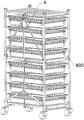
Referring to fig. 5, in an embodiment, a plurality of opposite basket supporting rods 110 are disposed on the frame body 100, and each pair of basket supporting rods 110 is disposed at left and right sides of the frame body 100.
In this embodiment, in order to place more baskets in the unfolded rack 100, a basket support rod 110 is disposed between two sets of support strips on one side of the rack 100, and another basket support rod 110 is disposed between two sets of support strips on the other side to support both ends of the basket.
Referring to fig. 1-2, in one embodiment, a pulley 700 is disposed at the bottom of the frame body 100.
In this embodiment, the pulley 700 is disposed at the bottom of the frame body 100, and a pulley 700 is disposed at the bottom of each supporting bar, so that the frame body 100 is convenient to move.
In one embodiment, a braking device is provided on the pulley 700.
In this embodiment, the sliding of the frame 100 when it is parked is prevented by providing a braking means on the pulley 700.
Specifically, the braking device mentioned in this embodiment may be any commercially available device with a braking function, and may be specifically selected according to the actual application.
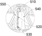
Referring to fig. 5, in an embodiment, the middle rod 200 is provided with a locking operation handle 500 for locking the frame body 100 and keeping the frame body 100 in the unfolded or folded state;
the locking operation handle 500 includes a handle 550, a connecting rod 560 rotatably connected between the handle 550 and the frame body 100, and a locking device disposed on the handle 550, wherein the handle 550 is slidably sleeved on the middle rod 200, and the handle 550 is locked on the middle rod 200 by the locking device.
In this embodiment, by providing the locking operation handle 500, when the frame body 100 is in the folded or unfolded state, the frame body 100 can be maintained in the current state, so as to avoid the instability of the frame body 100 caused by the misoperation.
Specifically, the grab handle 550 is sleeved on the middle rod 200, the connecting rods 560 are arranged on two sides of the grab handle 550, the connecting rods 560 are connected with the grab handle 550 and the frame body 100, so that when the frame body is folded or unfolded, the grab handle 550 can slide up and down along with the approaching or the keeping away of the left and right sides of the frame body 100, and then the frame body 100 is folded or unfolded, and the grab handle 550 is locked on the middle rod 200 through the locking device, so that the sliding of the grab handle 550 is avoided, the frame body 100 is kept in a folded or unfolded state at the moment, and the state cannot be changed randomly, and misoperation is avoided.
Specifically, the handle 550 is slidably sleeved on the middle rod 200 through the slider 540, the handle 550 is disposed on the slider 540, the connecting rods 560 are disposed on two sides of the slider 540, the connecting rods 560 simultaneously rotate to connect the slider 540 and the frame body 100, and the slider 540 is provided with a locking device for locking the frame body 100 to limit relative sliding between the middle rod 200 and the slider 540, and since the slider 540 is connected to the frame body 100 through the connecting rods 560, relative movement between the middle rod 200 and the frame body 100 is limited.
When the frame body 100 needs to be folded, the folding plate 400 is folded upwards and drives the left side and the right side of the frame body 100 to approach each other by lifting the middle rod 200, so that the folding operation of the frame body 100 is realized; when the frame body 100 needs to be unfolded, the folding plate 400 is unfolded downwards and drives the left side and the right side of the frame body 100 to be away from each other through the lower middle rod 200, so that the unfolding operation of the frame body 100 is realized.
Referring to fig. 3-5, in an embodiment, the middle rod 200 is provided with a through hole 210, and the locking device includes a pin hole provided in the handle 550 and a pin 510 inserted into the through hole 210 through the pin hole.
In this embodiment, the locking device includes two latch holes and two latches 510, the latches 510 can be inserted into the through holes 210 through the latch holes, the two through holes 210 are generally disposed at positions of the middle rod 200 corresponding to the latch holes on the handle 550 when being fully folded or unfolded, the latch holes are aligned with the through holes 210, and at this time, the latches 510 can be inserted into the through holes 210 through the latch holes to fix the handle 550.
Specifically, the latch hole is provided on the slider 540.
Referring to fig. 5, in one embodiment, two sets of through holes 210 are provided and are respectively disposed corresponding to the positions of the latch holes when the frame body 100 is unfolded or folded.
In this embodiment, the analysis of the previous embodiment is specifically considered, and is not described herein again.
Of course, there may be a plurality of through holes 210, which do not necessarily correspond to the completely folded or unfolded state, and may be in any state between the two states.
Referring to fig. 5, in one embodiment, two sets of connecting rods 560 are symmetrically disposed.
In this embodiment, by arranging the connecting rods 560 in two sets and symmetrically, it is more stable when the handle 550 is slid.
Referring to fig. 4, in an embodiment, a resilient piece 520 is disposed in the handle 550, and the side of the resilient piece 520 facing the middle rod 200 is connected to the plug 510.
In this embodiment, the elastic fastening sheet 520 is disposed in the grip 550, the elastic fastening sheet 520 is vertically disposed, when the grip 550 is held by a hand, the plug 510 is driven away from the through hole 210, at this time, the state of the rack 100 can be changed by operating the middle rod 200, after the elastic fastening sheet 520 is released, the plug 510 rebounds back to the plug hole under the elastic action and abuts against the middle rod 200, and if the middle rod 200 has the through hole 210, the plug 510 is inserted into the through hole 210 again.
Referring to fig. 4, in one embodiment, one end of the resilient piece 520 is connected to one end of the handle 550 near the pin hole, the other end of the handle 550 is provided with the guide shaft 530, and the other end of the resilient piece 520 is folded back around the guide shaft 530 and connected to the handle 550.
In this embodiment, the plug 510 is asymmetrically disposed at one end of the handle 550, and the installation length of the elastic clamping piece 520 is increased at the other end of the handle 550 through the guide shaft 530, so that when the handle 550 is gripped, the elastic displacement after the elastic clamping piece 520 is gripped is greater, and the plug 510 is prevented from not completely exiting the through hole 210 due to insufficient displacement, and the folding or unfolding of the frame body 100 is prevented from being affected.
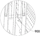
Referring to fig. 5 and 7-8, in one embodiment, two sets of fixing plates of each folding plate 400 are symmetrically provided with a plurality of magnets 900.
In this embodiment, through setting up magnet 900 for after folding, the fifty percent discount of adjacent two sets of fixed plates makes magnet 900 that sets up on the fixed plate attract each other and fix the fixed plate, and then keeps support body 100 in fold condition, and support body 100 after folding is seamless, can prevent the tong, more firm after folding.
Specifically, the magnet 900 has no specific setting requirement and can be selected according to the actual situation.
Referring to fig. 5, in one embodiment, the magnet 900 is a strip and is disposed at the bottom of the fixing plate in the longitudinal direction.
In this embodiment, the magnet 900 is disposed in a long bar shape and at the bottom of the fixing plate which is folded and close to each other, so that the use of the magnet 900 is saved.
Referring to fig. 5-6, in one embodiment, the two sets of fixing plates are provided with vertical connecting rods 800 at the corners thereof away from the two ends thereof for connecting the fixing plates and the frame body 100.
In this embodiment, the vertical link 800 is provided for increasing the stability of the rack body 100 when it is unfolded, and in particular, the middle of the vertical link 800 is bent at a right angle, one end of the vertical link 800 is rotatably connected to the rack body 100 through a rotation shaft, and the other end of the vertical link 800 is connected to the fixing plate.
While the utility model has been described with reference to specific embodiments, it will be understood by those skilled in the art that various changes in form and details may be made therein without departing from the spirit and scope of the utility model as defined by the appended claims. Therefore, the protection scope of the present invention shall be subject to the protection scope of the claims.
Claims (10)
1. The utility model provides an automatic folding removal frame, its characterized in that includes support body (100) and is used for support body (100) expand a plurality of folded sheets (400) of back maintenance expansion state, a plurality of folded sheets (400) from last to set gradually under to in support body (100), be provided with intermediate lever (200) on the boundary line about support body (100) front end, intermediate lever (200) one side sets up air push rod (300), air push rod (300) pass through intermediate lever (200) drive support body (100) are folding or expand.
2. The automatic folding mobile rack of claim 1, characterized in that: each folding plate (400) comprises two groups of fixing plates arranged on the same horizontal plane, the two groups of fixing plates are respectively arranged on the left side and the right side of the frame body (100), and the adjacent ends of the two groups of fixing plates are rotatably connected with the middle rod (200) through connecting pieces.
3. The automatic folding mobile frame of claim 2, characterized in that: and a gap is formed between the adjacent end surfaces of the two groups of fixing plates.
4. The automatic folding mobile frame of claim 2, characterized in that: the adjacent end surfaces of the two groups of fixed plates are abutted, the base angles of the adjacent end surfaces of the two groups of fixed plates are arranged into arc angles, and the vertex angles of the adjacent end surfaces of the two groups of fixed plates are arranged into right angles.
5. The automatic folding mobile frame of claim 1, characterized in that: the air push rods (300) are provided with two groups and are respectively arranged on two sides of the middle rod (200).
6. The automatic folding mobile frame according to any one of claims 1 to 5, characterized in that: the driving end of the air push rod (300) is connected with the middle rod (200), the other end of the air push rod (300) is connected with the frame body (100), and the air push rod (300) is obliquely arranged.
7. The automatic folding mobile frame according to any one of claims 1 to 5, characterized in that: the rack body (100) comprises four groups of support bars which are distributed in a rectangular shape.
8. The automatic folding mobile rack of claim 2, characterized in that: and a plurality of magnets (900) are symmetrically arranged on the two groups of fixing plates.
9. The automatic folding mobile frame of claim 8, characterized in that: the magnet (900) is long-strip-shaped and is longitudinally arranged at the bottom of the fixing plate.
10. The automatic folding mobile rack of claim 8, characterized in that: and the corner parts of the two groups of fixing plates, which are deviated from the two ends, are provided with vertical connecting rods (800) for connecting the fixing plates with the frame body (100).
Priority Applications (1)
| Application Number | Priority Date | Filing Date | Title |
|---|---|---|---|
| CN202122198934.9U CN216776481U (en) | 2021-09-10 | 2021-09-10 | Automatic folding removal frame |
Applications Claiming Priority (1)
| Application Number | Priority Date | Filing Date | Title |
|---|---|---|---|
| CN202122198934.9U CN216776481U (en) | 2021-09-10 | 2021-09-10 | Automatic folding removal frame |
Publications (1)
| Publication Number | Publication Date |
|---|---|
| CN216776481U true CN216776481U (en) | 2022-06-21 |
Family
ID=81997931
Family Applications (1)
| Application Number | Title | Priority Date | Filing Date |
|---|---|---|---|
| CN202122198934.9U Active CN216776481U (en) | 2021-09-10 | 2021-09-10 | Automatic folding removal frame |
Country Status (1)
| Country | Link |
|---|---|
| CN (1) | CN216776481U (en) |
-
2021
- 2021-09-10 CN CN202122198934.9U patent/CN216776481U/en active Active
Similar Documents
| Publication | Publication Date | Title |
|---|---|---|
| US11457728B2 (en) | Foldable table bench | |
| WO2013000149A1 (en) | Table legs folding structure | |
| TWI546488B (en) | Collapsible stand | |
| CN216776481U (en) | Automatic folding removal frame | |
| US20020109441A1 (en) | Folding collapsible clothes cabinet | |
| CN216534381U (en) | Medical folding storing frame capable of locking | |
| CN214623949U (en) | Drawing show shelf is used in machinery teaching convenient to adjust | |
| CN213406600U (en) | Folding stretcher with vertical structure | |
| TWI393617B (en) | A folding stand | |
| CN210447487U (en) | Obstetrical department is with folding nursing car | |
| CN220315033U (en) | Folding trolley frame body with single side open | |
| CN220165668U (en) | Safe and reliable bridge crane | |
| CN208006794U (en) | A kind of detachable Mother-infant nursing device of seat integrated form | |
| CN202128053U (en) | Table leg folding structure | |
| CN219700352U (en) | Quick-dismounting ultra-low nursing bed | |
| CN111483680A (en) | Portable book packaging and displaying rack | |
| CN109910972A (en) | A kind of transport cage vehicle | |
| CN201324019Y (en) | Foldable dining car | |
| CN219069684U (en) | Folding table | |
| CN210355122U (en) | Foldable stretcher special for emergency department | |
| CN217603789U (en) | Wall-mounted fixing device for flat-panel display | |
| CN213999445U (en) | Steel rack convenient to dismantle | |
| CN210946156U (en) | Anti-falling clothes hanger | |
| CN213786544U (en) | A portable demonstration frame for economy and trade | |
| CN217048694U (en) | Detachable and easy-to-store cart |
Legal Events
| Date | Code | Title | Description |
|---|---|---|---|
| GR01 | Patent grant | ||
| GR01 | Patent grant |