CN216773230U - High temperature resistant power chip - Google Patents
High temperature resistant power chip Download PDFInfo
- Publication number
- CN216773230U CN216773230U CN202123147429.8U CN202123147429U CN216773230U CN 216773230 U CN216773230 U CN 216773230U CN 202123147429 U CN202123147429 U CN 202123147429U CN 216773230 U CN216773230 U CN 216773230U
- Authority
- CN
- China
- Prior art keywords
- heat
- explosion
- chip
- proof
- proof shell
- Prior art date
- Legal status (The legal status is an assumption and is not a legal conclusion. Google has not performed a legal analysis and makes no representation as to the accuracy of the status listed.)
- Active
Links
Images

Abstract
The utility model discloses a high-temperature-resistant power supply chip, which comprises an explosion-proof shell, wherein a chip is arranged in the middle of an inner cavity of the explosion-proof shell, the upper surface of the chip is provided with a heat conducting component, the upper surface of the heat conducting component is provided with a heat radiating component extending to the upper part of the explosion-proof shell, the heat dissipation assembly is fixedly connected with the explosion-proof shell, and the two sides of the explosion-proof shell are respectively provided with an air inlet and an air outlet for carrying out air convection on the interior of the explosion-proof shell, because the heat insulation board is a glass fiber board, the heat insulation and flame retardant performance is good, the safety of the chip during the whole operation can be improved through the arrangement of the explosion-proof ceramic board, and the high temperature resistance of the power chip main body during the operation is enhanced.
Description
Technical Field
The utility model relates to the technical field of power chips, in particular to a high-temperature-resistant power chip.
Background
All electronic devices have power supplies, but different systems have different requirements on the power supplies, and in order to exert the best performance of the electronic systems, the most suitable power management mode needs to be selected, so that a power supply chip is required to be installed, and the power supply chip is a chip which plays roles in conversion, distribution, detection and other power management of electric energy in the electronic device system.
However, the conventional power chip is very easy to generate high temperature in the use process, so that electronic components are easily damaged after being subjected to high temperature, the service life is shortened, and meanwhile, the conventional power chip has great potential safety hazard.
SUMMERY OF THE UTILITY MODEL
The present invention is directed to a high temperature resistant power chip to solve the above problems.
In order to achieve the purpose, the utility model provides the following technical scheme:
the utility model provides a high temperature resistance power chip, includes explosion-proof shell, explosion-proof shell inner chamber middle part is provided with the chip, the upper surface of chip is provided with heat-conducting component, heat-conducting component's upper surface is provided with the radiator unit who extends to explosion-proof shell top, just radiator unit and explosion-proof shell fixed connection, explosion-proof shell's both sides are provided with air intake and air outlet that are used for carrying out the air convection to explosion-proof shell inside respectively.
As a further scheme of the utility model: the explosion-proof shell is formed by compounding the heat-insulating plate and the explosion-proof ceramic plate, when the temperature of the outer side of the installation part of the explosion-proof shell is higher, the heat-insulating plate is a glass fiber plate, so that the explosion-proof shell has good heat-insulating flame-retardant performance, the safety of the whole operation of a chip can be improved by setting the explosion-proof ceramic plate, and the high-temperature resistance of the power chip main body in operation is enhanced.
As a still further scheme of the utility model: the explosion-proof housing is a frame structure with an opening at the top end, the two sides inside the explosion-proof housing are provided with partition plates, and the partition plates divide the interior of the explosion-proof housing into two fixing openings and a mounting groove for mounting a chip.
As a still further scheme of the utility model: the heat conduction assembly comprises a first heat conduction plate arranged on the upper surface of the chip, the upper surface of the first heat conduction plate is provided with second heat conduction plates distributed at equal intervals, the second heat conduction plates are of a strip-shaped structure and are adjacent to each other by every two, an air flow channel is formed between the second heat conduction plates, and heat generated when the chip runs can be upwards conducted to the second heat conduction plates through the arrangement of the first heat conduction plates, so that the second heat conduction plates conduct the heat to the heat dissipation assembly to dissipate the heat quickly, and under the action of the air flow channel, when external air flow enters the explosion-proof shell through the air inlet and is discharged through the air outlet, partial heat on the second heat conduction plates and the first heat conduction plates can be taken away, so that the heat dissipation effect of the power chip is enhanced.
As a still further scheme of the utility model: the surfaces of the first heat conduction plate and the second heat conduction plate are coated with heat conduction silicone grease, and the surfaces of the first heat conduction plate and the second heat conduction plate are coated with the heat conduction silicone grease, so that the first heat conduction plate and the second heat conduction plate have high heat conductivity, excellent heat conductivity and good electrical insulation.
As a still further scheme of the utility model: the radiating component comprises a radiating fin, the bottom of the radiating fin is provided with a heat conducting fin used for plugging the top end of the explosion-proof shell, a plurality of fixing feet which are distributed at equal intervals are arranged on two sides of the bottom of the heat conducting fin, the fixing feet are fixed in the fixing openings, the heat radiating component is conveniently and fixedly installed through the arrangement of the fixing feet and the heat conducting fin, and meanwhile heat on the second heat conducting plate is quickly radiated through the heat conducting fin to the radiating fin.
As a still further scheme of the utility model: the radiating fin comprises a plurality of V-shaped pieces which are sequentially adjacent from head to tail, two V-shaped airflow channels are formed between every two adjacent V-shaped pieces, the radiating fin is of a wave structure formed by the V-shaped pieces which are sequentially adjacent from head to tail, and under the action of the V-shaped airflow channels, the contact area between the radiating fin and airflow is greatly increased, so that the radiating effect of the radiating fin is greatly increased, and meanwhile, under the action of the V-shaped airflow channels, the quick circulation of the airflow is facilitated, so that the quick volatilization of heat on the radiating fin is facilitated.
Compared with the prior art, the utility model has the beneficial effects that:
1. according to the utility model, the explosion-proof shell is formed by compounding the heat-insulating plate and the explosion-proof ceramic plate, when the temperature of the outer side of the installation part of the explosion-proof shell is higher, the heat-insulating plate is a glass fiber plate, so that the explosion-proof shell has good heat-insulating flame-retardant property, the safety of the whole operation of the chip can be improved by arranging the explosion-proof ceramic plate, and the high-temperature resistance of the power chip main body in operation is enhanced.
2. Through the setting of first heat-conducting plate, can upwards conduct the heat that produces to the second heat-conducting plate when moving the chip, thereby make the second heat-conducting plate conduct the heat and dispel the heat fast to radiator unit on, and under the effect of air current channel, make the external air current pass through the air intake and get into explosion-proof shell inside and when discharging through the air outlet, can take away the partial heat on second heat-conducting plate and the first heat-conducting plate, thereby the radiating effect of this power chip has been strengthened, through the surface coating heat conduction silicone grease at first heat-conducting plate and second heat-conducting plate, make first heat-conducting plate and second heat-conducting plate have high thermal conductivity, splendid thermal conductivity, good electrical insulation nature has simultaneously.
3. Because the fin comprises a plurality of V type pieces that are adjacent end to end in proper order and forms the wave structure to under the effect of V type air runner, improved the area of contact of fin with the air current greatly, thereby improved the radiating effect of fin greatly, simultaneously under the effect of V type air runner, be favorable to the quick circulation of air current, thereby be favorable to the heat on the fin to volatilize fast.
Drawings
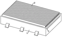
Fig. 1 is a schematic structural diagram of a high temperature resistant power chip.
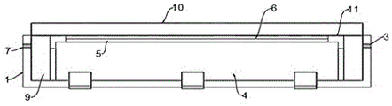
Fig. 2 is an exploded view of a high temperature resistant power chip.
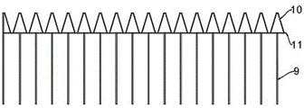
Fig. 3 is a front view of a high temperature resistant power chip.
Fig. 4 is a schematic structural diagram of a heat dissipation assembly in a high temperature resistant power chip.
In the figure: 1. an explosion-proof housing; 2. a heat dissipating component; 3. an air inlet; 4. a chip; 5. a first heat-conducting plate; 6. a second heat-conducting plate; 7. an air outlet; 8. a fixed port; 9. a fixing leg; 10. a heat sink; 11. a heat conductive sheet.
Detailed Description
The technical solutions in the embodiments of the present invention will be clearly and completely described below with reference to the drawings in the embodiments of the present invention, and it is obvious that the described embodiments are only a part of the embodiments of the present invention, and not all of the embodiments. All other embodiments, which can be derived by a person skilled in the art from the embodiments given herein without making any creative effort, shall fall within the protection scope of the present invention.
Referring to fig. 1 to 4, in the embodiment of the utility model, a high-temperature resistant power chip comprises an explosion-proof housing 1, wherein the explosion-proof housing 1 is formed by compounding a heat insulation plate and an explosion-proof ceramic plate, the explosion-proof housing 1 is formed by compounding the heat insulation plate and the explosion-proof ceramic plate, when the temperature of the outer side of the installation part of the explosion-proof housing 1 is higher, the heat insulation plate is a glass fiber plate, so that the high-temperature resistant power chip has good heat insulation and flame retardant properties, the safety of the chip 4 during the whole operation can be improved by the arrangement of the explosion-proof ceramic plate, and the high-temperature resistant performance of the power chip main body during the operation is enhanced;
the heat conduction device is characterized in that an air inlet 3 and an air outlet 7 for conducting air convection to the inside of the explosion-proof shell 1 are respectively arranged on two sides of the explosion-proof shell 1, a chip 4 is arranged in the middle of an inner cavity of the explosion-proof shell 1, the explosion-proof shell 1 is of a frame structure with an opening at the top end, partition plates are respectively arranged on two sides of the inside of the explosion-proof shell 1, the two partition plates divide the inside of the explosion-proof shell 1 into two fixing ports 8 and a mounting groove for mounting the chip 4, a heat conduction assembly is arranged on the upper surface of the chip 4 and comprises a first heat conduction plate 5 arranged on the upper surface of the chip 4, second heat conduction plates 6 distributed at equal intervals are arranged on the upper surface of the first heat conduction plate 5, the second heat conduction plates 6 are of a strip-shaped structure, an air flow channel is formed between every two adjacent second heat conduction plates 6, and heat generated when the chip 4 runs can be upwards conducted to the second heat conduction plates 6 through the arrangement of the first heat conduction plate 5, therefore, the second heat conduction plate 6 conducts heat to the heat dissipation assembly 2 for rapid heat dissipation, and external airflow enters the explosion-proof shell 1 through the air inlet 3 and is discharged through the air outlet 7 under the action of the airflow channel, partial heat on the second heat conduction plate 6 and the first heat conduction plate 5 can be taken away, so that the heat dissipation effect of the power supply chip is enhanced, the surfaces of the first heat conduction plate 5 and the second heat conduction plate 6 are coated with heat conduction silicone grease, and the surfaces of the first heat conduction plate 5 and the second heat conduction plate 6 are coated with the heat conduction silicone grease, so that the first heat conduction plate 5 and the second heat conduction plate have high heat conductivity, excellent heat conductivity and good electrical insulation;
the upper surface of the heat conducting component is provided with a heat radiating component 2 extending to the upper part of the explosion-proof shell 1, the heat radiating component 2 is fixedly connected with the explosion-proof shell 1, the heat radiating component 2 comprises a heat radiating fin 10, the bottom of the heat radiating fin 10 is provided with a heat conducting fin 11 for plugging the top end of the explosion-proof shell 1, two sides of the bottom of the heat conducting fin 11 are provided with a plurality of fixing pins 9 distributed at equal intervals, the fixing pins 9 are fixed in a fixing opening 8, the heat radiating component 2 is conveniently and fixedly installed through the arrangement of the fixing pins 9 and the heat conducting fin 11, meanwhile, heat on the second heat conducting plate 6 is conducted onto the heat radiating fin 10 through the heat conducting fin 11 for rapid heat radiation, the heat radiating fin 10 is composed of a plurality of V-shaped fins which are sequentially adjacent from head to tail, two V-shaped airflow channels are formed between every two adjacent V-shaped fins, and the heat radiating fin 10 is composed of a plurality of V-shaped fins which are sequentially adjacent from head to tail to form a wave structure, and under the effect of V type air current channel, has greatly improved the area of contact of fin 10 with the air current to greatly improved the radiating effect of fin 10, simultaneously under the effect of V type air current channel, be favorable to the fast circulation of air current, thereby be favorable to the heat on the fin 10 to volatilize fast.
The working principle of the utility model is as follows:
when the anti-explosion shell is used, the integral device and an external circuit board are fixedly installed by combining the arranged outer pins with auxiliary materials, the anti-explosion shell 1 is formed by compounding a heat-insulating plate and an anti-explosion ceramic plate, when the temperature of the outer side of the installation part of the anti-explosion shell 1 is higher, the heat-insulating plate is a glass fiber plate, so that the anti-explosion shell has good heat-insulating and flame-retardant properties, the safety of the chip 4 in integral operation can be improved by arranging the anti-explosion ceramic plate, the high-temperature resistance of the power chip main body in operation is enhanced, heat generated in operation of the chip 4 can be upwards conducted onto the second heat-conducting plate 6 by arranging the first heat-conducting plate 5, so that the second heat-conducting plate 6 conducts the heat onto the heat-radiating component 2 for rapid heat radiation, and when external airflow enters the interior of the anti-explosion shell 1 through the air inlet 3 and is discharged through the air outlet 7 under the action of the airflow channel, partial heat on second heat-conducting plate 6 and the first heat-conducting plate 5 can be taken away, thereby the radiating effect of the power chip is strengthened, through the setting of fixed foot 9 and conducting strip 11, be convenient for carry out fixed mounting to radiator unit 2, heat on the second heat-conducting plate 6 is conducted to the fin 10 through conducting strip 11 and is dispeled the heat fast simultaneously, because fin 10 comprises a plurality of V type pieces that are adjacent in proper order from beginning to end and form wave structure, and under the effect of V type air runner, the area of contact of fin 10 with the air current has been improved greatly, thereby the radiating effect of fin 10 is improved greatly, simultaneously under the effect of V type air runner, be favorable to the rapid circulation of air current, thereby be favorable to the heat on fin 10 to volatilize fast.
The above description is only for the preferred embodiment of the present invention, but the scope of the present invention is not limited thereto, and any person skilled in the art should be considered to be within the technical scope of the present invention, and equivalent alternatives or modifications according to the technical solution of the present invention and the inventive concept thereof should be covered by the scope of the present invention.
Claims (7)
1. The utility model provides a high temperature resistance power chip, includes explosion-proof shell (1), its characterized in that, explosion-proof shell (1) inner chamber middle part is provided with chip (4), the upper surface of chip (4) is provided with heat-conducting component, heat-conducting component's upper surface is provided with radiator unit (2) that extend to explosion-proof shell (1) top, just radiator unit (2) and explosion-proof shell (1) fixed connection, the both sides of explosion-proof shell (1) are provided with air intake (3) and air outlet (7) that are used for carrying out the air convection to explosion-proof shell (1) inside respectively.
2. The high-temperature-resistant power chip as claimed in claim 1, wherein the explosion-proof housing (1) is formed by compounding an insulating plate and an explosion-proof ceramic plate.
3. The high-temperature-resistant power chip as claimed in claim 1, wherein the explosion-proof housing (1) is a frame structure with an open top end, and two partitions are arranged on two sides of the inside of the explosion-proof housing (1) and divide the inside of the explosion-proof housing (1) into two fixing ports (8) and a mounting groove for mounting the chip (4).
4. The high-temperature-resistant power chip is characterized in that the heat-conducting component comprises a first heat-conducting plate (5) arranged on the upper surface of the chip (4), the upper surface of the first heat-conducting plate (5) is provided with second heat-conducting plates (6) distributed at equal intervals, the second heat-conducting plates (6) are in strip-shaped structures, and a gas flow channel is formed between every two adjacent second heat-conducting plates (6).
5. The high-temperature-resistant power chip is characterized in that the surfaces of the first heat-conducting plate (5) and the second heat-conducting plate (6) are coated with heat-conducting silicone grease.
6. The high-temperature-resistant power chip as claimed in claim 3, wherein the heat dissipation assembly (2) comprises a heat dissipation fin (10), a heat conduction fin (11) for blocking the top end of the explosion-proof housing (1) is arranged at the bottom of the heat dissipation fin (10), a plurality of fixing pins (9) distributed at equal intervals are arranged on two sides of the bottom of the heat conduction fin (11), and the fixing pins (9) are fixed in the fixing openings (8).
7. The high-temperature-resistant power chip is characterized in that the heat sink (10) is composed of a plurality of V-shaped fins which are adjacent end to end, and two V-shaped air channels are formed between every two adjacent V-shaped fins.
Priority Applications (1)
| Application Number | Priority Date | Filing Date | Title |
|---|---|---|---|
| CN202123147429.8U CN216773230U (en) | 2021-12-15 | 2021-12-15 | High temperature resistant power chip |
Applications Claiming Priority (1)
| Application Number | Priority Date | Filing Date | Title |
|---|---|---|---|
| CN202123147429.8U CN216773230U (en) | 2021-12-15 | 2021-12-15 | High temperature resistant power chip |
Publications (1)
| Publication Number | Publication Date |
|---|---|
| CN216773230U true CN216773230U (en) | 2022-06-17 |
Family
ID=81967229
Family Applications (1)
| Application Number | Title | Priority Date | Filing Date |
|---|---|---|---|
| CN202123147429.8U Active CN216773230U (en) | 2021-12-15 | 2021-12-15 | High temperature resistant power chip |
Country Status (1)
| Country | Link |
|---|---|
| CN (1) | CN216773230U (en) |
-
2021
- 2021-12-15 CN CN202123147429.8U patent/CN216773230U/en active Active
Similar Documents
| Publication | Publication Date | Title |
|---|---|---|
| CN211530440U (en) | Heat dissipation type safety protection switch board | |
| CN211502460U (en) | Lamp set | |
| CN216773230U (en) | High temperature resistant power chip | |
| CN111587046B (en) | Heat dissipation device | |
| CN210309967U (en) | Terminal cooling mechanism and rifle that charges | |
| CN215578213U (en) | Capacitor case with high heat dissipation effect | |
| CN213125826U (en) | High-efficient heat dissipation type converter | |
| CN209982994U (en) | Communication equipment and optical module with heat dissipation structure | |
| CN112769050A (en) | High-efficient heat dissipation high-voltage board | |
| CN208445922U (en) | A kind of heat dissipation of sealing air flue formula power amplifier and power supply unit | |
| CN219322844U (en) | Control box and electric appliance | |
| CN213880397U (en) | Circuit board that possesses fire prevention function | |
| CN217563985U (en) | Heat dissipation assembly and energy storage power supply | |
| CN218040691U (en) | Fire-resistant intensive bus duct | |
| CN218602539U (en) | Heat abstractor, power supply unit and integral type energy storage equipment | |
| CN217825745U (en) | Electrical assembly with heat dissipation component | |
| CN215735544U (en) | Integrated circuit substrate for unmanned aerial vehicle | |
| CN216532433U (en) | Main control box | |
| CN216450011U (en) | Heat radiation structure and server | |
| CN209840033U (en) | Heat conduction shell structure of LED power | |
| CN216626504U (en) | Integrated imaging circuit board | |
| CN220439606U (en) | Novel coupler | |
| CN216852902U (en) | Natural convection type radiator for radiating heat of multiple heat sources | |
| CN219756296U (en) | Lamp heat dissipation device and floodlight | |
| CN220383422U (en) | Radiator and electronic equipment |
Legal Events
| Date | Code | Title | Description |
|---|---|---|---|
| GR01 | Patent grant | ||
| GR01 | Patent grant |