CN216769667U - Self-searching negative pressure ventilator - Google Patents
Self-searching negative pressure ventilator Download PDFInfo
- Publication number
- CN216769667U CN216769667U CN202220137035.XU CN202220137035U CN216769667U CN 216769667 U CN216769667 U CN 216769667U CN 202220137035 U CN202220137035 U CN 202220137035U CN 216769667 U CN216769667 U CN 216769667U
- Authority
- CN
- China
- Prior art keywords
- shaped
- sliding baffle
- umbrella
- arc
- negative pressure
- Prior art date
- Legal status (The legal status is an assumption and is not a legal conclusion. Google has not performed a legal analysis and makes no representation as to the accuracy of the status listed.)
- Active
Links
Images


Landscapes
- Ventilation (AREA)
Abstract
The utility model discloses a self-searching negative pressure ventilator which can be used for parts needing long-term air exhaust, such as an air outlet at the top of a building, a tunnel air exhaust well, a mine air outlet and the like, and comprises an umbrella-shaped hood, arc-shaped shutters and a sliding baffle plate; the sliding baffle is in a round tube shape, and a ventilation opening is formed in the side wall of the sliding baffle; the arc-shaped shutter is arranged in the sliding baffle; the arc-shaped shutter is connected with the inner ring of the bearing, and the sliding baffle is connected with the outer ring of the bearing; the umbrella-shaped hood is fixedly arranged at the top of the sliding baffle, and the guide plate is fixedly arranged on the umbrella-shaped hood. The utility model has simple structure, when wind current exists outdoors, the fan can be connected with the umbrella-shaped blast cap and the sliding baffle by utilizing the guiding function of the guide blades to partially block the incoming wind of the ventilator in any horizontal direction, increase the exposed area of the ventilator in the negative pressure areas at the top, the side and the back, fully utilize the negative pressure to discharge the air in the building outdoors, and have reliable work.
Description
Technical Field
The utility model relates to an energy-saving ventilation device, in particular to a self-searching negative pressure ventilator. The air-permeable brick can be used for parts needing long-term air exhaust, such as air outlets at the top of a building, tunnel air exhaust shafts, mine air outlets and the like.
Background
The natural ventilation is to improve the huge ventilation volume of the product, improve the air quality inside the artificial structure, reduce the occurrence of air-related diseases, simultaneously does not consume any artificial energy, and is widely used in the fields of buildings, tunnels, mines and the like. On one hand, certain rooms in a building, such as toilets, bathrooms, kitchens and the like, need continuous air exhaust effects, and on the other hand, scenes, such as tunnels, mines and the like, also need continuous air exhaust effects, but the energy consumption of mechanical exhaust fans is huge, and how to reduce the energy consumption becomes an important research direction.
The natural ventilation is mainly driven by a hot-pressing ventilation principle and a wind pressure ventilation principle, wherein the latter drives the air flow to enter and exit by utilizing the pressure difference between the inside and the outside of a structure formed by the motion of the near-earth atmosphere, but the wind pressure ventilation has high instability due to the continuous change of outdoor wind direction, and the air supply, exhaust and ventilation quantity is often difficult to control, so that the design requirement cannot be met. In scenes such as buildings, tunnels, mines and the like, continuous air exhaust effect is expected in many scenes. Therefore, how to obtain a continuous air exhaust effect on the premise of no power becomes the key point of the technology.
Disclosure of Invention
In order to solve the technical problems, the utility model provides the self-searching negative pressure ventilator which is simple in structure and reliable in work, and the windward side of the ventilator can be always in a shielding state through the guide blades according to the aerodynamic principle; the upper part, the left side surface, the right side surface and the leeward side surface are always in an open state to keep negative pressure, so that a suction effect is generated, and a continuous air exhaust effect is achieved.
The technical scheme for solving the problems is as follows: a self-seeking negative pressure ventilator comprises an umbrella-shaped hood, an arc-shaped shutter and a sliding baffle; the sliding baffle is in a circular tube shape, and the side wall of the sliding baffle is provided with a vent; the arc-shaped shutter is arranged in the sliding baffle; the arc-shaped shutter is connected with the inner ring of the bearing, and the sliding baffle is connected with the outer ring of the bearing; the umbrella-shaped hood is fixedly arranged at the top of the sliding baffle, and the guide plate is fixedly arranged on the umbrella-shaped hood.
Furthermore, two cross-shaped brackets are fixedly arranged in the arc-shaped shutter, and the centers of the two cross-shaped brackets support the rotating shaft through bearings; the upper end of the rotating shaft is fixedly connected with the center of the umbrella-shaped blast cap.
Furthermore, the ventilation opening of the sliding baffle is rectangular, and the guide plate is perpendicular to the ventilation opening of the sliding baffle.
Furthermore, the surfaces of the umbrella-shaped blast cap, the polygonal guide plate, the sliding baffle, the arc shutter and the bearing are coated with anticorrosive coatings.
Compared with the prior art, the utility model has the beneficial effects that:
1. the guide plate is connected with the umbrella-shaped hood and the sliding baffle, and the sliding baffle can always block forward wind by utilizing the negative pressure effect when wind current exists outdoors, so that the equipment is self-directional, the operation is reliable, and meanwhile, the equipment does not use redundant energy supply, and is green and low-carbon.
2. The utility model is provided with the sliding baffle which can surround one half of the arc-shaped shutter, and the self-direction-finding function of the utility model can block the forward wind, increase the exposed area in the negative pressure area and increase the air discharge capacity by utilizing the pressure difference.
3. The utility model is provided with the arc-shaped shutter, increases the contact area with the negative pressure area and utilizes the pressure difference effect to the maximum extent. The shape of the arc-shaped shutter can increase the contact area with the negative pressure area, and simultaneously, the rain-proof effect is achieved by blocking rainwater.
Drawings
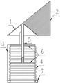
Fig. 1 is a front view of the present invention.
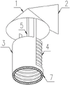
Fig. 2 is a perspective view of a first viewing angle of the present invention.
Fig. 3 is a perspective view of the present invention from a second perspective.
Fig. 4 is a cross-sectional view of the present invention.
Detailed Description
The utility model is further described below with reference to the accompanying drawings.
As shown in fig. 1-4, the utility model comprises an umbrella-shaped hood 1, a guide plate 2, a sliding baffle 3, an arc-shaped louver 4, a rotating shaft 5, a cross-shaped bracket 6 and a bearing 7. The sliding baffle 3 and the arc-shaped shutter 4 are in a circular tube shape, and a rectangular ventilation opening is formed in the side wall of the sliding baffle 3. The arc-shaped shutter 4 is arranged in the sliding baffle 3; the arc-shaped shutter 4 is connected with the inner ring of the bearing 7, and the sliding baffle 3 is connected with the outer ring of the bearing 7. The umbrella-shaped hood is fixedly arranged at the top of the sliding baffle, and the guide plate 2 is fixedly arranged on the umbrella-shaped hood 1. The guide plate 2 is a polygonal plate-shaped structure, which is perpendicular to the ventilation opening of the slide shutter 3. The top and the middle part of the arc-shaped shutter 3 are respectively and fixedly provided with a cross-shaped bracket 6, and the centers of the two cross-shaped brackets 6 support a rotating shaft 5 through a bearing; the upper end of the rotating shaft 5 is fixedly connected with the center of the umbrella-shaped blast cap 1.
The umbrella-shaped blast cap 1 is arranged at the top of the ventilator and plays a role in shielding rainwater for the utility model. The polygonal guide plate 2 arranged on the umbrella-shaped blast cap 1 can drive the sliding baffle 3 to rotate when wind flows outdoors until the sliding baffle 3 stops positive incoming wind, so that the guide effect is achieved. And the rotating shaft 5 which is embedded with the umbrella-shaped hood 1 plays a role of supporting the umbrella-shaped hood 1. The cross-shaped support 6 arranged in the middle of the rotating shaft 5 and at the top supports the rotating shaft 5, so that the rotating shaft 5 is more stable. The arc-shaped shutter 4 fixes the cross-shaped bracket 6, so that the exposed area of the negative pressure area is increased, and the effect of shielding rainwater is also achieved. The inner ring of the bearing 7 at the bottom of the arc-shaped shutter 4 is connected, the outer ring of the bearing 7 is connected with the sliding baffle 3, and the inner ring is connected with the arc-shaped shutter 4, so that the process of self-direction finding can be finished smoothly. The sliding baffle 3 is connected with the umbrella-shaped hood 1, surrounds the arc-shaped shutter 4, is connected with the outer ring of the bearing 7 at the bottom, plays a role in blocking normal wind, and simultaneously shields rainwater.
The sliding baffle 3 is arranged outside the arc-shaped shutter 4, the upper part of the sliding baffle 3 is connected with the umbrella-shaped hood 1, the lower part of the sliding baffle is connected with the outer ring of the bearing 7, and the polygonal guide plate 2 and the bearing 7 on the umbrella-shaped hood 1 can be used for blocking forward incoming wind all the time, preventing the forward incoming wind from disturbing the air exhaust process of a structure and simultaneously playing a role of shielding rainwater. The surfaces of the umbrella-shaped air cap 1, the polygonal guide plate 2, the sliding baffle 3, the arc-shaped shutter 4 and the bearing 7 are coated with anticorrosive coatings, so that the damage risk is reduced, and the service life is prolonged.
The guide plate 2 of the utility model has the function of enabling the ventilator to change along with the outdoor wind direction, ensuring that the windward side is always in a shielding state, namely enabling the ventilation opening of the sliding baffle 3 to be always on the leeward side. Meanwhile, the upper surface and the leeward surface of the sliding baffle 3 are always in an open state to form continuous negative pressure, so that a suction effect is generated, and a continuous air exhaust effect is achieved.
Claims (4)
1. The utility model provides a seek negative pressure ventilator certainly which characterized in that: comprises an umbrella-shaped hood (1), an arc-shaped shutter (4) and a sliding baffle (3); the sliding baffle (3) is in a circular tube shape, and the side wall of the sliding baffle is provided with a vent; the arc-shaped shutter (4) is arranged in the sliding baffle (3); the arc-shaped shutter (4) is connected with the inner ring of the bearing (7), and the sliding baffle (3) is connected with the outer ring of the bearing (7); the umbrella-shaped blast cap (1) is fixedly arranged at the top of the sliding baffle (3), and the guide plate (2) is fixedly arranged on the umbrella-shaped blast cap (1).
2. The self-searching negative pressure ventilator according to claim 1, wherein: two cross-shaped brackets (6) are fixedly arranged in the arc-shaped shutter (4), and the centers of the two cross-shaped brackets (6) support the rotating shaft (5) through bearings; the upper end of the rotating shaft (5) is fixedly connected with the center of the umbrella-shaped blast cap (1).
3. The self-seeking negative pressure ventilator according to claim 1, wherein: the ventilation opening of the sliding baffle (3) is rectangular, and the guide plate (2) is perpendicular to the ventilation opening of the sliding baffle (3).
4. The self-seeking negative pressure ventilator according to claim 1, wherein: the surfaces of the umbrella-shaped hood (1), the guide plate (2), the sliding baffle (3), the arc-shaped shutter (4) and the bearing (7) are coated with anticorrosive coatings.
Priority Applications (1)
| Application Number | Priority Date | Filing Date | Title |
|---|---|---|---|
| CN202220137035.XU CN216769667U (en) | 2022-01-19 | 2022-01-19 | Self-searching negative pressure ventilator |
Applications Claiming Priority (1)
| Application Number | Priority Date | Filing Date | Title |
|---|---|---|---|
| CN202220137035.XU CN216769667U (en) | 2022-01-19 | 2022-01-19 | Self-searching negative pressure ventilator |
Publications (1)
| Publication Number | Publication Date |
|---|---|
| CN216769667U true CN216769667U (en) | 2022-06-17 |
Family
ID=81978738
Family Applications (1)
| Application Number | Title | Priority Date | Filing Date |
|---|---|---|---|
| CN202220137035.XU Active CN216769667U (en) | 2022-01-19 | 2022-01-19 | Self-searching negative pressure ventilator |
Country Status (1)
| Country | Link |
|---|---|
| CN (1) | CN216769667U (en) |
-
2022
- 2022-01-19 CN CN202220137035.XU patent/CN216769667U/en active Active
Similar Documents
| Publication | Publication Date | Title |
|---|---|---|
| CN211953167U (en) | Building energy-saving ventilation device | |
| CN216769667U (en) | Self-searching negative pressure ventilator | |
| CN203687255U (en) | Air conditioning system combining evaporative cooling, solar energy and ventilator and applied to industrial factory building | |
| CN214619934U (en) | Green building energy-saving equipment that ventilates | |
| CN204418462U (en) | Roof ventilator | |
| CN114322153A (en) | Self-searching negative pressure ventilator | |
| CN211600999U (en) | Intelligent energy-saving air exchange system | |
| CN219550744U (en) | Energy-saving ventilating system for green building | |
| CN211290378U (en) | Environment-friendly solar air conditioner heating and ventilating equipment | |
| CN208431905U (en) | A kind of totally-enclosed coal yard ventilating system | |
| CN215765555U (en) | Ventilator | |
| CN213873132U (en) | Central air conditioning air ducting convenient to maintain | |
| KR100442267B1 (en) | In-door-unit of ceiling type air-conditioner | |
| CN210667605U (en) | Weather-resistant LED display screen assembly | |
| CN209840363U (en) | Ventilation energy-saving equipment of green building | |
| CN212930341U (en) | Energy-saving type ventilation structure of culture room | |
| CN206338875U (en) | The outdoor unit of combined air conditioners | |
| CN112252551A (en) | Outer curtain wall of double-layer curtain wall and curtain wall system | |
| CN213480490U (en) | Special electric fan for night | |
| CN205424823U (en) | Building indoor lighting ventilation unit | |
| CN210035785U (en) | Energy-conserving ventilation unit for building | |
| CN212304764U (en) | SVG controllable formula air cooling system | |
| CN1987231A (en) | Natural environmental protection type house ventilation and air intake device | |
| KR102276683B1 (en) | Air conditioning duct ventilation power generation system in buildings | |
| CN219346707U (en) | High-rise building ventilation structure |
Legal Events
| Date | Code | Title | Description |
|---|---|---|---|
| GR01 | Patent grant | ||
| GR01 | Patent grant |