CN216742910U - Electronic expansion valve - Google Patents
Electronic expansion valve Download PDFInfo
- Publication number
- CN216742910U CN216742910U CN202220249839.9U CN202220249839U CN216742910U CN 216742910 U CN216742910 U CN 216742910U CN 202220249839 U CN202220249839 U CN 202220249839U CN 216742910 U CN216742910 U CN 216742910U
- Authority
- CN
- China
- Prior art keywords
- valve
- small
- channel
- needle
- hole
- Prior art date
- Legal status (The legal status is an assumption and is not a legal conclusion. Google has not performed a legal analysis and makes no representation as to the accuracy of the status listed.)
- Active
Links
Images


Abstract
The utility model provides an electronic expansion valve, comprising: a valve seat member; the valve sleeve is connected with the valve seat component; the valve needle component is arranged in the valve seat component and comprises a main body part and a small valve needle, the main body part is provided with a small valve port, and the small valve needle is movably arranged to adjust the opening degree of the small valve port; the driving part is arranged in the cavities of the valve seat part and the valve sleeve, a rotor cavity is formed in a region between the structure of the driving part in the valve sleeve and the inner wall of the valve sleeve, and the driving part is in driving connection with the small valve needle; and the balance channel is used for communicating the rotor cavity with the small valve port. By adopting the scheme, the rotor cavity and the small valve port are communicated by arranging the balance channel, when the electronic expansion valve works, the pressure of the small valve port and the pressure in the rotor cavity are always kept consistent, the optimal balance effect in the electronic expansion valve is ensured, and the problem of bad valve closing caused by larger pressure difference between the rotor cavity and the small valve port is avoided.
Description
Technical Field
The utility model relates to the technical field of electronic expansion valves, in particular to an electronic expansion valve.
Background
In the past, in various cooling and heating apparatuses such as air conditioners, refrigerators, heat pump water heaters, and the like, an electronic expansion valve is generally used to adjust the flow rate of a fluid. The electronic expansion valve generally comprises a valve seat component, a valve needle component, a driving component, a valve sleeve and the like, wherein a rotor cavity is formed between the valve sleeve and the valve seat component, the valve seat component generally comprises a valve seat and a connecting pipe, a valve port is arranged on the valve seat, and the opening degree of the valve port is adjusted through the movement of the valve needle component to realize circulation control. In the electronic expansion valve in the prior art, a balance channel is not usually arranged between a rotor cavity and a valve port, so that the optimal balance effect cannot be achieved, and the opening and closing effect of the valve port is influenced.
SUMMERY OF THE UTILITY MODEL
The utility model provides an electronic expansion valve, which aims to solve the problem that the interior of the electronic expansion valve in the prior art is difficult to achieve pressure balance.
In order to solve the above problems, the present invention provides an electronic expansion valve, comprising: a valve seat member; the valve sleeve is connected with the valve seat component; the valve needle component is arranged in the valve seat component and comprises a main body part and a small valve needle, the main body part is provided with a small valve port, and the small valve needle is movably arranged to adjust the opening degree of the small valve port; the driving part is arranged in the cavities of the valve seat part and the valve sleeve, a rotor cavity is formed in a region between the structure of the driving part in the valve sleeve and the inner wall of the valve sleeve, and the driving part is in driving connection with the small valve needle; and the balance channel is used for communicating the rotor cavity with the small valve port.
Further, the valve seat component comprises a valve seat ring and a base, and the valve sleeve, the valve seat ring and the base are sequentially connected; the driving part comprises a nut structure and a screw rod assembly, the nut structure is located in the valve sleeve, a rotor cavity is formed in an area between the nut structure and the inner wall of the valve sleeve, the screw rod assembly is in threaded connection with the nut structure, and the screw rod assembly is in driving connection with the small valve needle.
Furthermore, the balance channel comprises a first channel, a second channel, a third channel and a fourth channel which are sequentially communicated, wherein the first channel is located in the nut structure, the second channel is located in the valve seat ring, the third channel is located in the screw rod assembly, and the fourth channel is located in the small valve needle.
Further, the nut structure includes nut main part and connecting plate, and the connecting plate cover is established in the nut main part, and connecting plate and valve seat ring welding, trompil or fluting on the connecting plate form first passageway.
Furthermore, a guide cavity and a first through hole are formed in the valve seat ring, an annular groove is formed in the inner wall of the guide cavity, a part of the main body part is located in the guide cavity, the first through hole is communicated with the annular groove, and a second channel is formed by the first through hole and the annular groove; or the valve seat ring is internally provided with a guide cavity and a first through hole, one part of the main body part is positioned in the guide cavity, and the first through hole forms a second channel.
Furthermore, the screw assembly comprises a screw and a connecting sleeve, the screw is in threaded connection with the nut structure, the screw is in limit fit with the connecting sleeve, the connecting sleeve is connected with the small valve needle, the fourth channel is communicated with a cavity in the connecting sleeve, a second through hole is formed in the side wall of the connecting sleeve, and the second through hole forms a third channel.
Further, the small valve needle comprises a limiting rod and a plugging rod which are connected with each other, the radial size of the limiting rod is larger than that of the plugging rod, the limiting rod is matched with the main body part in an axial stop mode, the plugging rod is used for being matched with the small valve opening, a third through hole is formed in the limiting rod, a fourth through hole is formed in the plugging rod, and a fourth channel is formed by the third through hole and the third through hole.
Further, the side wall of the valve seat component is provided with a flow hole, the main body part is provided with a side hole, and the side hole is positioned on one side of the small valve opening facing the driving component; wherein, under the condition that the small valve opening is opened, the circulation hole, the side opening and the small valve opening are communicated in sequence.
Further, the valve needle component also comprises a first inner sealing ring and a second inner sealing ring, the first inner sealing ring is positioned between the outer wall of the small valve needle and the inner wall of the main body part, and the second inner sealing ring is positioned between the outer wall of the main body part and the inner wall of the valve seat component.
Further, the valve seat component is provided with a large valve port, the large valve port and the small valve port are coaxially arranged, the main body part is movably arranged to open and close the large valve port, and the rotor cavity, the small valve port and the large valve port are communicated through the balance channel.
The technical scheme of the utility model is applied to provide an electronic expansion valve, which comprises: a valve seat member; the valve sleeve is connected with the valve seat component; the valve needle component is arranged in the valve seat component and comprises a main body part and a small valve needle, the main body part is provided with a small valve port, and the small valve needle is movably arranged to adjust the opening degree of the small valve port; the driving part is arranged in the cavities of the valve seat part and the valve sleeve, a rotor cavity is formed in a region between the structure of the driving part in the valve sleeve and the inner wall of the valve sleeve, and the driving part is in driving connection with the small valve needle; and the balance channel is used for communicating the rotor cavity with the small valve port. By adopting the scheme, the rotor cavity and the small valve port are communicated by arranging the balance channel, when the electronic expansion valve works, the pressure of the small valve port and the pressure in the rotor cavity are always kept consistent, the optimal balance effect in the electronic expansion valve is ensured, the upper end and the lower end of the valve needle component are balanced by pressure, and the problem of poor valve closing caused by large pressure difference between the rotor cavity and the small valve port is avoided. In this scheme, the drive unit drives little needle and removes, adjusts the aperture of little valve port through the removal of little needle to flow control's function has been realized.
Drawings
The accompanying drawings, which are incorporated in and constitute a part of this application, illustrate embodiments of the utility model and, together with the description, serve to explain the utility model and not to limit the utility model. In the drawings:
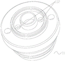
fig. 1 shows a cross-sectional view of an electronic expansion valve provided by an embodiment of the present invention;
FIG. 2 shows a schematic structural view of the nut structure of FIG. 1;
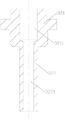
FIG. 3 shows a schematic view of the seat ring of FIG. 1;
FIG. 4 shows a cross-sectional view of the seat ring of FIG. 3;
fig. 5 shows a cross-sectional view of the connection sleeve of fig. 1;
figure 6 shows a cross-sectional view of the small valve needle of figure 1.
Wherein the figures include the following reference numerals:
10. a valve seat member; 11. a valve seat ring; 111. a guide cavity; 1111. an annular groove; 112. a first through hole; 12. a base; 13. a flow-through hole; 14. a large valve port;
20. a valve housing;
30. a valve needle component; 31. a main body portion; 311. a small valve port; 312. side opening; 32. a small valve needle; 321. a limiting rod; 3211. a third through hole; 322. a plugging rod; 3221. a fourth via hole; 33. a first inner seal ring; 34. a second inner seal ring;
40. a drive member; 41. a nut structure; 411. a nut body; 412. a connecting plate; 4121. grooving; 42. a screw assembly; 421. a screw; 422. connecting sleeves; 4221. a second through hole;
50. a rotor cavity;
60. a balancing channel; 61. a first channel; 62. a second channel; 63. a third channel; 64. and a fourth channel.
Detailed Description
The technical solution in the embodiments of the present invention will be clearly and completely described below with reference to the accompanying drawings in the embodiments of the present invention. It is to be understood that the described embodiments are merely exemplary of the utility model, and not restrictive of the full scope of the utility model. The following description of at least one exemplary embodiment is merely illustrative in nature and is in no way intended to limit the utility model, its application, or uses. All other embodiments, which can be derived by a person skilled in the art from the embodiments given herein without making any creative effort, shall fall within the protection scope of the present invention.
As shown in fig. 1 to 6, an embodiment of the present invention provides an electronic expansion valve, including: a valve seat member 10; the valve housing 20, the valve housing 20 and the valve seat part 10 are connected; a needle member 30 disposed in the valve seat member 10, the needle member 30 including a main body portion 31 and a small needle 32, the main body portion 31 having a small valve port 311, the small needle 32 being movably disposed to adjust an opening degree of the small valve port 311; a driving member 40 disposed in the valve seat member 10 and the cavity of the valve housing 20, a region of the driving member 40 between the structure in the valve housing 20 and the inner wall of the valve housing 20 forming a rotor chamber 50, the driving member 40 being in driving connection with the small needle 32; a balance passage 60, the balance passage 60 communicating the rotor chamber 50 and the small valve port 311.
By adopting the scheme, the rotor cavity 50 is communicated with the small valve opening 311 by arranging the balance channel 60, when the electronic expansion valve works, the pressure of the small valve opening 311 and the pressure in the rotor cavity 50 can be kept consistent all the time, and the optimal balance effect in the electronic expansion valve can be ensured, so that the problem of bad valve closing caused by a larger pressure difference between the rotor cavity 50 and the small valve opening 311 is avoided. In this embodiment, the driving member 40 drives the small valve needle 32 to move, and the opening of the small valve port 311 is adjusted by the movement of the small valve needle 32, thereby achieving the function of flow rate adjustment. The electronic expansion valve can be installed in a mounting base or a valve body for use.
Wherein, the valve seat part 10 comprises a valve seat ring 11 and a base 12, and the valve sleeve 20, the valve seat ring 11 and the base 12 are connected in sequence; the driving part 40 includes a nut structure 41 and a screw assembly 42, the nut structure 41 is located in the valve housing 20, the area between the nut structure 41 and the inner wall of the valve housing 20 forms a rotor chamber 50, the screw assembly 42 is in threaded connection with the nut structure 41, and the screw assembly 42 is in driving connection with the small valve needle 32. With the above arrangement, the nut structure 41 is disposed within the valve housing 20 such that the region between the nut structure 41 and the inner wall of the valve housing 20 forms the rotor chamber 50; the screw rod assembly 42 and the nut structure 41 are in threaded connection, and the connection mode is high in movement precision and stable and reliable in operation. In the scheme, the screw assembly 42 is in driving connection with the small valve needle 32 to drive the small valve needle 32 to move, so that the opening degree of the small valve port 311 is adjusted.
Optionally, the electronic expansion valve further comprises a rotor component disposed within the valve housing 20, the rotor component being configured to drive the screw assembly 42 to rotate, and a gap is formed between the rotor component and the inner wall of the valve housing 20.
Further, the balance passage 60 includes a first passage 61, a second passage 62, a third passage 63 and a fourth passage 64 which are communicated in sequence, wherein the first passage 61 is located in the nut structure 41, the second passage 62 is located in the valve seat ring 11, the third passage 63 is located in the screw assembly 42, and the fourth passage 64 is located in the small valve needle 32. The first channel 61 is arranged in the nut structure 41, the second channel 62 is arranged in the valve seat ring 11, the third channel 63 is arranged in the screw rod assembly 42, and the fourth channel 64 is arranged in the small valve needle 32, so that the rotor cavity 50 is communicated with the small valve opening 311 through the balance channel 60, and the problem of poor valve closing caused by large pressure difference between the rotor cavity 50 and the small valve opening 311 is avoided.
The nut structure 41 includes a nut body 411 and a connecting plate 412, the connecting plate 412 is sleeved on the nut body 411, the connecting plate 412 is welded to the valve seat ring 11, and an opening or a slot 4121 in the connecting plate 412 forms the first channel 61. The connecting plate 412 and the valve seat ring 11 are connected in a welding mode, so that the stability and reliability are realized; the openings or slots 4121 in the web 412 each form a first channel 61, thereby providing communication between the rotor chamber 50 and the first channel 61.
In the present embodiment, the valve seat ring 11 has the guide chamber 111 and the first through-hole 112 therein, the inner wall of the guide chamber 111 has the annular groove 1111, a portion of the main body portion 31 is located in the guide chamber 111, the first through-hole 112 communicates with the annular groove 1111, and the first through-hole 112 and the annular groove 1111 form the second passage 62. By providing the guide cavity 111, it is convenient to dispose a part of the main body portion 31 in the guide cavity 111; by communicating the first through hole 112 with the annular groove 1111, since the first passage 61 and the second passage 62 communicate, the pressure in the rotor chamber 50 and the pressure in the annular groove 1111 can be kept the same. Wherein the annular groove 1111 communicates with the third passage 63. Alternatively, the valve seat ring 11 has a guide chamber 111 therein and a first through hole 112, a part of the main body portion 31 is located in the guide chamber 111, and the first through hole 112 forms the second passage 62.
Specifically, the screw assembly 42 includes a screw 421 and a connecting sleeve 422, the screw 421 is in threaded connection with the nut structure 41, the screw 421 is in limit fit with the connecting sleeve 422, the connecting sleeve 422 is connected with the small valve needle 32, the fourth passage 64 is communicated with a cavity in the connecting sleeve 422, a side wall of the connecting sleeve 422 has a second through hole 4221, and the second through hole 4221 forms a third passage 63. By adopting the arrangement mode, the connecting sleeve 422 is connected with the small valve needle 32, and the fourth passage 64 is communicated with the cavity in the connecting sleeve 422, so that the pressure of the cavity in the connecting sleeve 422 can be ensured to be the same as that of the fourth passage 64, and the pressure in the connecting sleeve 422 is enabled to be the same as that in the annular groove 1111 due to the arrangement of the second through hole 4221, so that the pressure in the rotor cavity 50 and the pressure in the fourth passage 64 can be kept the same.
In this embodiment, the small valve needle 32 includes a limiting rod 321 and a blocking rod 322 that are connected to each other, a radial dimension of the limiting rod 321 is greater than a radial dimension of the blocking rod 322, the limiting rod 321 and the main body portion 31 are in axial stop fit, the blocking rod 322 is used for fitting with the small valve opening 311, a third through hole 3211 is provided in the limiting rod 321, a fourth through hole 3221 is provided in the blocking rod 322, and the fourth through hole 64 is formed by the third through hole 3211 and the third through hole 3211. The outer diameter of the limiting rod 321 is set to be larger than that of the plugging rod 322, and the limiting rod 321 is matched with the main body part 31 in an axial stopping manner, so that the small valve needle 32 can be limited, and the moving range of the small valve needle 32 is limited; since the third through hole 3211 is communicated with the fourth through hole 3221, and the fourth through hole 3221 is communicated with the small valve port 311, the pressure in the rotor chamber 50 and the pressure in the small valve port 311 can be kept the same, thereby realizing the communication between the rotor chamber 50 and the small valve port 311 through the balance passage 60.
Specifically, the side wall of the valve seat member 10 has a flow hole 13, the main body portion 31 has a side hole 312, and the side hole 312 is located on the side of the small valve port 311 toward the drive member 40; when the small valve opening 311 is opened, the flow hole 13, the side hole 312, and the small valve opening 311 are communicated in this order. By providing the flow opening 13 and the side opening 312, the flow opening 13, the side opening 312, and the small valve opening 311 can be communicated in order when the small valve opening 311 is in an open state.
In this embodiment, the needle member 30 further includes a first inner seal 33 and a second inner seal 34, the first inner seal 33 being located between the outer wall of the small needle 32 and the inner wall of the main body portion 31, and the second inner seal 34 being located between the outer wall of the main body portion 31 and the inner wall of the valve seat member 10. By arranging the first inner sealing ring 33, the sealing performance between the outer wall of the small valve needle 32 and the inner wall of the main body part 31 can be ensured; the second inner packing 34 is provided to ensure sealability between the outer wall of the main body portion 31 and the inner wall of the valve seat member 10.
Specifically, the valve seat member 10 has the large valve port 14, the large valve port 14 and the small valve port 311 are coaxially disposed, the main body portion 31 is movably disposed to open and close the large valve port 14, and the balance passage 60 communicates the rotor chamber 50, the small valve port 311, and the large valve port 14. The large valve port 14 is provided, and the main body 31 is movably provided to open and close the large valve port 14, that is, the main body 31 blocks or avoids the large valve port 14, so as to open and close the large valve port 14.
With such arrangement, the opening of the small valve port 311 is adjusted by the axial movement of the small valve needle 32, so as to realize the adjustment of small flow; the main body 31 blocks or avoids the large valve port 14 to realize the on-off of large flow. When the electronic expansion valve is in a closed state, the small valve needle 32 blocks the small valve port 311, and the main body part 31 blocks the large valve port 14; when the electronic expansion valve is in a flow regulation state, the small valve needle 32 moves axially to regulate the opening degree of the small valve port 311, and the main body part 31 blocks the large valve port 14, so that small flow regulation is realized; when the electronic expansion valve is in a fully open state, the main body portion 31 completely avoids the large valve port 14, so that the fully open state is realized.
The above description is only a preferred embodiment of the present invention and is not intended to limit the present invention, and various modifications and changes may be made by those skilled in the art. Any modification, equivalent replacement, or improvement made within the spirit and principle of the present invention should be included in the protection scope of the present invention.
Claims (10)
1. An electronic expansion valve, comprising:
a valve seat member (10);
a valve housing (20), said valve housing (20) being connected to said valve seat part (10);
a needle member (30) disposed in the valve seat member (10), the needle member (30) including a main body portion (31) and a small needle (32), the main body portion (31) having a small valve port (311), the small needle (32) being movably disposed to adjust an opening degree of the small valve port (311);
a drive member (40) disposed within the valve seat member (10) and the cavity of the valve housing (20), the drive member (40) forming a rotor chamber (50) in the region between the structure within the valve housing (20) and the inner wall of the valve housing (20), the drive member (40) being in driving connection with the small valve needle (32);
a balancing passage (60), the balancing passage (60) communicating the rotor chamber (50) and the small valve port (311).
2. An electronic expansion valve according to claim 1, wherein the valve seat member (10) comprises a valve seat ring (11) and a seat (12), the valve sleeve (20), the valve seat ring (11) and the seat (12) being connected in series; the driving part (40) comprises a nut structure (41) and a screw rod assembly (42), the nut structure (41) is positioned in the valve sleeve (20), the area between the nut structure (41) and the inner wall of the valve sleeve (20) forms the rotor cavity (50), the screw rod assembly (42) is in threaded connection with the nut structure (41), and the screw rod assembly (42) is in driving connection with the small valve needle (32).
3. An electronic expansion valve according to claim 2, wherein the balancing channel (60) comprises a first channel (61), a second channel (62), a third channel (63) and a fourth channel (64) communicating in sequence, wherein the first channel (61) is located in the nut structure (41), the second channel (62) is located in the valve seat ring (11), the third channel (63) is located in the screw assembly (42), and the fourth channel (64) is located in the small valve needle (32).
4. An electronic expansion valve according to claim 3, wherein the nut arrangement (41) comprises a nut body (411) and a connecting plate (412), the connecting plate (412) being sleeved on the nut body (411), the connecting plate (412) being welded to the valve seat ring (11), the opening or slot (4121) in the connecting plate (412) forming the first channel (61).
5. The electronic expansion valve of claim 3,
a guide chamber (111) and a first through hole (112) are formed in the valve seat ring (11), an inner wall of the guide chamber (111) is provided with an annular groove (1111), a part of the main body portion (31) is located in the guide chamber (111), the first through hole (112) and the annular groove (1111) are communicated, and the first through hole (112) and the annular groove (1111) form the second channel (62); or the like, or a combination thereof,
the valve seat ring (11) has a guide chamber (111) therein and a first through hole (112), a part of the main body portion (31) is located in the guide chamber (111), and the first through hole (112) forms the second passage (62).
6. The electronic expansion valve according to claim 3, wherein the screw assembly (42) comprises a screw (421) and a connecting sleeve (422), the screw (421) is in threaded connection with the nut structure (41), the screw (421) is in limit fit with the connecting sleeve (422), the connecting sleeve (422) is connected with the small valve needle (32), the fourth channel (64) is communicated with a cavity in the connecting sleeve (422), the side wall of the connecting sleeve (422) is provided with a second through hole (4221), and the second through hole (4221) forms the third channel (63).
7. The electronic expansion valve according to claim 3, wherein the small valve needle (32) comprises a limiting rod (321) and a blocking rod (322) connected to each other, the radial dimension of the limiting rod (321) is greater than the radial dimension of the blocking rod (322), the limiting rod (321) and the main body portion (31) are in axial stop fit, the blocking rod (322) is used for fitting with the small valve port (311), a third through hole (3211) is formed in the limiting rod (321), a fourth through hole (3221) is formed in the blocking rod (322), and the third through hole (3211) form the fourth channel (64).
8. An electronic expansion valve according to claim 1, wherein a side wall of the valve seat member (10) has a flow opening (13), the main body portion (31) has a side opening (312), and the side opening (312) is located on a side of the small valve port (311) facing the driving member (40); when the small valve port (311) is opened, the flow hole (13), the side hole (312) and the small valve port (311) are communicated in sequence.
9. An electronic expansion valve according to claim 1, wherein the valve needle member (30) further comprises a first inner sealing ring (33) and a second inner sealing ring (34), the first inner sealing ring (33) being located between an outer wall of the small valve needle (32) and an inner wall of the main body portion (31), the second inner sealing ring (34) being located between an outer wall of the main body portion (31) and an inner wall of the valve seat member (10).
10. An electronic expansion valve according to claim 1, wherein the valve seat member (10) has a large valve port (14), the large valve port (14) and the small valve port (311) are coaxially arranged, the main body portion (31) is movably arranged to open and close the large valve port (14), and the balance passage (60) communicates the rotor chamber (50), the small valve port (311) and the large valve port (14).
Priority Applications (2)
| Application Number | Priority Date | Filing Date | Title |
|---|---|---|---|
| CN202220249839.9U CN216742910U (en) | 2022-01-30 | 2022-01-30 | Electronic expansion valve |
| PCT/CN2023/072431 WO2023143203A1 (en) | 2022-01-30 | 2023-01-16 | Electronic expansion valve |
Applications Claiming Priority (1)
| Application Number | Priority Date | Filing Date | Title |
|---|---|---|---|
| CN202220249839.9U CN216742910U (en) | 2022-01-30 | 2022-01-30 | Electronic expansion valve |
Publications (1)
| Publication Number | Publication Date |
|---|---|
| CN216742910U true CN216742910U (en) | 2022-06-14 |
Family
ID=81917646
Family Applications (1)
| Application Number | Title | Priority Date | Filing Date |
|---|---|---|---|
| CN202220249839.9U Active CN216742910U (en) | 2022-01-30 | 2022-01-30 | Electronic expansion valve |
Country Status (1)
| Country | Link |
|---|---|
| CN (1) | CN216742910U (en) |
Cited By (3)
| Publication number | Priority date | Publication date | Assignee | Title |
|---|---|---|---|---|
| WO2023143203A1 (en) * | 2022-01-30 | 2023-08-03 | 浙江盾安人工环境股份有限公司 | Electronic expansion valve |
| WO2023143202A1 (en) * | 2022-01-30 | 2023-08-03 | 浙江盾安人工环境股份有限公司 | Electronic expansion valve |
| WO2024021821A1 (en) * | 2022-07-27 | 2024-02-01 | 广东威灵电机制造有限公司 | Electronic expansion valve and refrigeration apparatus |
-
2022
- 2022-01-30 CN CN202220249839.9U patent/CN216742910U/en active Active
Cited By (3)
| Publication number | Priority date | Publication date | Assignee | Title |
|---|---|---|---|---|
| WO2023143203A1 (en) * | 2022-01-30 | 2023-08-03 | 浙江盾安人工环境股份有限公司 | Electronic expansion valve |
| WO2023143202A1 (en) * | 2022-01-30 | 2023-08-03 | 浙江盾安人工环境股份有限公司 | Electronic expansion valve |
| WO2024021821A1 (en) * | 2022-07-27 | 2024-02-01 | 广东威灵电机制造有限公司 | Electronic expansion valve and refrigeration apparatus |
Similar Documents
| Publication | Publication Date | Title |
|---|---|---|
| CN216742910U (en) | Electronic expansion valve | |
| CN109838585B (en) | Fluid management assembly and thermal management system | |
| KR102356392B1 (en) | electronic expansion valve | |
| DK144711B (en) | G COMBINED TURBINE INSTALLATION AND CONTROL VALVE | |
| KR101401086B1 (en) | Prefabricated high-pressure flow control valve | |
| KR20220079793A (en) | Solenoid valve with rigid sealing structure | |
| CN110836270B (en) | Electronic expansion valve | |
| CN214368063U (en) | Electric balance valve | |
| PL178056B1 (en) | Improved automatuc recirculation valve | |
| CN219035578U (en) | Electronic expansion valve | |
| CN214999717U (en) | Large-diameter electronic expansion valve with prolonged service life | |
| CN108730250B (en) | Mixing valve device of hydraulic system, oil cooling system and compressor system | |
| CN219035575U (en) | Electronic expansion valve | |
| CN219035577U (en) | Electronic expansion valve | |
| KR101969578B1 (en) | Valve being used as both check valve and electronic expansion valve and having selectable ports, and cooling and heating system | |
| CN219868611U (en) | Electronic expansion valve | |
| CN219242692U (en) | Small power driven ball valve capable of being used in high pressure environment | |
| CN220622762U (en) | Electronic expansion valve | |
| CN219035579U (en) | Electronic expansion valve | |
| CN220551520U (en) | Gate valve | |
| CN220792122U (en) | Large-flow angle valve | |
| CN214999408U (en) | Shaft sleeve floating oil sealing structure of integrated motor | |
| CN213271129U (en) | Adjusting device of water pump | |
| CN219827739U (en) | Electronic expansion valve | |
| WO2023143203A1 (en) | Electronic expansion valve |
Legal Events
| Date | Code | Title | Description |
|---|---|---|---|
| GR01 | Patent grant | ||
| GR01 | Patent grant |