CN216732846U - Ejection mechanism of plastic injection mold - Google Patents
Ejection mechanism of plastic injection mold Download PDFInfo
- Publication number
- CN216732846U CN216732846U CN202220073109.8U CN202220073109U CN216732846U CN 216732846 U CN216732846 U CN 216732846U CN 202220073109 U CN202220073109 U CN 202220073109U CN 216732846 U CN216732846 U CN 216732846U
- Authority
- CN
- China
- Prior art keywords
- fixedly connected
- injection mold
- ejection mechanism
- supporting
- wall
- Prior art date
- Legal status (The legal status is an assumption and is not a legal conclusion. Google has not performed a legal analysis and makes no representation as to the accuracy of the status listed.)
- Active
Links
Images


Landscapes
- Moulds For Moulding Plastics Or The Like (AREA)
Abstract
The utility model discloses an ejection mechanism of a plastic injection mold, which belongs to the technical field of injection mold processing and comprises a support box, a guide mechanism arranged in the support box and an ejection mechanism arranged above the guide mechanism, wherein the left side of the guide mechanism is provided with a reset mechanism for pushing the guide mechanism to reset, the reset mechanism comprises a positioning plate and a pushing column, the outer wall of the right side of the positioning plate is fixedly connected with a compression spring, the outer wall of the front side of the positioning plate is provided with a guide hole, the pushing column is inserted in the guide hole of the positioning plate, the guide mechanism comprises a supporting block and a pushing plate, the outer wall of the right side of the supporting block is fixedly connected with a pushing rod, the pushing plate is fixed on the right end face of the pushing rod, the outer wall of the left side of the supporting block is fixedly connected with a connecting column, and the right end face of the connecting column is provided with a positioning part. This plastics injection mold's ejection mechanism not only can protect the mould, can reset fast after ejecting with the mould moreover.
Description
Technical Field
The utility model belongs to the technical field of injection mold processing, and particularly relates to an ejection mechanism of a plastic injection mold.
Background
The injection mold is a tool for producing plastic products and also a tool for endowing the plastic products with complete structures and accurate dimensions, the injection molding is a processing method used for batch production of parts with complex shapes, in particular to a device for ejecting a product formed in the mold from the mold in the injection production process by injecting heated and melted plastic into a mold cavity from an injection molding machine at high pressure and cooling and solidifying the plastic to obtain a formed product.
The existing plastic product injection mold ejection device can eject out a molded plastic product conveniently, but the existing plastic product injection mold ejection device is lack of a reset mechanism, and a moving part is difficult to restore to the original position after ejection work is finished, so that the plastic product injection mold ejection device is inconvenient to use.
SUMMERY OF THE UTILITY MODEL
The utility model aims to provide an ejection mechanism of a plastic injection mold, which aims to solve the problems in the background technology.
In order to achieve the purpose, the utility model provides the following technical scheme: the utility model provides a plastics injection mold's ejection mechanism, includes the supporting box, sets up in the guiding mechanism of supporting box and sets up in the ejection mechanism of guiding mechanism top, the left side of guiding mechanism is equipped with the canceling release mechanical system that promotes the guiding mechanism and reset, canceling release mechanical system includes locating plate and promotion post, the right side outer wall fixedly connected with compression spring of locating plate, the guiding hole has been seted up to the front side outer wall of locating plate, and promotes the post and peg graft in the guiding hole of locating plate, guiding mechanism includes supporting shoe and push pedal, the right side outer wall fixedly connected with catch bar of supporting shoe, the push pedal is fixed in the right-hand member face of catch bar, the left side outer wall fixedly connected with spliced pole of supporting shoe, the right-hand member face fixedly connected with of spliced pole is used for carrying out the location portion of fixing to the supporting shoe position.
In a further embodiment, location portion includes the stopper and is fixed in the butt joint post of stopper left end face, the mounting hole has been seted up in the butt joint post, and fixedly connected with supporting spring in the mounting hole of butt joint post, one side fixedly connected with fixed pin of supporting spring, set up in the locating plate with butt joint post assorted connecting hole.
In a further embodiment, ejection mechanism includes mounting panel and bumping post, two spouts have been seted up to the surface symmetry of mounting panel, and is equipped with buffer spring in the spout of mounting panel, the bumping post sets up in buffer spring's surface, the mount is installed to the bottom of mounting panel, installs the gyro wheel in the mount.
In a further embodiment, the right side outer wall fixedly connected with mounting bracket of supporting box, install the rotating electrical machines in the mounting bracket, the output shaft of rotating electrical machines passes through shaft coupling fixedly connected with rotation axis, the outer wall fixedly connected with cam of rotation axis.
In a further embodiment, the outside of the pushing column is fixedly connected with a limiting ring, the pushing column extends to the outside of the supporting box, and the end face of the pushing column, which is located at the outside of the supporting box, is fixedly connected with a pushing block.
In a further embodiment, the bottom of the supporting block is symmetrically provided with two rotating grooves, the rotating grooves at the bottom of the supporting block are rotatably connected with balls, and the bottom of the supporting box is provided with a sliding groove for moving the balls.
In a further embodiment, the front outer wall of the support box is provided with a rectangular through groove, and a baffle is arranged in the rectangular through groove of the support box.
The utility model has the technical effects and advantages that: according to the ejection mechanism of the plastic injection mold, through the arrangement of the reset mechanism, after the mold is ejected out, the guide mechanism can be quickly pushed to the initial position through the compression spring, so that the ejection mechanism is quickly reset; through buffering post and buffer spring's cooperation, can cushion the ejecting in-process of mould, avoid causing the mould impaired because of ejecting dynamics is too big, this plastics injection mold's ejection mechanism not only can protect the mould, can reset fast after ejecting with the mould moreover.
Drawings
FIG. 1 is a schematic structural view of the present invention;
FIG. 2 is a cross-sectional view of the present invention;
FIG. 3 is a schematic structural view of the guide mechanism of the present invention;
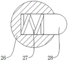
FIG. 4 is a cross-sectional view of a docking post of the present invention;
fig. 5 is a schematic structural diagram of the reset mechanism of the present invention.
In the figure: 1. a support box; 11. a mounting frame; 12. a rotating electric machine; 13. a rotating shaft; 14. a cam; 15. a baffle plate; 2. a support block; 21. a push rod; 22. pushing the plate; 23. a ball bearing; 24. connecting columns; 25. a limiting block; 26. butting columns; 27. a support spring; 28. a fixing pin; 3. mounting a plate; 31. a buffer spring; 32. a buffer column; 33. a roller; 4. positioning a plate; 41. a compression spring; 42. pushing the column; 43. pushing a block; 44. a limit ring.
Detailed Description
In the following description, numerous specific details are set forth in order to provide a more thorough understanding of the present invention. It will be apparent, however, to one skilled in the art, that the present invention may be practiced without one or more of these specific details. In other instances, well-known features have not been described in order to avoid obscuring the utility model.
In order to jack up a mold quickly and facilitate demolding, as shown in fig. 1, fig. 2 and fig. 3, the outer wall of the right side of the support box 1 is fixedly connected with an installation frame 11, a rotating motor 12 is installed in the installation frame 11 through a bolt, an output shaft of the rotating motor 12 is fixedly connected with a rotating shaft 13 through a coupler, one end, far away from the rotating motor 12, of the rotating shaft 13 is rotatably connected with the installation frame 11 through a bearing, the outer wall of the rotating shaft 13 is fixedly connected with a cam 14, the outer wall of the front side of the support box 1 is provided with a rectangular through groove, and a baffle 15 is installed in the rectangular through groove of the support box 1;
a guide mechanism is installed in the support box 1, the guide mechanism comprises a support block 2 and a push plate 22, the right outer wall of the support block 2 is fixedly connected with a push rod 21, the push plate 22 is fixed on the right end face of the push rod 21, the rotating motor 12 drives the cam 14 to rotate, the cam 14 can push the support block 2 to move through the push plate 22 and the push rod 21, the bottom of the support block 2 is symmetrically provided with two rotating grooves, balls 23 are rotationally connected in the rotating grooves at the bottom of the support block 2, the bottom of the support box 1 is provided with a sliding groove for moving the balls 23, the left outer wall of the support block 2 is fixedly connected with a connecting column 24, the right end face of the connecting column 24 is fixedly connected with a positioning part for fixing the position of the support block 2, the positioning part comprises a limit block 25 and a butt joint column 26 fixed on the left end face of the limit block 25, the limit block 25 and the connecting column 24 are welded and fixed, as shown in fig. 4, a mounting hole is formed in the butt joint column 26, a supporting spring 27 is fixedly connected in the mounting hole of the butt joint column 26, and a fixing pin 28 is fixedly connected to one side of the supporting spring 27;
guiding mechanism's top is equipped with ejection mechanism, and ejection mechanism includes mounting panel 3 and buffering post 32, and two spouts have been seted up to mounting panel 3's surface symmetry, and is equipped with buffer spring 31 in mounting panel 3's the spout, and buffering post 32 sets up in buffer spring 31's surface, and buffering post 32's top is equipped with the blotter, and the mount is installed to mounting panel 3's bottom, installs gyro wheel 33 in the mount, and the spacing groove that is used for gyro wheel 33 to remove is seted up on the surface of supporting shoe 2.
In order to enable the ejection mechanism to reset rapidly, as shown in fig. 1, fig. 2 and fig. 5, a reset mechanism for pushing the guide mechanism to reset is arranged on the left side of the guide mechanism, the reset mechanism comprises a positioning plate 4 and a pushing column 42, the positioning plate 4 is fixedly connected with the support box 1 through a bolt, a compression spring 41 is fixedly connected with the outer wall of the right side of the positioning plate 4, a guide hole is formed on the outer wall of the front side of the positioning plate 4, the pushing column 42 is inserted into the guide hole of the positioning plate 4, a connecting hole matched with the butt-joint column 26 is formed in the positioning plate 4, the guide hole is communicated with the connecting hole, when the mold is ejected, the butt-joint column 26 is inserted into the connecting hole of the positioning plate 4, the fixing pin 28 is inserted into the guide hole of the positioning bar, so as to fix the position of the support block 2, a limiting ring 44 is fixedly connected to the outer part of the pushing column 42, so as to prevent the pushing column 42 from falling off, the pushing column 42 extends to the outside of the support box 1, and the end surface of the pushing column 42 positioned outside the supporting box 1 is fixedly connected with a pushing block 43.
Working principle, this plastics injection mold's ejection mechanism, when using, start rotating electrical machines 12, rotating electrical machines 12 drives rotation axis 13 and cam 14 and rotates, cam 14 promotes supporting shoe 2 and removes in supporting box 1, gyro wheel 33 removes on the surface of supporting shoe 2, thereby upwards jack-up mounting panel 3 and buffer post 32, thereby jack-up the mould, when jacking up the mould, peg graft in the connecting hole of locating plate 4 to post 26, fixing pin 28 pegs graft in the guiding hole of locating plate 4, thereby fix the position of supporting shoe 2, take out the back with the mould, through promoting post 42 inside extrusion fixing pin 28, make fixing pin 28 retract to in the post 26, under compression spring 41's elastic force effect, promote supporting shoe 2 and reset.
Finally, it should be noted that: the foregoing is merely a preferred embodiment of the present invention and is not intended to limit the present invention.
Claims (7)
1. The utility model provides a plastics injection mold's ejection mechanism, includes supporting box (1), sets up the guiding mechanism in supporting box (1) and sets up the ejection mechanism in the guiding mechanism top, its characterized in that: the left side of guiding mechanism is equipped with the canceling release mechanical system that promotes the guiding mechanism and reset, canceling release mechanical system includes locating plate (4) and promotion post (42), the right side outer wall fixedly connected with compression spring (41) of locating plate (4), the guiding hole has been seted up to the front side outer wall of locating plate (4), and promotes post (42) and peg graft in the guiding hole of locating plate (4), guiding mechanism includes supporting shoe (2) and push pedal (22), the right side outer wall fixedly connected with catch bar (21) of supporting shoe (2), the right-hand member face of catch bar (21) is fixed in push pedal (22), the left side outer wall fixedly connected with spliced pole (24) of supporting shoe (2), the right-hand member face fixedly connected with of spliced pole (24) is used for carrying out the location portion of fixing to supporting shoe (2) position.
2. The ejection mechanism of a plastic injection mold according to claim 1, wherein: the locating part comprises a limiting block (25) and a butting column (26) fixed on the left end face of the limiting block (25), a mounting hole is formed in the butting column (26), a supporting spring (27) is fixedly connected in the mounting hole of the butting column (26), a fixing pin (28) is fixedly connected to one side of the supporting spring (27), and a connecting hole matched with the butting column (26) is formed in the locating plate (4).
3. The ejection mechanism of a plastic injection mold according to claim 1, wherein: the ejection mechanism comprises a mounting plate (3) and a buffer column (32), two sliding grooves are symmetrically formed in the surface of the mounting plate (3), a buffer spring (31) is arranged in each sliding groove of the mounting plate (3), the buffer column (32) is arranged on the surface of the buffer spring (31), a fixing frame is installed at the bottom of the mounting plate (3), and a roller (33) is installed in the fixing frame.
4. The ejection mechanism of a plastic injection mold as claimed in claim 1, wherein: the right side outer wall fixedly connected with mounting bracket (11) of supporting box (1), install rotating electrical machines (12) in mounting bracket (11), the output shaft of rotating electrical machines (12) passes through shaft coupling fixedly connected with rotation axis (13), the outer wall fixedly connected with cam (14) of rotation axis (13).
5. The ejection mechanism of a plastic injection mold according to claim 1, wherein: the outside fixedly connected with spacing ring (44) of promotion post (42), promote outside post (42) extends to supporting box (1), and promote the terminal surface fixedly connected with ejector pad (43) that post (42) are located supporting box (1) outside.
6. The ejection mechanism of a plastic injection mold according to claim 1, wherein: two rotating grooves are symmetrically formed in the bottom of the supporting block (2), balls (23) are rotatably connected to the rotating grooves in the bottom of the supporting block (2), and sliding grooves used for the balls (23) to move are formed in the bottom of the supporting box (1).
7. The ejection mechanism of a plastic injection mold according to claim 4, wherein: a rectangular through groove is formed in the outer wall of the front side of the supporting box (1), and a baffle (15) is installed in the rectangular through groove of the supporting box (1).
Priority Applications (1)
| Application Number | Priority Date | Filing Date | Title |
|---|---|---|---|
| CN202220073109.8U CN216732846U (en) | 2022-01-12 | 2022-01-12 | Ejection mechanism of plastic injection mold |
Applications Claiming Priority (1)
| Application Number | Priority Date | Filing Date | Title |
|---|---|---|---|
| CN202220073109.8U CN216732846U (en) | 2022-01-12 | 2022-01-12 | Ejection mechanism of plastic injection mold |
Publications (1)
| Publication Number | Publication Date |
|---|---|
| CN216732846U true CN216732846U (en) | 2022-06-14 |
Family
ID=81911884
Family Applications (1)
| Application Number | Title | Priority Date | Filing Date |
|---|---|---|---|
| CN202220073109.8U Active CN216732846U (en) | 2022-01-12 | 2022-01-12 | Ejection mechanism of plastic injection mold |
Country Status (1)
| Country | Link |
|---|---|
| CN (1) | CN216732846U (en) |
-
2022
- 2022-01-12 CN CN202220073109.8U patent/CN216732846U/en active Active
Similar Documents
| Publication | Publication Date | Title |
|---|---|---|
| CN201371559Y (en) | Seesaw ejecting demolding mechanism and injection mold | |
| CN210139593U (en) | Injection mold ejection mechanism capable of achieving rapid demolding | |
| CN216732846U (en) | Ejection mechanism of plastic injection mold | |
| CN210061789U (en) | Injection mold convenient to dismouting water pump impeller | |
| CN101306570A (en) | Mold device and injection molding method | |
| CN209699790U (en) | A kind of injection mold cavity ejection effort-saving mechanism | |
| CN203765953U (en) | Accurate injection molding mold of synchronous wheel plastic element | |
| CN113043541A (en) | Anti-sticking inclined ejection structure of injection mold | |
| CN213006348U (en) | Ejection structure of injection mold | |
| CN211843034U (en) | Forming die of high performance engineering machine tool foundry goods | |
| CN210733077U (en) | Injection mold for machining of X-ray imaging equipment parts | |
| CN107972233B (en) | Injection mold for bracket of small-sized automobile air conditioner | |
| CN211363280U (en) | Mold ejection device | |
| CN213766954U (en) | Steel injection mold with ejection structure | |
| CN216300005U (en) | Mold for inclined top demolding | |
| CN211640774U (en) | Injection molding pipe fitting insert forming die | |
| CN220280392U (en) | Injection molding demoulding device | |
| CN220349030U (en) | Blow molding equipment for automobile bumper | |
| CN212948989U (en) | Driving mechanism for injection mold | |
| CN219360191U (en) | Mould demoulding device | |
| CN217319138U (en) | Molding and demolding mechanism | |
| CN221067045U (en) | Washing machine roller injection mold convenient for demolding | |
| CN218803814U (en) | Multi-injection mold machining device | |
| CN217495081U (en) | Multi-cavity movable mould blank pouring device of PP material bottle blank forming machine | |
| CN215849461U (en) | Demoulding mechanism for bottle cap injection mould |
Legal Events
| Date | Code | Title | Description |
|---|---|---|---|
| GR01 | Patent grant | ||
| GR01 | Patent grant |