CN216693614U - Dust recovery unit that falls of rotation air preheater - Google Patents
Dust recovery unit that falls of rotation air preheater Download PDFInfo
- Publication number
- CN216693614U CN216693614U CN202220261055.8U CN202220261055U CN216693614U CN 216693614 U CN216693614 U CN 216693614U CN 202220261055 U CN202220261055 U CN 202220261055U CN 216693614 U CN216693614 U CN 216693614U
- Authority
- CN
- China
- Prior art keywords
- heat exchange
- dust
- flue gas
- gear
- air preheater
- Prior art date
- Legal status (The legal status is an assumption and is not a legal conclusion. Google has not performed a legal analysis and makes no representation as to the accuracy of the status listed.)
- Active
Links
Images


Classifications
-
- Y—GENERAL TAGGING OF NEW TECHNOLOGICAL DEVELOPMENTS; GENERAL TAGGING OF CROSS-SECTIONAL TECHNOLOGIES SPANNING OVER SEVERAL SECTIONS OF THE IPC; TECHNICAL SUBJECTS COVERED BY FORMER USPC CROSS-REFERENCE ART COLLECTIONS [XRACs] AND DIGESTS
- Y02—TECHNOLOGIES OR APPLICATIONS FOR MITIGATION OR ADAPTATION AGAINST CLIMATE CHANGE
- Y02E—REDUCTION OF GREENHOUSE GAS [GHG] EMISSIONS, RELATED TO ENERGY GENERATION, TRANSMISSION OR DISTRIBUTION
- Y02E20/00—Combustion technologies with mitigation potential
- Y02E20/34—Indirect CO2mitigation, i.e. by acting on non CO2directly related matters of the process, e.g. pre-heating or heat recovery
Landscapes
- Air Supply (AREA)
Abstract
The utility model discloses a falling ash recovery device of a rotary air preheater, which comprises a heat exchange bin, wherein a heat exchange rotor is rotationally arranged in the heat exchange bin, partition plates are arranged on the upper side and the lower side of the heat exchange rotor, the partition plates divide the interior of the heat exchange bin into a smoke area and an air area, a smoke outlet is arranged on the lower side of the smoke area, a filter funnel is fixedly arranged in the smoke outlet, and a conveying pipe transversely penetrating through the smoke outlet is fixedly arranged at a leakage opening at the lower end of the filter funnel. The utility model can filter dust and impurities contained in the smoke flowing to the smoke outlet by arranging the filter funnel and the conveying pipe, and the dust and impurities are retained on the filter funnel, while the smoke gas is smoothly discharged from the smoke outlet, then the dust retained on the filter funnel enters the conveying pipe through the leakage opening of the filter funnel under the drive of gravity and airflow, and then the dust can be separately and intensively discharged by the spiral blade driven by the motor in the conveying pipe, thereby facilitating the collection and treatment of the dust.
Description
Technical Field
The utility model relates to the technical field of air preheaters, in particular to a falling ash recovery device of a rotary air preheater.
Background
The air preheater is a device widely used in utility boilers for improving heat exchange performance of the boiler and reducing energy consumption, and can be classified into a tubular type and a rotary type, wherein the rotary type air preheater transfers heat in a regenerative manner, and the heat transfer is achieved by alternately flowing flue gas and air through heating surfaces of an inner rotor of the preheater.
The patent document CN113108304A proposes a flue gas outlet device of an air preheater, which comprises a flue, wherein the flue comprises a flue gas input end, a flue gas output end and a flue gas dust collecting end, which are connected with a main body of the air preheater; the connection part is communicated with the smoke input end, the smoke output end and the dust collecting end; the linking part is provided with a slope surface for colliding flue gas to subside dust, the flue gas dust collecting end is used for collecting the settled dust, the flue gas output end is used for outputting the flue gas after the dust is settled, the flue gas dust collecting end is arranged below the linking part, and the flue gas dust collecting end comprises a sedimentation ash bucket connected with the linking part and a closed ash discharging device connected with the sedimentation ash bucket. The utility model effectively solves the problems of increased flue resistance, increased power consumption of the induced draft fan, increased exhaust gas temperature, reduced heat exchange effect of the air preheater and increased heat loss caused by flue dust deposition, recycles dust, protects environment and increases income.
When the waste heat in the flue gas is recovered by using the air preheater, dust and impurities contained in the flue gas can be retained in the air preheater, so that the heat exchange efficiency of the air preheater is affected, the flue gas is easy to directly pass through the air preheater and then is discharged to a subsequent pipeline or the outside, and then pipeline erosion or air pollution and other problems are caused.
SUMMERY OF THE UTILITY MODEL
The utility model aims to provide a falling ash recovery device of a rotary air preheater so as to solve the problems in the background technology.
In order to achieve the purpose, the utility model provides the following technical scheme: the utility model provides a rotation air preheater's ash recovery unit that falls, includes the heat transfer storehouse, the heat transfer storehouse internal rotation is provided with the heat transfer rotor, the downside all is provided with the baffle on the heat transfer rotor, the baffle divides the heat transfer storehouse inside into flue gas district and air district, flue gas district downside is provided with the outlet flue, the internal fixed filter funnel that is provided with of outlet flue, filter funnel lower extreme leak department is fixed and is provided with the conveyer pipe that transversely runs through the outlet flue, the conveyer pipe internal rotation is provided with helical blade, the rotation of heat transfer rotor and helical blade's rotation all are through the motor drive of the outer fixed mounting in heat transfer storehouse.
Preferably, the motor is provided with an upper output end and a lower output end, a gear ring is fixedly arranged on the outer side of the heat exchange rotor, and a first gear matched with the gear ring is coaxially and fixedly connected with one output end of the motor.
Preferably, the other output end of the motor is coaxially and fixedly connected with a first bevel gear, the first bevel gear is meshed with a second bevel gear, the second bevel gear is coaxially and fixedly connected with a transmission shaft, and the transmission shaft rotatably penetrates through the conveying pipe and is coaxially and fixedly connected with the helical blades.
Preferably, the conveying pipe penetrates through one end extending out of the smoke outlet and is provided with an ash discharge port.
Preferably, a cleaning brush attached to the top of the heat exchange rotor is fixedly arranged in the smoke area.
Preferably, the flue gas area is internally and rotatably provided with two sweeping plates capable of sweeping the inner bottom surface of the flue gas area, and the heat exchange bin is internally provided with a driving assembly for driving the two sweeping plates to synchronously rotate in opposite directions.
Preferably, the driving assembly comprises a driving rod arranged in the heat exchange bin in a rotating mode, a second gear is fixedly connected to the driving rod coaxially, a third gear is connected to the driving rod in a meshing mode, a driven rod arranged in the heat exchange bin is rotatably connected to the third gear coaxially, and the sweeping plates are fixedly connected with the driving rod and the driven rod respectively.
Preferably, a slope body is arranged at the edge of the inner bottom surface of the heat exchange bin, and the appearance of the free end part of the sweeping plate is matched with the slope body.
Compared with the prior art, the utility model has the beneficial effects that:
this rotation air preheater's ash recovery unit that falls filters funnel and conveyer pipe through setting up, can filter the dust impurity that contains in the flue gas that flows toward the outlet flue, and remain on filtering the funnel, and flue gas is discharged by the outlet flue smoothly, then, the dust that is detained on filtering the funnel is under the drive of gravity and air current, in a dispute via filtering the funnel leak entering conveyer pipe, then, it can concentrate the discharge alone with the dust through the rotatory helical blade of motor drive in the conveyer pipe, made things convenient for the collection processing to the dust, prevent the dust along with the air pollution that the flue gas direct emission caused.
Drawings
FIG. 1 is a schematic overall sectional view of the present invention;
FIG. 2 is a schematic front sectional view of the present invention;
FIG. 3 is a schematic side sectional view of the present invention;
FIG. 4 is a schematic top cross-sectional view of the present invention;
fig. 5 is an enlarged schematic view of the structure at a in fig. 3 according to the present invention.
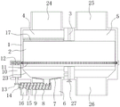
In the figure: 1. a heat exchange bin; 2. a heat exchange rotor; 3. a partition plate; 4. a flue gas zone; 5. an air zone; 6. a smoke outlet; 7. filtering the mixture by a funnel; 8. a delivery pipe; 9. a helical blade; 10. a motor; 11. a toothed ring; 12. a first gear; 13. a first bevel gear; 14. a second bevel gear; 15. a drive shaft; 16. an ash discharge port; 17. a cleaning brush; 18. sweeping the board; 19. a drive rod; 20. a second gear; 21. a third gear; 22. a driven lever; 23. a slope body; 24. a smoke inlet; 25. an air outlet; 26. an air inlet; 27. a handle.
Detailed Description
Referring to fig. 1-5, the falling ash recovery device of the rotary air preheater provided in the embodiment of the present invention includes a heat exchange chamber 1, a heat exchange rotor 2 is rotatably disposed in the heat exchange chamber 1, partition plates 3 are disposed on upper and lower sides of the heat exchange rotor 2, the partition plates 3 divide the interior of the heat exchange chamber 1 into a smoke region 4 and an air region 5, a smoke outlet 6 is disposed on a lower side of the smoke region 4, a filter funnel 7 is fixedly disposed in the smoke outlet 6, a delivery pipe 8 transversely penetrating the smoke outlet 6 is fixedly disposed at a lower end leakage opening of the filter funnel 7, a helical blade 9 is rotatably disposed in the delivery pipe 8, and rotation of the heat exchange rotor 2 and rotation of the helical blade 9 are both driven by a motor 10 fixedly disposed outside the heat exchange chamber 1.
Specifically, the heat exchange bin 1 is used for providing a relatively closed occasion for heat exchange between flue gas and air; the heat exchange rotor 2 is formed by connecting and combining radiating fins easy to conduct heat, a hollow structure is further arranged on the heat exchange rotor 2, gas can conveniently circulate, the heat exchange rotor 2 can quickly absorb waste heat carried by smoke in the smoke area 4 and store the waste heat, and meanwhile, the stored heat can be conducted to cold air in the air area 5 to preheat the cold air; the partition plate 3 is used for preventing the smoke from directly contacting with the air, so that the generation of turbulent flow is avoided; a smoke inlet 24 is arranged at the upper side of the smoke area 4, smoke enters the heat exchange bin 1 through the smoke inlet 24, then contacts with the heat exchange rotor 2 to lose heat, and finally is discharged outwards through a smoke outlet 6; the upper side of the air zone 5 is provided with an air outlet 25, the lower side is provided with an air inlet 26, cold air enters the heat exchange bin 1 through the air inlet 26, then contacts with the heat exchange rotor 2 and absorbs heat, and finally is discharged from the air outlet 25; the top of the filter funnel 7 is provided with a conical filter screen structure, the leakage opening is provided with a tubular structure, and the filter screen structure of the filter funnel 7 can block dust and impurities in the flue gas, so that the flue gas can smoothly pass through; the conveying pipe 8 is communicated with a leakage opening of the filtering funnel 7; the outer circle diameter of helical blade 9 equals with conveyer pipe 8's internal diameter for, helical blade 9 can restrict gaseous circulation, makes in the difficult entering conveyer pipe 8 of flue gas, then helical blade 9 can drive the dust removal in the conveyer pipe 8 through the spiral feed effect that takes place when rotating. In practical use, the flue gas flows to the flue gas outlet 6 after heat consumption in the heat exchange bin 1, then is subjected to the filtering action of the filtering funnel 7, so that dust and impurities in the flue gas are separated from the flue gas, the dust is retained at the upper end of the filtering funnel 7, and the flue gas smoothly passes through the filtering funnel 7 and then is discharged outwards through the flue gas outlet 6; the dust retained on the filter funnel 7 enters the conveying pipe 8 through the leakage opening of the filter funnel 7 under the driving of gravity and air flow, and then the motor 10 drives the helical blade 9 to rotate to generate a helical feeding effect, so that the dust in the conveying pipe 8 leaves the smoke outlet 6 and is discharged independently and intensively, the dust is convenient to collect and treat, and the dust is prevented from being directly discharged along with smoke to cause air pollution.
Compared with the prior art, the dust recovery device of the rotary air preheater provided by the embodiment of the utility model is provided with the filter funnel 7 and the conveying pipe 8, so that dust impurities contained in smoke flowing to the smoke outlet 6 can be filtered and retained on the filter funnel 7, smoke gas is smoothly discharged from the smoke outlet 6, then, dust retained on the filter funnel 7 enters the conveying pipe 8 through the leakage opening of the filter funnel 7 under the driving of gravity and airflow, and then, the dust can be separately and intensively discharged through the spiral blade 9 driven by the motor 10 to rotate in the conveying pipe 8, so that the dust is conveniently collected and treated, and air pollution caused by direct discharge of the dust along with the smoke is prevented.
As a preferred technical solution of this embodiment, the motor 10 has an upper output end and a lower output end, the outer side of the heat exchange rotor 2 is fixedly provided with the gear ring 11, one output end of the motor 10 is coaxially and fixedly connected with a first gear 12 matched with the gear ring 11, specifically, when the motor 10 is started, the first gear 12 is driven to rotate, and the first gear 12 drives the heat exchange rotor 2 to rotate through the meshing action with the gear ring 11, so that the heating surface of the heat exchange rotor 2 is switched between the flue gas area 4 and the air area 5 to realize the heat exchange function.
As a preferred technical solution of this embodiment, a first bevel gear 13 is fixedly connected to another output end of the motor 10 coaxially, the first bevel gear 13 is engaged with a second bevel gear 14, the second bevel gear 14 is fixedly connected to a transmission shaft 15 coaxially, the transmission shaft 15 rotates to penetrate through the conveying pipe 8 and is fixedly connected to the spiral blade 9 coaxially, specifically, when the motor 10 is started, the first bevel gear 13 is driven to rotate, the first bevel gear 13 drives the transmission shaft 15 to rotate through engagement with the second bevel gear 14, the transmission shaft 15 drives the spiral blade 9 to rotate, so that the spiral blade 9 can generate a spiral feeding effect on dust in the conveying pipe 8, and the dust moves in the conveying pipe 8, leaves the smoke outlet 6 and is discharged outwards separately.
As a further preferable technical solution of the present embodiment, the conveying pipe 8 is provided with an ash discharge port 16 penetrating through one end extending out of the smoke outlet 6, and specifically, the ash discharge port 16 is provided for concentrated discharge of dust and is independent from the outer side of the smoke outlet 6.
In another embodiment of the present invention, a cleaning brush 17 attached to the top of the heat exchange rotor 2 is fixedly disposed in the flue gas area 4, specifically, when flue gas enters the heat exchange chamber 1 from the flue gas inlet 24 and contacts the heat exchange rotor 2, dust is retained on the upper end surface of the heat exchange rotor 2, and the cleaning brush 17 is disposed such that when the heat exchange rotor 2 rotates, the upper end surface of the flue gas can be continuously scraped by the cleaning brush 17, so that the retained dust is cleaned, and the influence of the dust on the heat exchange performance of the heat exchange rotor 2 due to the dust covering the surface of the heat exchange rotor 2 is reduced.
In another embodiment of the present invention, two sweeping plates 18 capable of sweeping the inner bottom surface of the flue gas zone 4 are rotatably disposed in the flue gas zone 4, a driving component for driving the two sweeping plates 18 to rotate synchronously in opposite directions is disposed in the heat exchange chamber 1, specifically, the flue gas outlet 6 usually does not cover the inner bottom surface of the whole flue gas zone 4, so that stubborn dust and impurities may be retained on the inner bottom surface of the flue gas zone 4, the sweeping plates 18 are disposed in a manner that they sweep the inner bottom surface of the flue gas zone 4 by rotating, and the sweeping direction is a direction close to the flue gas outlet 6, so that stubborn dust retained in the flue gas zone 4 can be brought to the flue gas outlet 6, and thus, the dust can be conveniently discharged and recycled.
As a preferred technical solution of this embodiment, the driving assembly includes a driving rod 19 rotatably disposed in the heat exchange chamber 1, a second gear 20 is coaxially and fixedly connected to the driving rod 19, a third gear 21 is engaged and connected to the second gear 20, a driven rod 22 rotatably disposed in the heat exchange chamber 1 is coaxially and fixedly connected to the third gear 21, the two sweeping plates 18 are respectively and fixedly connected to the driving rod 19 and the driven rod 22, specifically, one end of the driving rod 19 extends to the outer side of the heat exchange chamber 1 and is provided with a handle 27, the second gear 20 is engaged with the third gear 21, so that the rotation directions of the driving rod 19 and the driven rod 22 are opposite, and then the two sweeping plates 18 are driven to rotate synchronously in opposite directions, thereby causing the sweep plate 18 to rotate in a direction synchronously toward the smoke outlet 6 or in a direction synchronously away from the smoke outlet 6 in the smoke zone 4, and two sweep boards 18 and can form the package and press from both sides the effect, guarantee that the stubborn dust that the bottom surface is detained in flue gas zone 4 can both be swept to outlet 6 department by sweeping board 18. In practical use, the driving rod 19 is rotated by the handle 27, the driving rod 19 drives the second gear 20 to rotate, the second gear 20 drives the driven rod 22 to rotate in the direction opposite to that of the driving rod 19 through the meshing relationship with the third gear 21, then the driving rod 19 and the driven rod 22 synchronously drive the two sweeping plates 18 to rotate in the opposite direction in the smoke area 4, and when the two sweeping plates 18 synchronously rotate in the direction close to the smoke outlet 6, stubborn dust remained on the ground in the smoke area 4 can be cleaned to the smoke outlet 6.
As a further preferred technical scheme of this embodiment, a slope 23 is disposed at the bottom edge in the heat exchange bin 1, and the shape of the free end of the sweeping plate 18 matches with the slope 23, specifically, the slope 23 is disposed, so that most of the dust can be guided by the slope to be close to the smoke outlet 6, and then can be moved to the smoke outlet 6 by sweeping the sweeping plate 18.
The working principle is as follows: when the dust and impurities in the flue gas need to be intensively recovered, the flue gas firstly flows to the flue gas outlet 6 after heat consumption is completed in the heat exchange bin 1, and then is subjected to the filtering action of the filtering funnel 7, so that the dust and impurities in the flue gas are separated from the flue gas, the dust is kept at the upper end of the filtering funnel 7, and the flue gas is smoothly discharged through the flue gas outlet 6 after passing through the filtering funnel 7; the dust that remains on filter funnel 7 is under the drive of gravity and air current, in many times get into conveyer pipe 8 via filter funnel 7 leak, then, the output of motor 10 drives first bevel gear 13 and rotates, first bevel gear 13 drives transmission shaft 15 through the meshing relation with second bevel gear 14 and rotates, transmission shaft 15 drives helical blade 9 again and rotates, thereby make helical blade 9 can produce the spiral feeding effect to the dust in conveyer pipe 8, make the dust remove in conveyer pipe 8 and leave outlet 6, and at last by the outside concentrated discharge of row's ash mouth 16, made things convenient for the independent collection of dust to handle, prevent the air pollution that the dust directly discharged and cause along with the flue gas.
In addition, after this air preheater used at an end time, can detain some stubborn dust in the flue gas district 4, then accessible handle 27 rotates actuating lever 19, actuating lever 19 drives second gear 20 and rotates, second gear 20 then drives driven lever 22 and actuating lever 19 opposite direction through the meshing relation with third gear 21 and rotates, then, actuating lever 19 and driven lever 22 drive two synchronous to sweep board 18 and rotate to opposite direction in flue gas district 4, when two sweep board 18 rotate to the direction that is close to outlet 6 in step, can clean the stubborn dust that the ground was detained in flue gas district 4 to outlet 6, then pass through the separation and the transportation process of above-mentioned flue gas dust and collect the processing alone with the dust.
Claims (8)
1. The utility model provides a rotation air preheater's ash recovery unit that falls, includes heat transfer storehouse (1), its characterized in that: the internal rotation of heat transfer storehouse (1) is provided with heat transfer rotor (2), downside all is provided with baffle (3) on heat transfer rotor (2), baffle (3) divide heat transfer storehouse (1) inside into flue gas district (4) and air district (5), flue gas district (4) downside is provided with outlet flue (6), outlet flue (6) internal fixation is provided with filter funnel (7), filter funnel (7) lower extreme leak department is fixed and is provided with conveyer pipe (8) that transversely runs through outlet flue (6), conveyer pipe (8) internal rotation is provided with helical blade (9), the rotation of heat transfer rotor (2) and the rotation of helical blade (9) are all through motor (10) the drive of heat transfer storehouse (1) outer fixed mounting.
2. The ash falling recovery device of the rotary air preheater as recited in claim 1, wherein: the motor (10) is provided with an upper output end and a lower output end, a gear ring (11) is fixedly arranged on the outer side of the heat exchange rotor (2), and a first gear (12) matched with the gear ring (11) is coaxially and fixedly connected with one output end of the motor (10).
3. The fallen ash recovery device of the rotary air preheater as claimed in claim 2, wherein: the motor is characterized in that a first bevel gear (13) is coaxially and fixedly connected with the other output end of the motor (10), a second bevel gear (14) is meshed and connected with the first bevel gear (13), a transmission shaft (15) is coaxially and fixedly connected with the second bevel gear (14), and the transmission shaft (15) rotates to penetrate through the conveying pipe (8) and is coaxially and fixedly connected with the helical blade (9).
4. The fallen ash recovery device of the rotary air preheater as claimed in claim 1, wherein: the conveying pipe (8) penetrates through one end extending out of the smoke outlet (6) and is provided with an ash discharging opening (16).
5. The fallen ash recovery device of the rotary air preheater as claimed in claim 1, wherein: and a cleaning brush (17) attached to the top of the heat exchange rotor (2) is fixedly arranged in the smoke area (4).
6. The fallen ash recovery device of the rotary air preheater as claimed in claim 1, wherein: two sweeping plates (18) capable of sweeping the inner bottom surface of the flue gas area (4) are rotatably arranged in the flue gas area (4), and a driving assembly for driving the two sweeping plates (18) to synchronously rotate in opposite directions is arranged in the heat exchange bin (1).
7. The fallen ash recovery device of the rotary air preheater as claimed in claim 6, wherein: drive assembly includes actuating lever (19) that the internal rotation of heat transfer storehouse (1) set up, coaxial fixedly connected with second gear (20) on actuating lever (19), second gear (20) meshing is connected with third gear (21), the coaxial fixedly connected with of third gear (21) rotates driven lever (22) that set up in heat transfer storehouse (1), two sweep board (18) respectively with actuating lever (19), driven lever (22) fixed connection.
8. The fallen ash recovery device of the rotary air preheater as claimed in claim 7, wherein: a slope body (23) is arranged at the edge of the inner bottom surface of the heat exchange bin (1), and the appearance of the free end part of the sweeping plate (18) is matched with the slope body (23).
Priority Applications (1)
| Application Number | Priority Date | Filing Date | Title |
|---|---|---|---|
| CN202220261055.8U CN216693614U (en) | 2022-02-09 | 2022-02-09 | Dust recovery unit that falls of rotation air preheater |
Applications Claiming Priority (1)
| Application Number | Priority Date | Filing Date | Title |
|---|---|---|---|
| CN202220261055.8U CN216693614U (en) | 2022-02-09 | 2022-02-09 | Dust recovery unit that falls of rotation air preheater |
Publications (1)
| Publication Number | Publication Date |
|---|---|
| CN216693614U true CN216693614U (en) | 2022-06-07 |
Family
ID=81824197
Family Applications (1)
| Application Number | Title | Priority Date | Filing Date |
|---|---|---|---|
| CN202220261055.8U Active CN216693614U (en) | 2022-02-09 | 2022-02-09 | Dust recovery unit that falls of rotation air preheater |
Country Status (1)
| Country | Link |
|---|---|
| CN (1) | CN216693614U (en) |
-
2022
- 2022-02-09 CN CN202220261055.8U patent/CN216693614U/en active Active
Similar Documents
| Publication | Publication Date | Title |
|---|---|---|
| CN209139464U (en) | A kind of construction waste processing system | |
| CN216693614U (en) | Dust recovery unit that falls of rotation air preheater | |
| CN116768239B (en) | Large-particle salt upgrading equipment capable of removing sundries in raw salt | |
| CN214502021U (en) | Wild pepper processing drying-machine | |
| CN108079731A (en) | A kind of continuous dust-extraction unit of energy saving smoke | |
| CN113291750A (en) | Fly ash, slag's guide cleaning device | |
| CN217015966U (en) | Pneumatic mixing cyclone tower suitable for flue gas treatment | |
| CN112108441A (en) | Multi-functional medicinal material processingequipment | |
| CN208832479U (en) | The anti-hot gas that a kind of Biohazard Waste Disposal destroy rotary kiln overflows in bulk set | |
| CN217235643U (en) | Purifier for coal-fired burner | |
| CN114738782A (en) | Environment-friendly thermal power waste heat utilization equipment | |
| CN212721012U (en) | Low-temperature waste gas waste heat recovery processing device | |
| CN218011662U (en) | Power plant waste heat recovery device | |
| CN112122101A (en) | Ash treatment device after environmental garbage power generation | |
| CN213686855U (en) | Special explosion-proof catalytic combustion device of chemical industry | |
| CN215539516U (en) | Boiler tail gas cooling device | |
| CN215480483U (en) | Utilize flue gas waste heat processing mud low temperature mummification device | |
| CN215585808U (en) | Dry-method purifying and dedusting device for blast furnace | |
| CN213146608U (en) | Boiler waste gas heat collection device | |
| CN220153282U (en) | Exhaust passage of refractory kiln | |
| CN209910313U (en) | Grain drying machine | |
| CN220951202U (en) | Waste liquid purifying treatment equipment with energy saving and emission reduction functions | |
| CN220849814U (en) | Diesel generator exhaust treatment device | |
| CN211963487U (en) | Hopper of pulse dust collector | |
| CN218306779U (en) | Environment-friendly bag-type dust collector |
Legal Events
| Date | Code | Title | Description |
|---|---|---|---|
| GR01 | Patent grant | ||
| GR01 | Patent grant |