CN216660055U - Instrument board beam assembly and vehicle - Google Patents
Instrument board beam assembly and vehicle Download PDFInfo
- Publication number
- CN216660055U CN216660055U CN202220161383.0U CN202220161383U CN216660055U CN 216660055 U CN216660055 U CN 216660055U CN 202220161383 U CN202220161383 U CN 202220161383U CN 216660055 U CN216660055 U CN 216660055U
- Authority
- CN
- China
- Prior art keywords
- beam body
- vehicle
- bracket
- instrument panel
- steering column
- Prior art date
- Legal status (The legal status is an assumption and is not a legal conclusion. Google has not performed a legal analysis and makes no representation as to the accuracy of the status listed.)
- Active
Links
- 229920000049 Carbon (fiber) Polymers 0.000 claims description 19
- 239000004917 carbon fiber Substances 0.000 claims description 19
- VNWKTOKETHGBQD-UHFFFAOYSA-N methane Chemical compound C VNWKTOKETHGBQD-UHFFFAOYSA-N 0.000 claims description 16
- 239000000463 material Substances 0.000 claims description 11
- 238000000034 method Methods 0.000 claims description 10
- 230000008569 process Effects 0.000 claims description 6
- 239000007769 metal material Substances 0.000 claims description 3
- 238000009434 installation Methods 0.000 claims 2
- 238000010276 construction Methods 0.000 abstract description 3
- 229910000861 Mg alloy Inorganic materials 0.000 description 6
- 238000004026 adhesive bonding Methods 0.000 description 6
- 239000000956 alloy Substances 0.000 description 4
- 229910000838 Al alloy Inorganic materials 0.000 description 3
- 239000010959 steel Substances 0.000 description 3
- 239000013585 weight reducing agent Substances 0.000 description 3
- 229910000831 Steel Inorganic materials 0.000 description 2
- 239000000853 adhesive Substances 0.000 description 2
- 230000001070 adhesive effect Effects 0.000 description 2
- 239000002131 composite material Substances 0.000 description 2
- 230000007547 defect Effects 0.000 description 2
- 238000004512 die casting Methods 0.000 description 2
- 210000003195 fascia Anatomy 0.000 description 2
- 239000004033 plastic Substances 0.000 description 2
- 239000000243 solution Substances 0.000 description 2
- 229910000851 Alloy steel Inorganic materials 0.000 description 1
- OKTJSMMVPCPJKN-UHFFFAOYSA-N Carbon Chemical compound [C] OKTJSMMVPCPJKN-UHFFFAOYSA-N 0.000 description 1
- 230000009286 beneficial effect Effects 0.000 description 1
- 229910052799 carbon Inorganic materials 0.000 description 1
- 238000000748 compression moulding Methods 0.000 description 1
- 230000003247 decreasing effect Effects 0.000 description 1
- 238000005516 engineering process Methods 0.000 description 1
- 238000001746 injection moulding Methods 0.000 description 1
- 230000003993 interaction Effects 0.000 description 1
- 238000012986 modification Methods 0.000 description 1
- 230000004048 modification Effects 0.000 description 1
- 239000004417 polycarbonate Substances 0.000 description 1
- 229920000515 polycarbonate Polymers 0.000 description 1
- 239000000758 substrate Substances 0.000 description 1
- 238000004260 weight control Methods 0.000 description 1
Images


Landscapes
- Body Structure For Vehicles (AREA)
Abstract
The application relates to an instrument board beam assembly and a vehicle. The instrument board beam assembly comprises a beam body, a steering column mounting support and at least one side support, wherein the steering column mounting support is mounted on the beam body; the vehicle body supporting structure comprises a beam body, and is characterized by further comprising a central support arranged on the beam body, wherein the central support is used for supporting the beam body in a first direction and a second direction, the first direction is the front-back direction of a vehicle, and the second direction is the height direction of the vehicle. The application provides a scheme can alleviate instrument board beam assembly's weight through optimizing instrument board beam assembly structural design to satisfy body construction's lightweight requirement.
Description
Technical Field
The application relates to the technical field of vehicles, especially, relate to instrument board beam assembly and vehicle.
Background
A Cross Beam (Cross Car Beam) of an automobile instrument panel is an important automobile body part for installing and fixing the instrument panel, improving the rigidity of an automobile body and protecting the safety of passengers in a cockpit.
In the related art, the automobile instrument panel beam is usually made of steel, aluminum alloy or magnesium alloy and other alloy materials, and is influenced by factors such as materials, processes, structural design and the like, so that the automobile instrument panel beam is difficult to further realize light weight, and cannot meet the light weight requirement of an automobile body structure.
SUMMERY OF THE UTILITY MODEL
In order to solve or partially solve the problems existing in the related art, the application provides an instrument panel beam assembly and a vehicle.
The first aspect of the application provides an instrument panel beam assembly, which comprises a beam body, a steering column mounting support and at least one side support, wherein the steering column mounting support is mounted on the beam body;
the vehicle body supporting structure comprises a beam body, and is characterized by further comprising a central support arranged on the beam body, wherein the central support is used for supporting the beam body in a first direction and a second direction, the first direction is the front-back direction of a vehicle, and the second direction is the height direction of the vehicle.
In one embodiment, at least one of the steering column mounting bracket, the side bracket and the central bracket is glued to the beam body; or
At least one of the steering column mounting bracket, the side bracket and the central bracket is riveted to the beam body; or
At least one of the steering column mounting bracket, the side bracket and the center bracket is connected to the beam body by a fastener.
In one embodiment, the beam body is a tubular structure;
the thickness of the pipe wall of the beam body corresponding to a main driving position of the vehicle is larger than that of the pipe wall corresponding to a secondary driving position of the vehicle.
In one embodiment, the beam body is made of carbon fiber material through a layering process, wherein the thickness of the layer of the carbon fiber material of the beam body corresponding to the main driving position of the vehicle is larger than that of the layer corresponding to the auxiliary driving position of the vehicle.
In one embodiment, the central support includes a first end connected to the beam and a second end connected to the vehicle body, and the first end is provided with a support surface for supporting the beam in the first direction and the second direction.
In one embodiment, the side support is provided with a mounting groove, and the end part of the beam body is inserted into the mounting groove; the groove wall of the mounting groove is tightly attached to the outer surface of the end part of the beam body.
In one embodiment, a portion of the beam body corresponding to a main driving seat of the vehicle is bent in the first direction to form a relief portion, and the steering column mounting bracket is attached to the relief portion.
In one embodiment, at least one of the steering column mounting bracket, the side bracket and the central bracket is integrally formed of a metal material.
In one embodiment, the cross-section of the beam body comprises a rectangle.
A second aspect of the present application provides a vehicle including a dashboard cross member assembly as described in any one of the above embodiments.
The technical scheme provided by the application can comprise the following beneficial effects:
the application provides instrument panel beam assembly includes: the steering column mounting bracket is arranged corresponding to a main driving position of a vehicle; wherein, still including install in the central authorities support of roof beam body, central authorities support is used for supporting at first direction and second direction the roof beam body, first direction is the fore-and-aft direction of vehicle, the second direction is the direction of height of vehicle, and this application can alleviate instrument board beam assembly's weight through optimizing instrument board beam assembly structural design to satisfy vehicle body structure's lightweight requirement.
It is to be understood that both the foregoing general description and the following detailed description are exemplary and explanatory only and are not restrictive of the application.
Drawings
The foregoing and other objects, features and advantages of the application will be apparent from the following more particular descriptions of exemplary embodiments of the application as illustrated in the accompanying drawings wherein like reference numbers generally represent like parts throughout the exemplary embodiments of the application.
FIG. 1 is a schematic view of a structure of an instrument panel beam assembly according to an exemplary embodiment of the present disclosure;
FIG. 2 is a schematic illustration of the exploded structure of FIG. 1;
FIG. 3 is a schematic structural view of a center bracket of the instrument panel cross member assembly shown in an embodiment of the present application from a perspective of attachment to a dash panel of a vehicle body;
FIG. 4 is a schematic structural view of another perspective of the center bracket of the instrument panel cross member assembly shown in the embodiment of the present application being connected to the dash panel;
FIG. 5 is a schematic structural view of a beam body of the instrument panel beam assembly according to an exemplary embodiment of the present disclosure;
FIG. 6 is a schematic view of a side bracket and beam body connection structure of an instrument panel beam assembly according to an embodiment of the present disclosure;
FIG. 7 is an exploded view of a side bracket to beam connection structure of an instrument panel beam assembly according to an exemplary embodiment of the present disclosure;
FIG. 8 is a schematic structural view of a beam body of the instrument panel beam assembly according to an embodiment of the present disclosure;
FIG. 9 is a schematic view illustrating a connection structure of a steering column mounting bracket and a beam body of the instrument panel cross member assembly according to the exemplary embodiment of the present application;
fig. 10 is an exploded view of a connecting structure of a steering column mounting bracket and a beam body of an instrument panel cross member assembly according to an embodiment of the present application.
Reference numerals are as follows:
100. a beam body; 110. an avoidance part; 101. a tube wall corresponding to a primary driving position of the vehicle; 102. a tube wall corresponding to a co-driver seat of the vehicle; 201. gluing a surface; 210. a central support; 211. a support surface; 212. a first end; 213. a second end; 220. a side bracket; 231. a steering column mounting bracket; 232. a connecting cover; 300. a dash panel; x, a first direction; y, second direction.
Detailed Description
Embodiments of the present application will be described in more detail below with reference to the accompanying drawings. While embodiments of the present application are illustrated in the accompanying drawings, it should be understood that the present application may be embodied in various forms and should not be limited to the embodiments set forth herein. Rather, these embodiments are provided so that this disclosure will be thorough and complete, and will fully convey the scope of the disclosure to those skilled in the art.
It should be understood that although the terms "first," "second," "third," etc. may be used herein to describe various information, these information should not be limited to these terms. These terms are only used to distinguish one type of information from another. For example, first information may also be referred to as second information, and similarly, second information may also be referred to as first information, without departing from the scope of the present application. Thus, a feature defined as "first" or "second" may explicitly or implicitly include one or more of that feature. In the description of the present application, "a plurality" means two or more unless specifically limited otherwise.
In the description of the present application, it is to be understood that the terms "length," "width," "upper," "lower," "front," "rear," "left," "right," "vertical," "horizontal," "top," "bottom," "inner," "outer," and the like are used in the orientations and positional relationships indicated in the drawings for convenience in describing the present application and to simplify the description, but are not intended to indicate or imply that the device or element so referred to must have a particular orientation, be constructed and operated in a particular orientation, and are not to be construed as limiting the present application.
Unless expressly stated or limited otherwise, the terms "mounted," "connected," "secured," and the like are to be construed broadly and encompass, for example, both fixed and removable connections or integers; can be mechanically or electrically connected; they may be directly connected or indirectly connected through intervening media, or may be connected through the use of two elements or the interaction of two elements. The specific meaning of the above terms in the present application can be understood by those of ordinary skill in the art as the case may be.
In the related art, the automobile instrument panel beam is usually made of steel, aluminum alloy or magnesium alloy and other alloy materials, and is influenced by factors such as materials, processes, structural design and the like, so that the automobile instrument panel beam is difficult to further realize light weight, and cannot meet the light weight requirement of an automobile body structure.
In order to solve the above problem, an embodiment of the present application provides an instrument panel beam assembly and a vehicle, where the instrument panel beam assembly can meet the requirement of a vehicle body structure for light weight.
The technical solutions of the embodiments of the present application are described in detail below with reference to the accompanying drawings.
Referring to fig. 1 to 2, the present embodiment provides an instrument panel beam assembly, including a beam 100, a steering column mounting bracket 231 mounted on the beam 100, and at least one side bracket 220, wherein the beam 100 is connected to two sides of a vehicle body through the at least one side bracket 220, and the steering column mounting bracket 231 is disposed corresponding to a main driving position of the vehicle; the vehicle body support structure further comprises a central support 210 mounted on the beam body 100, wherein the central support 210 is used for supporting the beam body 100 in a first direction X and a second direction Y, the first direction X is the front-rear direction of the vehicle, and the second direction Y is the height direction of the vehicle. Through optimizing structural design, avoided among the correlation technique the design defect of the support that plays supporting role to roof beam body 100, make the size of installing in the central authorities support 210 of roof beam body 100 littleer, lightened the weight of central authorities support 210, and then can lighten the weight of instrument board crossbeam assembly to satisfy body construction's lightweight requirement.
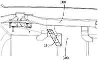
Referring to fig. 2 to 4, in some embodiments, the central bracket 210 includes a first end 212 connected to the beam 100 and a second end 213 connected to the vehicle body, and the first end 212 is provided with a supporting surface 211 for supporting the beam 100 along the first direction X and the second direction Y. In which the second end 213 of the center bracket 210 may be connected to the dash panel 300 of the vehicle body, and the distance between the beam body 100 and the dash panel 300 is short after the dash cross-member assembly is mounted on the vehicle, so that the center bracket 210 can be designed to be smaller in size. On the premise of ensuring the performance of the central support 210, a local hollow structure is adopted, so that further weight reduction is realized.
Referring to fig. 5, in some embodiments, the beam 100 is a tubular structure; since the performance requirement of the beam body 100 corresponding to the primary driving seat of the vehicle is higher than the performance requirement corresponding to the secondary driving seat of the vehicle, the thickness of the pipe wall 101 of the beam body 100 corresponding to the primary driving seat of the vehicle is greater than the thickness of the pipe wall 102 corresponding to the secondary driving seat of the vehicle. Thus, by optimizing the structural design of the beam body 100, a significant weight reduction can be achieved while ensuring performance.
In this embodiment, the beam body 100 may also be referred to as a tubular beam.
In some embodiments, the beam body 100 is made of carbon fiber material through a layup process, wherein a layup thickness of the carbon fiber material of the beam body 100 corresponding to a main operator's seat of the vehicle is greater than a layup thickness of a secondary operator's seat. With such an arrangement, the beam body 100 can be reduced in weight while the structural performance of the beam body 100 is ensured by the excellent specific stiffness and specific modulus of the carbon fiber material.
In this embodiment, the beam body 100 may be made of carbon fiber materials of different brands and manufacturers through a layering process, for example, T300 type carbon fiber with a unidirectional tape thickness of 0.2mm and/or T700 type carbon fiber with a unidirectional tape thickness of 0.15mm may be used, and compared with the T300 type carbon fiber, the T700 type carbon fiber has a higher mass fraction of carbon and a better tensile strength. By adopting a plurality of layers of carbon fiber composite materials with the same or different brands for compression molding and laying different quantities of carbon fiber composite materials or different thicknesses on the substrate, the beam body 100 with the beam wall thickness of 2 mm-2.5 mm can be formed, the thickness of the beam wall can be designed to be 2mm, 2.05mm, 2.35mm or 2.5mm, and the beam body 100 with the thicker beam wall can meet higher performance requirements. The cross-section of the beam body 100 may be rectangular, and the length and width dimensions of the cross-section may be 50mm by 50 mm. It is to be understood that the above dimensions are merely illustrative.
In this embodiment, performance may be analyzed and optimized through computer Aided engineering cae (computer Aided engineering), the number of the layers of the beam 100 corresponding to the main driving position with higher performance requirements is larger than that of the carbon fibers, in some embodiments, the layer design of the beam 100 corresponding to the main driving position may be 15 layers, the layer design corresponding to the auxiliary driving position may be 13 layers, the layer design of the beam 100 corresponding to the main driving position and the layer design of the beam 100 corresponding to the auxiliary driving position may be T300 type carbon fibers with a layer thickness of 0.2mm, and the layer design of the beam 100 corresponding to the area of the main driving position and the layer design of the beam corresponding to the auxiliary driving position may be T700 type carbon fibers with a layer thickness of 0.15mm, so that the beam wall thickness of the beam 100 corresponding to the main driving position is 2.35mm, and the beam wall thickness of the beam corresponding to the auxiliary driving position is 2.05 mm. Thus, by optimizing the carbon fiber laying layer design of the beam body 100, the weight can be greatly reduced on the premise of ensuring the performance.
In some embodiments, at least one of the steering column mounting bracket 231, the side bracket 220 and the central bracket 210 is integrally formed of a metal material. The steering column mounting bracket 231 mainly plays a role of mounting a steering column, and the side bracket 220 and the central bracket 210 mainly play a role of supporting the beam body 100, so that the performance requirements on the steering column mounting bracket 231, the side bracket 220 and the central bracket 210 are high, and in order to meet the performance requirements of the steering column mounting bracket 231, the side bracket 220 and the central bracket 210, and to achieve the weight reduction as much as possible, the magnesium alloy is preferably integrally formed, and the forming mode may be integral die-casting. Compared with steel and aluminum alloy, the magnesium alloy has lower density, so that the light weight can be better realized by adopting the magnesium alloy material while the structural performances of the steering column mounting bracket 231, the side bracket 220 and the central bracket 210 are ensured.
In some embodiments, the instrument panel cross-member assembly further includes an attachment bracket mounted to the beam 100 for mounting an external vehicle body structure, and the attachment bracket may be formed by injection molding of plastic, preferably a relatively low density Polycarbonate (PC), for light weight.
It should be noted that, the number of the brackets in the above embodiments may be increased or decreased according to actual situations. Through carrying out lightweight design to roof beam body 100, steering column installing support 231, side support 220 and central authorities support 210, under the prerequisite of guaranteeing each spare part performance, can make the instrument board beam assembly that this application provided's weight control about 2.6 kg, realize extremely making the lightweight.
In some embodiments, at least one of the steering column mounting bracket 231, the side bracket 220, and the central bracket 210 may be connected to the beam body 100 by a variety of connection methods, including but not limited to: the beam 100 is glued, riveted or connected by fasteners, such as bolts.
Referring to fig. 6 to 7, in some embodiments, the side bracket 220 is provided with a mounting groove, and the end of the beam 100 is inserted into the mounting groove; the groove wall of the mounting groove clings to the outer surface of the beam body 100. The side bracket 220 is used to support the beam body 100 from the end of the beam body 100, and the wall thickness of the side bracket 220 is 2mm to 2.5mm, and may be 2mm, 2.3mm, or 2.5mm, for example. The side bracket 220 can be connected with the beam body 100 by gluing and riveting, and the wall of the mounting groove is provided with a gluing surface 201 and a riveting hole for connecting with the beam body 100. In this embodiment, the side bracket 220 may include a left side bracket 220 for supporting the girder 100 at the left side of the girder 100 and/or a right side bracket 220 for supporting the girder 100 at the right side of the girder 100.
Referring to fig. 8, in some embodiments, in order to further reduce the overall structural size of the instrument panel beam assembly, a portion of the beam body 100 corresponding to a main driving seat of the vehicle is bent in a first direction to form a bypass portion 110, and a steering column mounting bracket 231 is mounted to the bypass portion 110. The beam body 100 is bent in the first direction, that is, the front-rear direction of the vehicle, to form the avoiding portion 110, so that the steering column mounting bracket 231 is mounted behind the avoiding portion 110, and the space occupied by the steering column mounting bracket 231 in the circumferential direction of the beam body 100 can be saved, and further, the overall structural size of the instrument panel beam assembly can be reduced.
In this embodiment, in order to firmly mount the steering column mounting bracket 231, the avoiding portion 110 includes two curved portions curved along the first direction and a straight portion connected between the two curved portions, the straight portion facilitates the steering column mounting bracket 231 to be in contact with the beam 100 in a flat manner, so as to improve the connection stability of the steering column mounting bracket 231, and the two curved portions connected by the straight portion can effectively prevent the steering column mounting bracket 231 from sliding along the beam 100, thereby further improving the mounting stability of the steering column mounting bracket 231.
Referring to fig. 9 to 10, in the present embodiment, the steering column mounting bracket 231 is provided with an adhesive surface 201 connected to the beam 100, and the steering column mounting bracket 231 may be connected to the beam 100 by adhesive. In order to improve the connection stability of the steering column mounting bracket 231 and the beam body 100, the instrument panel cross beam assembly further includes a connecting cover 232 for fixing the steering column mounting bracket 231, and the steering column mounting bracket 231 and the connecting cover 232 can be fixed on the beam body 100 by fasteners such as bolts, etc., so as to further improve the connection stability of the steering column mounting bracket 231 and the beam body 100. The steering column mounting bracket 231 and/or the connecting cover 232 may be formed by die-casting a magnesium alloy material, and the wall thickness of the steering column mounting bracket 231 and/or the connecting cover 232 is 2mm to 2.5mm, for example, 2mm, 2.3mm, or 2.5 mm.
The following explains an assembling manner of the instrument panel cross member assembly provided in the present embodiment:
the side bracket 220 can be connected with the beam body 100 by gluing and riveting; the steering column mounting bracket 231 and the connecting cover 232 can be connected and fixed on the beam body 100 through fasteners such as bolts and the like, and are connected with the beam body 100 on the contact surface in an adhesive bonding mode; the central bracket 210 and other plastic brackets can be connected to the beam 100 by gluing. The above-described assembling manner can ensure the accuracy of the assembling position by the assembling jig.
Having described in detail embodiments of a fascia cross member assembly provided herein, the present application further provides a vehicle including a fascia cross member assembly as in any of the embodiments above.
The application provides a vehicle, which comprises an instrument panel beam assembly, wherein the instrument panel beam assembly comprises a beam body 100, a steering column mounting bracket 231 and at least one side bracket 220, the steering column mounting bracket 231 is mounted on the beam body 100, the beam body 100 is connected with two sides of a vehicle body through the at least one side bracket 220, and the steering column mounting bracket 231 is arranged corresponding to a main driving position of the vehicle; the vehicle body support structure further comprises a central support 210 mounted on the beam body 100, wherein the central support 210 is used for supporting the beam body 100 in a first direction and a second direction, the first direction is the front-back direction of the vehicle, and the second direction is the height direction of the vehicle. Through optimizing structural design, avoided among the correlation technique the design defect of the support that plays supporting role to roof beam body 100, make the size of installing in the central authorities support 210 of roof beam body 100 littleer, lightened the weight of central authorities support 210, and then can lighten the weight of instrument board crossbeam assembly to satisfy body construction's lightweight requirement.
The solution of the present application has been described in detail hereinabove with reference to the drawings. In the above embodiments, the descriptions of the respective embodiments have respective emphasis, and for parts that are not described in detail in a certain embodiment, reference may be made to related descriptions of other embodiments. Those skilled in the art should also appreciate that acts and modules referred to in the specification are not necessarily required for the application. In addition, it can be understood that the steps in the method of the embodiment of the present application may be sequentially adjusted, combined, and deleted according to actual needs, and the modules in the device of the embodiment of the present application may be combined, divided, and deleted according to actual needs.
Having described embodiments of the present application, the foregoing description is intended to be exemplary, not exhaustive, and not limited to the disclosed embodiments. Many modifications and variations will be apparent to those of ordinary skill in the art without departing from the scope and spirit of the described embodiments. The terminology used herein is chosen in order to best explain the principles of the embodiments, the practical application, or improvements made to the technology in the marketplace, or to enable others of ordinary skill in the art to understand the embodiments disclosed herein.
Claims (10)
1. An instrument panel beam assembly, comprising:
the steering column mounting bracket is arranged corresponding to a main driving position of a vehicle;
the vehicle body supporting structure comprises a beam body, and is characterized by further comprising a central support arranged on the beam body, wherein the central support is used for supporting the beam body in a first direction and a second direction, the first direction is the front-back direction of a vehicle, and the second direction is the height direction of the vehicle.
2. The instrument panel cross-member assembly of claim 1, wherein:
at least one of the steering column mounting bracket, the side bracket and the central bracket is glued to the beam body; or
At least one of the steering column mounting bracket, the side bracket and the central bracket is riveted to the beam body; or
At least one of the steering column mounting bracket, the side bracket and the center bracket is connected to the beam body by a fastener.
3. The instrument panel beam assembly of claim 2 wherein:
the beam body is of a tubular structure;
The thickness of the pipe wall of the beam body corresponding to a main driving position of the vehicle is larger than that of the pipe wall corresponding to a secondary driving position of the vehicle.
4. The instrument panel cross-member assembly of claim 3, wherein:
the beam body is made of carbon fiber materials through a layering process, wherein the layering thickness of the carbon fiber materials, corresponding to the main driving position of the vehicle, of the beam body is larger than the layering thickness of the carbon fiber materials, corresponding to the auxiliary driving position of the vehicle.
5. The instrument panel cross-member assembly of claim 1, wherein:
the central support comprises a first end and a second end, wherein the first end is connected with the beam body, the second end is connected with the vehicle body, and the first end is provided with a supporting surface which supports the beam body along the first direction and the second direction.
6. The instrument panel cross-member assembly of claim 1, wherein:
the side support is provided with an installation groove, and the end part of the beam body is inserted in the installation groove; the groove wall of the mounting groove is tightly attached to the outer surface of the end part of the beam body.
7. The instrument panel cross-member assembly of claim 1, wherein:
the beam body is bent towards the first direction corresponding to the position of a main driving position of the vehicle to form an avoiding part, and the steering column mounting support is mounted on the avoiding part.
8. The instrument panel beam assembly of claim 1 wherein:
at least one of the steering column mounting bracket, the side bracket and the central bracket is integrally formed of a metal material.
9. The instrument panel beam assembly of claim 3 wherein:
the cross-section of the beam body comprises a rectangle.
10. A vehicle comprising the instrument panel beam assembly of any one of claims 1-9.
Priority Applications (1)
| Application Number | Priority Date | Filing Date | Title |
|---|---|---|---|
| CN202220161383.0U CN216660055U (en) | 2022-01-20 | 2022-01-20 | Instrument board beam assembly and vehicle |
Applications Claiming Priority (1)
| Application Number | Priority Date | Filing Date | Title |
|---|---|---|---|
| CN202220161383.0U CN216660055U (en) | 2022-01-20 | 2022-01-20 | Instrument board beam assembly and vehicle |
Publications (1)
| Publication Number | Publication Date |
|---|---|
| CN216660055U true CN216660055U (en) | 2022-06-03 |
Family
ID=81763094
Family Applications (1)
| Application Number | Title | Priority Date | Filing Date |
|---|---|---|---|
| CN202220161383.0U Active CN216660055U (en) | 2022-01-20 | 2022-01-20 | Instrument board beam assembly and vehicle |
Country Status (1)
| Country | Link |
|---|---|
| CN (1) | CN216660055U (en) |
-
2022
- 2022-01-20 CN CN202220161383.0U patent/CN216660055U/en active Active
Similar Documents
| Publication | Publication Date | Title |
|---|---|---|
| US10086881B2 (en) | Front vehicle body structure | |
| US20020145307A1 (en) | Floor panel for an automobile | |
| JP2002362436A (en) | Rear vehicle body structure | |
| US20090058144A1 (en) | Chassis frame for fuel cell vehicle | |
| CN216660055U (en) | Instrument board beam assembly and vehicle | |
| CN212738286U (en) | Vehicle front cabin assembly and vehicle | |
| CN212889832U (en) | Left suspension system integrated with storage battery tray and vehicle | |
| CN101362450B (en) | Under-cover support structure | |
| CN210634640U (en) | Front wall upper cross beam structure and vehicle | |
| CN112208645A (en) | Front wall upper cross beam structure and vehicle | |
| CN217533011U (en) | Instrument panel frame and vehicle | |
| CN215474288U (en) | Automobile top cover and flying automobile with same | |
| CN117382745A (en) | Instrument panel beam and vehicle | |
| CN217864322U (en) | Steering column assembly and vehicle with same | |
| CN217396666U (en) | Instrument board stiffening beam assembly and vehicle of vehicle | |
| CN219969545U (en) | Vehicle trunk assembly and vehicle | |
| CN212473657U (en) | Vehicle body structure and vehicle | |
| CN219029562U (en) | Front wall assembly of vehicle and vehicle | |
| CN112896325B (en) | Vehicle front end frame and vehicle | |
| CN220315131U (en) | Instrument board crossbeam assembly, instrument board assembly and vehicle | |
| CN220577364U (en) | Cabin assembly and generalized frame | |
| CN219446697U (en) | Door reinforcement, door assembly and vehicle | |
| CN111806572B (en) | Platformized front surrounding plate structure | |
| CN220281504U (en) | Vehicle body framework and vehicle | |
| CN216034674U (en) | Vehicle front structure |
Legal Events
| Date | Code | Title | Description |
|---|---|---|---|
| GR01 | Patent grant | ||
| GR01 | Patent grant |