CN216650157U - High-efficient heat dissipation case of installation thing networking device - Google Patents
High-efficient heat dissipation case of installation thing networking device Download PDFInfo
- Publication number
- CN216650157U CN216650157U CN202121983848.2U CN202121983848U CN216650157U CN 216650157 U CN216650157 U CN 216650157U CN 202121983848 U CN202121983848 U CN 202121983848U CN 216650157 U CN216650157 U CN 216650157U
- Authority
- CN
- China
- Prior art keywords
- air
- internet
- heat dissipation
- fixedly connected
- things
- Prior art date
- Legal status (The legal status is an assumption and is not a legal conclusion. Google has not performed a legal analysis and makes no representation as to the accuracy of the status listed.)
- Active
Links
Images

Classifications
-
- Y—GENERAL TAGGING OF NEW TECHNOLOGICAL DEVELOPMENTS; GENERAL TAGGING OF CROSS-SECTIONAL TECHNOLOGIES SPANNING OVER SEVERAL SECTIONS OF THE IPC; TECHNICAL SUBJECTS COVERED BY FORMER USPC CROSS-REFERENCE ART COLLECTIONS [XRACs] AND DIGESTS
- Y02—TECHNOLOGIES OR APPLICATIONS FOR MITIGATION OR ADAPTATION AGAINST CLIMATE CHANGE
- Y02D—CLIMATE CHANGE MITIGATION TECHNOLOGIES IN INFORMATION AND COMMUNICATION TECHNOLOGIES [ICT], I.E. INFORMATION AND COMMUNICATION TECHNOLOGIES AIMING AT THE REDUCTION OF THEIR OWN ENERGY USE
- Y02D10/00—Energy efficient computing, e.g. low power processors, power management or thermal management
Landscapes
- Cooling Or The Like Of Electrical Apparatus (AREA)
Abstract
The utility model provides a high-efficiency heat dissipation box for installing an internet of things device, and relates to the technical field of related internet of things, the high-efficiency heat dissipation box comprises a device shell, wherein two sides above the device shell are fixedly connected with baffle plates, two sides at the bottom end of the device shell are fixedly connected with bases, a fixing frame is fixedly installed at the bottom in the device shell, an internet of things host is arranged above the fixing frame, a top cover is movably connected above the internet of things host, an air pump is fixedly installed above the left side of a transverse plate, the right side of the air pump is fixedly connected with an air suction pipe, the left side of the air pump is provided with an air outlet positioned below the baffle plates, the hot air generated by the main machine of the internet of things is sucked and exhausted through an air guide port arranged at the lower part of the left side of the transverse plate, the air of the internet of things host can flow in a single direction at intervals of the partition plates, so that the heat dissipation capability of the internet of things host is stronger.
Description
Technical Field
The utility model relates to the technical field of internet of things chassis correlation, in particular to a high-efficiency heat dissipation box for installing an internet of things device.
Background
The internet of things is an important component of a new generation of information technology and is also an important development stage of an 'informatization' era, when the internet of things is continuously developed, a series of electronic elements such as cables, sensors and controllers in a case of the internet of things are more and more concentrated in the case, and the working efficiency of the case is reduced due to long-time work. Including relevant integrated component such as sensor, controller in the thing networking, these integrated component can be adorned in the install bin, in the course of the work, can produce a lot of heats, in case the radiating effect is poor, will influence the work efficiency of whole equipment, for this reason, provides an installation thing networking device's high-efficient heat dissipation case.
SUMMERY OF THE UTILITY MODEL
The utility model aims to solve the problems in the background technology, and provides a high-efficiency heat dissipation box for installing an internet of things device.
In order to achieve the purpose, the utility model adopts the following technical scheme:
the utility model provides an installation thing networking device's high-efficient heat dissipation case, includes the device shell, device shell top both sides fixedly connected with baffle, bottom fixed mounting has the mount in the device shell, the mount top is provided with the thing networking host computer, and the air pump is installed to device shell inner wall top, the breathing pipe is installed in the air pump outside, the gas vent that is located the baffle below is seted up in the air pump left side.
Preferably, the bottom of the air suction pipe is fixedly connected with an air guide port located below the left side of the transverse plate, and an air inlet is formed below the right side of the transverse plate.
Preferably, the air inlet top fixedly connected with intake pipe, the intake pipe is the U-shaped setting, and sets up the induction port that is located the baffle below intake pipe right side below.
Preferably, all be provided with the filter screen on induction port and the gas vent, seted up the draw-in groove in the intake pipe that is located induction port top, and swing joint has the air screen in the draw-in groove.
Preferably, the fixing frame is provided with ventilation holes at two sides, and a partition plate is fixedly connected above the side wall of the right side of the fixing frame.
Preferably, the top end of the partition board is fixedly connected to the bottom of the transverse board, and the air inlet is located on the right side of the partition board.
Preferably, diaphragm middle part threaded connection has the threaded rod, the threaded rod bottom is rotated and is connected in the pivot top, and top cap bottom fixedly connected with rubber cushion.
Preferably, the gaskets are fixedly mounted on two sides of the bottom of the fixing frame, and the top ends of the gaskets are attached to the bottom of the Internet of things host.
Preferably, the two sides of the bottom end of the device shell are fixedly connected with a base.
Preferably, thing networking host computer top swing joint has the top cap, the top cap top is rotated and is connected with the pivot, the pivot top is provided with the diaphragm, diaphragm both sides fixed connection is on the device shell inside wall.
The utility model provides a high-efficiency heat dissipation box for installing an internet of things device, which has the following beneficial effects:
this kind of high-efficient heat dissipation case of installation thing networking device sets up the below at the baffle through gas vent and induction port, the induction port is provided with the filter screen with the gas vent, the draw-in groove has been seted up in the induction port top intake pipe, air filter plate swing joint is in the draw-in groove, make its air intake back filter the air through air filter plate cooperation filter screen, prevent that the dust from entering, the fixed baffle that is provided with in air inlet left side, the air inlet transmits air to the diaphragm below, the ventilation hole transmission of seting up on through the mount lateral wall dispels the heat in to the thing networking host computer, the steam that the thing networking host computer produced leads the air port suction discharge of seting up through diaphragm left side below, through the baffle interval, make its air carry out one-way flow, it is stronger to make its thing networking host computer heat-sinking capability in.
This kind of high-efficient heat dissipation case of installation thing networking device rotates through the top cap top and is connected with the pivot, and the pivot top rotates and is connected with the threaded rod, and threaded rod threaded connection is on the diaphragm, and the thing networking host computer is inlayed in the mount, upwards rises the top cap through rotating the threaded rod, opens the mount, makes its thing networking host computer later maintenance dismouting more convenient.
Drawings
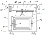
FIG. 1 is a schematic cross-sectional view of the front structure of the present invention;
FIG. 2 is a schematic view of the structure of the intake pipe of the present invention;
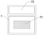
FIG. 3 is a schematic side view of the fixing frame of the present invention;
illustration of the drawings:
the device comprises a device shell-1, a baffle-2, an air pump-3, an air suction pipe-31, an air outlet-32, a top cover-4, a rotating shaft-41, a transverse plate-5, a threaded rod-51, an air inlet pipe-6, an air suction port-61, an air filter plate-62, a fixed frame-7, an air vent-71, a partition plate-72, a base-8, an Internet of things host-9 and a gasket-91.
Detailed Description
The technical solutions in the embodiments of the present invention will be clearly and completely described below with reference to the drawings in the embodiments of the present invention, and it is obvious that the described embodiments are only a part of the embodiments of the present invention, and not all of the embodiments. All other embodiments, which can be derived by a person skilled in the art from the embodiments given herein without making any creative effort, shall fall within the protection scope of the present invention.
Referring to fig. 1-3, a high-efficiency heat dissipation box for installing an internet of things device comprises a device shell 1, wherein two sides of the upper part of the device shell 1 are fixedly connected with baffle plates 2, two sides of the bottom end of the device shell 1 are fixedly connected with a base 8, a fixed frame 7 is fixedly installed at the bottom part in the device shell 1, an internet of things host machine 9 is arranged above the fixed frame 7, a top cover 4 is movably connected above the internet of things host machine 9, a rotating shaft 41 is rotatably connected above the top cover 4, a transverse plate 5 is arranged above the rotating shaft 41, two sides of the transverse plate 5 are fixedly connected on the inner side wall of the device shell 1, an air pump 3 is fixedly installed above the left side of the transverse plate 5, the right side of the air pump 3 is fixedly connected with an air suction pipe 31, an air outlet 32 positioned below the baffle plates 2 is arranged at the left side of the air pump 3, an air guide port positioned below the transverse plate 5 is fixedly connected at the bottom part of the air suction pipe 31, hot air is sucked and transmitted into the air suction pipe 31 to be discharged, an air inlet is arranged below the right side of the transverse plate 5, air is transmitted into a fixing frame 8 below through the air inlet, an air inlet pipe 6 is fixedly connected above the air inlet, the air is transmitted to the air inlet through the air inlet pipe 6 to be discharged, the air inlet pipe 6 is arranged in a U shape to facilitate the circulation of the air, an air suction port 61 positioned below the baffle plate 2 is arranged below the right side of the air inlet pipe 6, the air is sucked through the air suction port 61, filter screens are arranged on the air suction port 61 and an air exhaust port 32 respectively to block dust in the air through the filter screens, a clamping groove is arranged in the air inlet pipe 6 above the air suction port 61, a filter plate 62 is movably connected in the clamping groove, the filter plate 62 filters the sucked air to prevent the dust from being transmitted into the device, vent holes 71 are arranged on two sides of the fixing frame 7 to circulate the air through the vent holes 71, and a partition plate 72 is fixedly connected above the right side wall of the fixing frame 7, the hot air generated by the Internet of things host machine 9 is separated from the sucked air through the partition plate 72, the top end of the partition plate 72 is fixedly connected to the bottom of the transverse plate 5, the air inlet is positioned on the right side of the partition plate 72, the sucked air is discharged into the lower part through the air inlet, the partition plate 72 separates the air, the threaded rod 51 is in threaded connection with the middle part of the transverse plate 5, the top cover 4 is driven to ascend and descend through the ascending and descending of the rotating threaded rod 51, the bottom end of the threaded rod 51 is rotatably connected above the rotating shaft 41, the top cover 4 is pulled to be opened through the rotating shaft 41 when the threaded rod 51 rotates to ascend, the rubber cushion layer is fixedly connected to the bottom of the top cover 4, the Internet of things host machine 9 is covered below by the top cover 4 through the bottom rubber cushion layer for protection, gaskets 91 are fixedly installed on two sides of the bottom of the fixing frame 7, the bottom of the Internet of things host machine 9 is supported through the gaskets 91, so that the Internet of things host machine 9 has certain pressure resistance, and the top end of the gaskets 91 is attached to the bottom of the Internet of things host machine 9, the installation of the host 9 of the internet of things is more stable.
The working principle is as follows: the bottom of a device shell 1 is fixedly connected with a base 8 support, two sides above the device shell 1 are fixedly connected with a baffle 2 to protect an air outlet 32 and an air inlet 61, an internet of things host 9 is fixedly installed in a fixed frame 7, the bottom is supported by a gasket 91 to be more stable, when air is sucked in by the air inlet 61, dust in the air is simply filtered by a filter screen arranged on the outer side and then is transmitted into an air inlet pipe 6, the air is filtered by an air filter plate 62 movably connected in the air inlet pipe 6 and then is transmitted into the air inlet to be discharged, the air filter plate 62 is periodically taken out from a clamping groove of the air inlet pipe 6 to be replaced and cleaned, the air filter plate 62 is prevented from being blocked to influence air inlet, after the air is discharged by the air inlet, the air is separated by a partition plate 72 fixedly connected below a transverse plate 5 on the left side, and the air is transmitted into the fixed frame 7 through a ventilation hole 71 formed in the right side of the fixed frame 7 to dissipate heat, the steam that thing networking host computer 9 produced passes through ventilation hole 71 discharge that the mount 7 left side was seted up, steam is through top air guide port suction transmission to breathing pipe 31 in, breathing pipe 31 inhales steam and transmits to air pump 3 in, discharge steam from gas vent 32 through air pump 3, rotate diaphragm 5 middle part threaded rod 51, threaded rod 51 pulling bottom rotates the pivot 41 of connecting and rises, through the pivot 41 pulling top cap 4 rise open mount 7, open closed mount 7 through rotating threaded rod 51 pulling below top cap 4, it is more convenient to make its thing networking host computer 9 later maintenance dismouting.
The above description is only for the preferred embodiment of the present invention, but the scope of the present invention is not limited thereto, and any person skilled in the art should be considered to be within the technical scope of the present invention, and equivalent alternatives or modifications according to the technical solution of the present invention and the inventive concept thereof should be covered by the scope of the present invention.
Claims (10)
1. The utility model provides an installation thing networking device's high-efficient heat dissipation case, includes device shell (1), device shell (1) top both sides fixedly connected with baffle (2), bottom fixed mounting has mount (7) in device shell (1), mount (7) top is provided with thing networking host computer (9), its characterized in that: air pump (3) is installed to device shell (1) inner wall top, breathing pipe (31) are installed in the air pump (3) outside, gas vent (32) that are located baffle (2) below are seted up on air pump (3) left side.
2. The efficient heat dissipation box for installing the internet of things device according to claim 1, wherein an air guide port located below the left side of the transverse plate (5) is fixedly connected to the bottom of the air suction pipe (31), and an air inlet is formed below the right side of the transverse plate (5).
3. The efficient heat dissipation box for installing the internet of things device according to claim 2, wherein an air inlet pipe (6) is fixedly connected above the air inlet, the air inlet pipe (6) is arranged in a U shape, and an air suction port (61) located below the baffle (2) is formed in the lower portion of the right side of the air inlet pipe (6).
4. The high-efficiency heat dissipation box for installing the IOT device, according to claim 3, wherein the air inlet (61) and the air outlet (32) are provided with filter screens, a clamping groove is formed in the air inlet pipe (6) above the air inlet (61), and an air filter plate (62) is movably connected in the clamping groove.
5. The efficient heat dissipation box for installing the internet of things device as claimed in claim 2, wherein ventilation holes (71) are formed in two sides of the fixing frame (7), and a partition plate (72) is fixedly connected to the upper portion of the right side wall of the fixing frame (7).
6. The high-efficiency heat dissipation box for installing the internet of things device as claimed in claim 5, wherein the top end of the partition plate (72) is fixedly connected to the bottom of the transverse plate (5), and the air inlet is located on the right side of the partition plate (72).
7. The efficient heat dissipation box for installing the internet of things device as claimed in claim 2, wherein a threaded rod (51) is connected to the middle of the transverse plate (5) in a threaded manner, the bottom end of the threaded rod (51) is rotatably connected above the rotating shaft (41), and a rubber cushion layer is fixedly connected to the bottom of the top cover (4).
8. The efficient heat dissipation box for installing the IOT device, according to claim 1, is characterized in that gaskets (91) are fixedly installed on two sides of the bottom of the fixing frame (7), and the top ends of the gaskets (91) are attached to the bottom of the IOT host (9).
9. The efficient heat dissipation box for installing the internet of things device is characterized in that bases (8) are fixedly connected to two sides of the bottom end of the device shell (1).
10. The efficient heat dissipation box for installing the internet of things device according to claim 1, wherein a top cover (4) is movably connected above the internet of things host (9), a rotating shaft (41) is rotatably connected above the top cover (4), a transverse plate (5) is arranged above the rotating shaft (41), and two sides of the transverse plate (5) are fixedly connected to the inner side wall of the device shell (1).
Priority Applications (1)
| Application Number | Priority Date | Filing Date | Title |
|---|---|---|---|
| CN202121983848.2U CN216650157U (en) | 2021-08-23 | 2021-08-23 | High-efficient heat dissipation case of installation thing networking device |
Applications Claiming Priority (1)
| Application Number | Priority Date | Filing Date | Title |
|---|---|---|---|
| CN202121983848.2U CN216650157U (en) | 2021-08-23 | 2021-08-23 | High-efficient heat dissipation case of installation thing networking device |
Publications (1)
| Publication Number | Publication Date |
|---|---|
| CN216650157U true CN216650157U (en) | 2022-05-31 |
Family
ID=81722784
Family Applications (1)
| Application Number | Title | Priority Date | Filing Date |
|---|---|---|---|
| CN202121983848.2U Active CN216650157U (en) | 2021-08-23 | 2021-08-23 | High-efficient heat dissipation case of installation thing networking device |
Country Status (1)
| Country | Link |
|---|---|
| CN (1) | CN216650157U (en) |
Cited By (1)
| Publication number | Priority date | Publication date | Assignee | Title |
|---|---|---|---|---|
| WO2023088504A3 (en) * | 2022-08-04 | 2023-09-21 | 安徽海瑞通科技股份有限公司 | Dustproof network cabinet |
-
2021
- 2021-08-23 CN CN202121983848.2U patent/CN216650157U/en active Active
Cited By (1)
| Publication number | Priority date | Publication date | Assignee | Title |
|---|---|---|---|---|
| WO2023088504A3 (en) * | 2022-08-04 | 2023-09-21 | 安徽海瑞通科技股份有限公司 | Dustproof network cabinet |
Similar Documents
| Publication | Publication Date | Title |
|---|---|---|
| CN216650157U (en) | High-efficient heat dissipation case of installation thing networking device | |
| CN207731225U (en) | Case radiation auxiliary device | |
| CN201590752U (en) | High-efficient heat dissipation device for frequency conversion control cabinet | |
| CN106765709A (en) | The permanent net perseverance oxygen combination wind cabinet of constant temperature and humidity | |
| CN218772789U (en) | Electrical apparatus box heat radiation structure and heat pump set | |
| CN208139506U (en) | Communications equipment room ventilation device | |
| CN201876783U (en) | Heat-dissipation and dustproof computer case | |
| CN213755486U (en) | Network load balancing device based on big data analysis | |
| CN212429246U (en) | High-efficient environmental protection turbo blower | |
| CN209068587U (en) | Smoke evacuation system | |
| CN209982819U (en) | Heat dissipation type printed wiring board | |
| CN206117250U (en) | Direct current of being applied to high -altitude area cabinet that charges | |
| CN219779579U (en) | Dustproof power distribution cabinet | |
| CN214852549U (en) | Explosion-proof sewage purification equipment control box capable of conducting diversion and heat dissipation | |
| CN216218366U (en) | Dust removal and heat dissipation cabinet for high-voltage frequency converter of power distribution room in steel production | |
| CN211880816U (en) | Frequency converter shell with dustproof structure | |
| CN210769394U (en) | Exhaust device before environmental protection application | |
| CN215576468U (en) | Dustproof effectual computer mainframe dispels heat | |
| CN215887538U (en) | Preheating device of rapid steamer | |
| CN219062095U (en) | Sealing structure for indoor FFU fan installation | |
| CN220758694U (en) | RO dense water recovery unit | |
| CN211781324U (en) | Integrated kitchen bellows | |
| CN213070427U (en) | High-efficient radiating electronic display station board | |
| CN214275975U (en) | Window type air conditioner | |
| CN220042763U (en) | Virtual studio power control box |
Legal Events
| Date | Code | Title | Description |
|---|---|---|---|
| GR01 | Patent grant | ||
| GR01 | Patent grant | ||
| TR01 | Transfer of patent right |
Effective date of registration: 20221018 Address after: Floor 3, Financial Holding Building, Binhe New District, Shenmu, Yulin, Shaanxi 719300 Patentee after: Shaanxi Carbon Cube Digital Technology Co.,Ltd. Address before: 266000 Qingdao Binhai college, 425 Jialing Jiangxi Road, Huangdao District, Qingdao, Shandong Patentee before: Xiong Jincheng |
|
| TR01 | Transfer of patent right |