CN216647774U - Intelligent multimedia liquid crystal display for office meeting - Google Patents
Intelligent multimedia liquid crystal display for office meeting Download PDFInfo
- Publication number
- CN216647774U CN216647774U CN202220043180.1U CN202220043180U CN216647774U CN 216647774 U CN216647774 U CN 216647774U CN 202220043180 U CN202220043180 U CN 202220043180U CN 216647774 U CN216647774 U CN 216647774U
- Authority
- CN
- China
- Prior art keywords
- frame
- shaft
- supporting
- control
- adjusting
- Prior art date
- Legal status (The legal status is an assumption and is not a legal conclusion. Google has not performed a legal analysis and makes no representation as to the accuracy of the status listed.)
- Active
Links
- 239000004973 liquid crystal related substance Substances 0.000 title claims abstract description 11
- 230000005540 biological transmission Effects 0.000 claims description 8
- 238000012986 modification Methods 0.000 description 2
- 230000004048 modification Effects 0.000 description 2
- 230000009286 beneficial effect Effects 0.000 description 1
- 238000010586 diagram Methods 0.000 description 1
- 230000000694 effects Effects 0.000 description 1
- 238000000034 method Methods 0.000 description 1
- 230000001105 regulatory effect Effects 0.000 description 1
- 230000000452 restraining effect Effects 0.000 description 1
- 239000007858 starting material Substances 0.000 description 1
Images



Landscapes
- Devices For Indicating Variable Information By Combining Individual Elements (AREA)
Abstract
The utility model discloses an intelligent multimedia liquid crystal display for an office meeting, which comprises a supporting base, wherein an adjusting mechanism is arranged at the upper end of the supporting base, the adjusting mechanism comprises a fixed block fixedly arranged at the upper end of the supporting base, a supporting frame is fixedly arranged at the upper end of the fixed block, a threaded shaft is movably arranged at the inner side of the supporting frame, a moving frame is arranged at one side of the outer side of the threaded shaft, which is close to the supporting frame, in a threaded manner, a limiting rod is movably arranged in the moving frame, a control frame is fixedly arranged at the upper end of the moving frame, and a supporting rod is movably arranged at the inner side of the control frame. According to the intelligent multimedia liquid crystal display for the office meeting, the motor is started to enable the threaded shaft to rotate, so that the threaded shaft drives the movable frame to move along the limiting rod, and the supporting rod pulls the adjusting frame to move downwards, and the purpose of conveniently accommodating the display screen is achieved.
Description
Technical Field
The utility model relates to the technical field of office meeting equipment, in particular to an intelligent multimedia liquid crystal display for an office meeting.
Background
The office meeting is an important administrative means and plays an important role in the aspects of communicating information, discussing problems, summarizing and exchanging, arranging tasks, coordinating and unifying, making decisions and the like, and the office meeting is a working mode that relevant responsible persons of one department take conference discussion and process affairs; traditional intelligence is multi-media LCD for office meeting has some shortcomings, because traditional intelligence is multi-media LCD for office meeting be the snap-on the support frame to make after office meeting has been driven, be not convenient for accomodate, and because the support frame is highly higher with multi-media LCD for intelligent office meeting supports, and the height of meeting room door is limited, thereby the intelligence of being not convenient for multi-media LCD for office meeting removes out of the meeting room.
SUMMERY OF THE UTILITY MODEL
The utility model mainly aims to provide an intelligent multimedia liquid crystal display for an office meeting, which can effectively solve the problems in the background technology.
In order to achieve the purpose, the utility model adopts the technical scheme that:
an intelligent multimedia liquid crystal display for office meetings comprises a supporting base, wherein the upper end of the supporting base is provided with an adjusting mechanism, the adjusting mechanism comprises a fixed block fixedly arranged at the upper end of the supporting base, a supporting frame is fixedly arranged at the upper end of the fixed block, a threaded shaft is movably arranged on the inner side of the supporting frame, a movable frame is arranged on one side of the outer side of the threaded shaft close to the supporting frame in a threaded manner, the inside of the moving frame is movably provided with a limiting rod, the upper end of the moving frame is fixedly provided with a control frame, a support rod is movably arranged at the inner side of the control frame, a control shaft is movably arranged in the support rod, the utility model discloses a bracing piece, including bracing piece, control frame, regulating spindle, threaded shaft, gear, support frame, bracing piece, and the opposite side of bracing piece is provided with the gear fixedly.
Preferably, the rear end meshing of a gear is provided with No. two gears, the inboard fixed transmission shaft that is provided with of No. two gears, the fixed mount pad that is provided with in one side that the upper end of supporting the base is close to the fixed block, the fixed motor that is provided with in upper end of mount pad.
Preferably, the rear end of transmission shaft is installed at the front end of motor department, the one end of restriction pole and the one end fixed connection of support frame, the control shaft extends to the inside of control frame, swing joint between control shaft and the control frame.
Preferably, the adjusting shaft extends into the adjusting frame, the adjusting shaft is movably connected with the adjusting frame, the control frame and the adjusting frame are both U-shaped, and the axial leads of the control shaft and the adjusting shaft are positioned on the same straight line.
Preferably, the lower extreme of supporting the base is fixed and is provided with the universal wheel, the upper end of alignment jig is fixed and is provided with the control panel, the upper end of control panel is fixed and is provided with the display screen.
Preferably, the number of the universal wheels is four, the four universal wheels are all distributed at four corners of the lower end of the supporting base, and the display screen is rectangular.
Compared with the prior art, the utility model has the following beneficial effects:
1. the universal wheels roll on the ground by pushing the display screen, so that the purpose of moving the display screen to a meeting room can be achieved.
2. Thereby make the screw shaft rotatory make the screw shaft drive the removal frame remove along the restriction pole and make bracing piece pulling alignment jig remove down through starter motor, can reach the purpose of being convenient for accomodate the display screen.
Drawings
FIG. 1 is a schematic diagram of an overall structure of an intelligent multimedia LCD for office meeting according to the present invention;
FIG. 2 is a schematic view of an adjusting mechanism of a multimedia liquid crystal display for intelligent office meeting according to the present invention;
FIG. 3 is a schematic view of a partially cut-away structure of an adjusting mechanism of a multimedia LCD for intelligent office meeting according to the present invention;
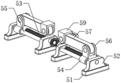
fig. 4 is a schematic view of an enlarged structure of a part a of an intelligent multimedia lcd for office meetings according to the present invention.
In the figure: 1. a support base; 2. a universal wheel; 3. a control panel; 4. a display screen; 5. an adjustment mechanism; 51. a fixed block; 52. a support frame; 53. a threaded shaft; 54. a movable frame; 55. a restraining bar; 56. a control frame; 57. a support bar; 58. a control shaft; 59. an adjusting bracket; 510. an adjustment shaft; 511. a first gear; 512. a second gear; 513. a drive shaft; 514. a motor; 515. and (7) mounting a seat.
Detailed Description
In order to make the technical means, the creation characteristics, the achievement purposes and the effects of the utility model easy to understand, the utility model is further described with the specific embodiments.
As shown in fig. 1-4, a multimedia liquid crystal display for intelligent office meeting comprises a supporting base 1, an adjusting mechanism 5 is arranged at the upper end of the supporting base 1, the adjusting mechanism 5 comprises a fixed block 51 fixedly arranged at the upper end of the supporting base 1, a supporting frame 52 is fixedly arranged at the upper end of the fixed block 51, a threaded shaft 53 is movably arranged at the inner side of the supporting frame 52, a moving frame 54 is arranged at one side of the outer side of the threaded shaft 53 close to the supporting frame 52 in a threaded manner, a limiting rod 55 is movably arranged inside the moving frame 54, a control frame 56 is fixedly arranged at the upper end of the moving frame 54, a supporting rod 57 is movably arranged inside the control frame 56, a control shaft 58 is movably arranged inside the supporting rod 57, an adjusting frame 59 is movably arranged at one side of the outer side of the supporting rod 57 close to the control frame 56, an adjusting shaft 510 is movably arranged at one side of the inner side of the supporting rod 57 close to the control shaft 58, the first gear 511 is fixedly arranged on the other side of the outer side of the threaded shaft 53 close to the support frame 52.
In this embodiment, a second gear 512 is engaged with the rear end of the first gear 511, a transmission shaft 513 is fixedly disposed inside the second gear 512, a mounting seat 515 is fixedly disposed on one side of the upper end of the support base 1 close to the fixing block 51, a motor 514 is fixedly disposed on the upper end of the mounting seat 515, the rear end of the transmission shaft 513 is mounted at the front end of the motor 514, one end of the limiting rod 55 is fixedly connected with one end of the support frame 52, the control shaft 58 extends into the control frame 56, the control shaft 58 is movably connected with the control frame 56, the adjusting shaft 510 extends into the adjusting frame 59, the adjusting shaft 510 is movably connected with the adjusting frame 59, the control frame 56 and the adjusting frame 59 are both U-shaped, and the axial leads of the control shaft 58 and the adjusting shaft 510 are located on the same straight line.
Specifically, the motor 514 is first started, so that the motor 514 drives the second gear 512 to rotate through the transmission shaft 513, because the second gear 512 is meshed with the first gear 511, the second gear 512 drives the first gear 511 to rotate, so that the first gear 511 drives the threaded shaft 53 to rotate, because the threaded shaft 53 is in threaded connection with the movable frame 54, the rotation of the threaded shaft 53 moves the movable frame 54 along the limiting rod 55, so that the movable frame 54 drives the control frame 56 to move, and the control frame 56 drives the supporting rod 57 to move through the control shaft 58, so that the supporting rod 57 pushes the adjusting frame 59 to move upwards through the adjusting shaft 510, so that the adjusting frame 59 drives the display screen 4 to move through the control plate 3, and the display screen 4 is moved to a specified position, after use, the motor 514 is first started to rotate reversely, so that the threaded shaft 53 rotates reversely, and the moving frame 54 moves reversely along the limiting rod 55, so that the control frame 56 pulls the supporting rod 57 to move reversely, and the supporting rod 57 pulls the adjusting frame 59 to move downwards, the threaded shaft 53 rotates by starting the motor 514, so that the threaded shaft 53 drives the moving frame 54 to move along the limiting rod 55, and the supporting rod 57 pulls the adjusting frame 59 to move downwards, and the purpose of conveniently accommodating the display screen 4 can be achieved.
In this embodiment, the fixed universal wheel 2 that is provided with of lower extreme of supporting base 1, the fixed control panel 3 that is provided with in upper end of alignment jig 59, the fixed display screen 4 that is provided with in upper end of control panel 3, the quantity of universal wheel 2 has four groups, four groups of universal wheels 2 all distribute in four corners of the lower extreme of supporting base 1, the shape of display screen 4 is the rectangle.
Specifically, the universal wheels 2 roll on the ground by pushing the display screen 4, so that the purpose of moving the display screen 4 to a meeting room can be achieved.
The working principle is as follows:
when in use, firstly, the motor (model: Y2-90L-2)514 is started, so that the motor 514 drives the second gear 512 to rotate through the transmission shaft 513, the second gear 512 drives the first gear 511 to rotate because the second gear 512 is meshed with the first gear 511, so that the first gear 511 drives the threaded shaft 53 to rotate, the movable frame 54 moves along the limiting rod 55 due to the threaded connection between the threaded shaft 53 and the movable frame 54, so that the movable frame 54 drives the control frame 56 to move, the control frame 56 drives the supporting rod 57 to move through the control shaft 58, so that the supporting rod 57 pushes the adjusting frame 59 to move upwards through the adjusting shaft 510, so that the adjusting frame 59 drives the display screen (model: MXS8476)4 to move through the control panel 3, and the display screen 4 moves to a designated position, when after the use, firstly the motor 514 is started to rotate reversely, so that the threaded shaft 53 rotates reversely, and the moving frame 54 moves reversely along the limiting rod 55, so that the control frame 56 pulls the supporting rod 57 to move reversely, and the supporting rod 57 pulls the adjusting frame 59 to move downwards, so that the display screen 4 moves to the original position, at this time, the display screen 4 is pushed, so that the universal wheels 2 roll on the ground, so that the display screen 4 moves to a meeting room, the threaded shaft 53 rotates by starting the motor 514, so that the threaded shaft 53 drives the moving frame 54 to move along the limiting rod 55, and the supporting rod 57 pulls the adjusting frame 59 to move downwards, the purpose of conveniently accommodating the display screen 4 can be achieved.
The foregoing shows and describes the general principles and broad features of the present invention and advantages thereof. It will be understood by those skilled in the art that the present invention is not limited to the embodiments described above, which are given by way of illustration of the principles of the present invention, but that various changes and modifications may be made without departing from the spirit and scope of the utility model, and such changes and modifications are within the scope of the utility model as claimed. The scope of the utility model is defined by the appended claims and equivalents thereof.
Claims (6)
1. The utility model provides an intelligence is multimedia LCD for office meeting, includes support base (1), its characterized in that: the upper end of the supporting base (1) is provided with an adjusting mechanism (5), the adjusting mechanism (5) comprises a fixed block (51) fixedly arranged at the upper end of the supporting base (1), the upper end of the fixed block (51) is fixedly provided with a supporting frame (52), the inner side of the supporting frame (52) is movably provided with a threaded shaft (53), one side of the outer side of the threaded shaft (53) close to the supporting frame (52) is provided with a movable frame (54), the inner part of the movable frame (54) is movably provided with a limiting rod (55), the upper end of the movable frame (54) is fixedly provided with a control frame (56), the inner side of the control frame (56) is movably provided with a supporting rod (57), the inner part of the supporting rod (57) is movably provided with a control shaft (58), one side of the outer side of the supporting rod (57) close to the control frame (56) is movably provided with an adjusting frame (59), an adjusting shaft (510) is movably arranged on one side, close to the control shaft (58), of the inner portion of the supporting rod (57), and a first gear (511) is fixedly arranged on the other side, close to the supporting frame (52), of the outer side of the threaded shaft (53).
2. The intelligent multimedia lcd for office meeting as claimed in claim 1, wherein: the rear end meshing of a gear (511) is provided with No. two gear (512), the inboard fixed transmission shaft (513) that is provided with of No. two gear (512), one side fixed mounting seat (515) that are close to fixed block (51) in the upper end of supporting base (1), the upper end fixed motor (514) that is provided with of mounting seat (515).
3. The intelligent multimedia liquid crystal display for office meeting according to claim 2, characterized in that: the rear end of the transmission shaft (513) is installed at the front end of the motor (514), one end of the limiting rod (55) is fixedly connected with one end of the supporting frame (52), the control shaft (58) extends into the control frame (56), and the control shaft (58) is movably connected with the control frame (56).
4. The intelligent multimedia liquid crystal display for office meeting according to claim 2, characterized in that: the adjusting shaft (510) extends to the inside of the adjusting frame (59), the adjusting shaft (510) is movably connected with the adjusting frame (59), the control frame (56) and the adjusting frame (59) are both U-shaped, and the axial lines of the control shaft (58) and the adjusting shaft (510) are positioned on the same straight line.
5. The intelligent multimedia lcd for office meeting as claimed in claim 1, wherein: the lower extreme of supporting base (1) is fixed and is provided with universal wheel (2), the upper end of alignment jig (59) is fixed and is provided with control board (3), the upper end of control board (3) is fixed and is provided with display screen (4).
6. The intelligent multimedia LCD for office meeting of claim 5, wherein: the quantity of universal wheel (2) has four groups, four groups universal wheel (2) all distribute in four corners of the lower extreme of supporting base (1), the shape of display screen (4) is the rectangle.
Priority Applications (1)
| Application Number | Priority Date | Filing Date | Title |
|---|---|---|---|
| CN202220043180.1U CN216647774U (en) | 2022-01-10 | 2022-01-10 | Intelligent multimedia liquid crystal display for office meeting |
Applications Claiming Priority (1)
| Application Number | Priority Date | Filing Date | Title |
|---|---|---|---|
| CN202220043180.1U CN216647774U (en) | 2022-01-10 | 2022-01-10 | Intelligent multimedia liquid crystal display for office meeting |
Publications (1)
| Publication Number | Publication Date |
|---|---|
| CN216647774U true CN216647774U (en) | 2022-05-31 |
Family
ID=81725702
Family Applications (1)
| Application Number | Title | Priority Date | Filing Date |
|---|---|---|---|
| CN202220043180.1U Active CN216647774U (en) | 2022-01-10 | 2022-01-10 | Intelligent multimedia liquid crystal display for office meeting |
Country Status (1)
| Country | Link |
|---|---|
| CN (1) | CN216647774U (en) |
-
2022
- 2022-01-10 CN CN202220043180.1U patent/CN216647774U/en active Active
Similar Documents
| Publication | Publication Date | Title |
|---|---|---|
| CN216647774U (en) | Intelligent multimedia liquid crystal display for office meeting | |
| CN220832503U (en) | Rotary mobile phone display cabinet | |
| CN210440916U (en) | Multimedia mobile teaching demonstration equipment | |
| CN201018586Y (en) | Rotary pedestal for flat TV set | |
| CN213487587U (en) | Interactive remote teaching platform | |
| CN218914377U (en) | Gun type camera support | |
| CN114141128A (en) | Data analysis display device for accounting | |
| CN221146026U (en) | Multimedia presentation equipment | |
| CN221504569U (en) | Campus training room management platform | |
| CN218457796U (en) | Wall-hanging multimedia presentation platform that can accomodate | |
| CN218119235U (en) | Computer display adjusting seat | |
| CN220647577U (en) | LED display screen convenient to multi-angle adjustment | |
| CN221221700U (en) | Pipe bracket convenient to adjust | |
| CN219994862U (en) | Electronic sand table | |
| CN222479952U (en) | Data processing display terminal of direct current contactor travel parameter detection equipment | |
| CN212617329U (en) | 5G remote operation camera equipment | |
| CN222397804U (en) | Building information model show stand | |
| CN217030547U (en) | Rotatable meeting machine | |
| CN111102448B (en) | Liquid crystal display screen capable of remotely adjusting pictures and colors | |
| CN214752408U (en) | Economic law teaching device | |
| CN221504507U (en) | Display screen rotating structure | |
| CN221300625U (en) | Large-size electronic billboard | |
| CN220082701U (en) | Lifting type network conference flat plate | |
| CN220109346U (en) | Podium with show board | |
| CN215643363U (en) | Interactive topography sand table convenient to adjust |
Legal Events
| Date | Code | Title | Description |
|---|---|---|---|
| GR01 | Patent grant | ||
| GR01 | Patent grant |